

Cabletron Systems 42T, MicroMMAC 24T MICROMMAC-, MicroMMAC 44T MICROMMAC-, MICROMMAC-22T, MICROMMAC-24T User Manual
...Page 1

MICROMMAC-22T/24T/42T/44T
STA CKABLE T OKEN RING
INTELLIGENT HUBS
USER’S GUIDE
Page 2

NOTICE
per
Cabletron Systems reserves the right to make changes in specifications and other
information contained in this document without prior notice. The reader should in all cases
consult Cabletron Systems to determine whether any such changes have been made.
The hardware, firmware, or software described in this manual is subject to change without
notice.
IN NO EVENT SHALL CABLETRON SYSTEMS BE LIABLE FOR ANY
INCIDENTAL, INDIRECT, SPECIAL, OR CONSEQUENTIAL DAMAGES
WHATSOEVER (INCLUDING BUT NOT LIMITED TO LOST PROFITS) ARISING
OUT OF OR RELATED TO THIS MANUAL OR THE INFORMATION CONTAINED
IN IT, EVEN IF CABLETRON SYSTEMS HAS BEEN ADVISED OF, KNOWN, OR
SHOULD HAVE KNOWN, THE POSSIBILITY OF SUCH DAMAGES.
© Copyright March 1996 by:
Cabletron Systems, Inc.
P.O. Box 5005, Rochester, NH 03866-5005
All Rights Reserved
Printed in the United States of America
Order Number: 9031320 March 1996
MicroMMAC-22T , 24T, 42T, 44T , BRIM, and TPIM are trademarks of Cabletron Systems,
Inc.
SPECTRUM, LANVIEW, and Remote LANVIEW are registered trademarks of Cabletron
Systems, Inc.
IBM is a registered trademark of International Business Machines Corporation.
DEC, VT200, and VT300 are trademarks of Digital Equipment Corporation.
CompuServe is a trademark of Compuserve, Inc.
Printed On
Recycled Pa
iii
Page 3

NOTICE
FCC NOTICE
This device complies with Part 15 of the FCC rules. Operation is subject to the following
two conditions: (1) this device may not cause harmful interference, and (2) this de vice must
accept any interference received, including interference that may cause undesired
operation.
NOTE: This equipment has been tested and found to comply with the limits for a Class A
digital device, pursuant to Part 15 of the FCC rules. These limits are designed to provide
reasonable protection against harmful interference when the equipment is operated in a
commercial environment. This equipment uses, generates, and can radiate radio frequency
energy and if not installed in accordance with the operator’s manual, may cause harmful
interference to radio communications. Operation of this equipment in a residential area is
likely to cause interference in which case the user will be required to correct the
interference at his own expense.
WARNING: Changes or modifications made to this device which are not expressly
approved by the party responsible for compliance could void the user’s authority to operate
the equipment.
DOC NOTICE
This digital apparatus does not exceed the Class A limits for radio noise emissions from
digital apparatus set out in the Radio Interference Regulations of the Canadian Department
of Communications.
Le présent appareil numérique n’émet pas de bruits radioélectriques dépassant les limites
applicables aux appareils numériques de la class A prescrites dans le Règlement sur le
brouillage radioélectrique édicté par le ministère des Communications du Canada.
VCCI NOTICE
This equipment is in the 1st Class Category (information equipment to be used in
commercial and/or industrial areas) and conforms to the standards set by the Voluntary
Control Council for Interference by Information Technology Equipment (VCCI) aimed at
preventing radio interference in commercial and/or industrial areas.
Consequently, when used in a residential area or in an adjacent area thereto, radio
interference may be caused to radios and TV receivers, etc.
NEED JAP ANESE GRAPHIC TEXT HERE
BEFORE RELEASE
Read the instructions for correct handling.
iv
Page 4

NOTICE
CABLETRON SYSTEMS, INC. PROGRAM
LICENSE AGREEMENT
IMPORTANT: Before utilizing this product, carefully read this License Agreement.
This document is an agreement between you, the end user, and Cabletron Systems, Inc.
(“Cabletron”) that sets forth your rights and obligations with respect to the Cabletron
software program (the “Program”) contained in this package. The Program may be
contained in firmware, chips or other media. BY UTILIZING THE ENCLOSED
PRODUCT, YOU ARE AGREEING TO BECOME BOUND BY THE TERMS OF THIS
AGREEMENT, WHICH INCLUDES THE LICENSE AND THE LIMITATION OF
WARRANTY AND DISCLAIMER OF LIABILITY. IF YOU DO NOT AGREE TO THE
TERMS OF THIS AGREEMENT , PR OMPTLY RETURN THE UNUSED PRODUCT TO
THE PLACE OF PURCHASE FOR A FULL REFUND.
CABLETRON SOFTWARE PROGRAM LICENSE
1. LICENSE.
this package subject to the terms and conditions of this License Agreement.
You may not copy, reproduce or transmit any part of the Program except as permitted by
the Copyright Act of the United States or as authorized in writing by Cabletron.
2. O
THER RESTRICTIONS. You may not reverse engineer, decompile, or disassemble
the Program.
3.
APPLICABLE LAW. This License Agreement shall be interpreted and governed
under the laws and in the state and federal courts of New Hampshire. You accept the
personal jurisdiction and venue of the New Hampshire courts.
Y ou ha ve the right to use only the one (1) copy of the Program pro vided in
EXCLUSION OF WARRANTY AND DISCLAIMER
OF LIABILITY
1. EXCLUSION OF
Cabletron in writing, Cabletron makes no warranty, expressed or implied, concerning the
Program (including Its documentation and media).
WARRANTY. Except as may be specifically provided by
CABLETRON DISCLAIMS ALL WARRANTIES, OTHER THAN THOSE SUPPLIED
TO YOU BY CABLETRON IN WRITING, EITHER EXPRESS OR IMPLIED,
INCLUDING BUT NOT LIMITED TO IMPLIED WARRANTIES OF
MERCHANTABLITY AND FITNESS FOR A PARTICULAR PURPOSE, WITH
RESPECT TO THE PROGRAM, THE ACCOMPANYING WRITTEN MA TERIALS,
AND ANY ACCOMPANYING HARDWARE.
v
Page 5

NOTICE
2. NO LIABILITY FOR CONSEQ
CABLETRON OR ITS SUPPLIERS BE LIABLE FOR ANY DAMAGES
WHATSOEVER (INCLUDING, WITHOUT LIMITATION, DAMAGES FOR LOSS OF
BUSINESS, PROFITS, BUSINESS INTERRUPTION, LOSS OF BUSINESS
INFORMATION, SPECIAL, INCIDENTAL, CONSEQUENTIAL, OR RELIANCE
DAMA GES, OR O THER LOSS) ARISING OUT OF THE USE OR INABILITY TO USE
THIS CABLETRON PRODUCT, EVEN IF CABLETRON HAS BEEN ADVISED OF
THE POSSIBILITY OF SUCH DAMAGES. BECAUSE SOME STATES DO NOT
ALLOW THE EXCLUSION OR LIMITATION OF LIABILITY FOR
CONSEQUENTIAL OR INCIDENTAL DAMAGES, OR ON THE DURATION OR
LIMITATION OF IMPLIED WARRANTEES IN SOME INSTANCES THE ABOVE
LIMITATIONS AND EXCLUSIONS MAY NOT APPLY TO YOU.
UENTIAL DAMAGES. IN NO EVENT SHALL
UNITED STATES GOVERNMENT RESTRICTED
RIGHTS
The enclosed product (a) was developed solely at private expense; (b) contains “restricted
computer software” submitted with restricted rights in accordance with Section 52227-19
(a) through (d) of the Commercial Computer Software - Restricted Rights Clause and its
successors, and (c) in all respects is proprietary data belonging to Cabletron and/or its
suppliers.
For Department of Defense units, the product is licensed with “Restricted Rights” as
defined in the DoD Supplement to the Federal Acquisition Regulations, Section
52.227-7013 (c) (1) (ii) and its successors, and use, duplication, disclosure by the
Government is subject to restrictions as set forth in subparagraph (c) (1) (ii) of the Rights
in Technical Data and Computer Software clause at 252.227-7013. Cabletron Systems,
Inc., 35 Industrial Way. Rochester, New Hampshire 03866
vi
Page 6

CONTENTS
CHAPTER 1 INTRODUCTION
1.1 CONTENTS OVERVIEW. . . . . . . . . . . . . . . . . . . . . . . . . .1-1
1.2 MicroMMAC-T OVERVIEW . . . . . . . . . . . . . . . . . . . . . . . .1-2
1.3 MicroMMAC-T FEATURES . . . . . . . . . . . . . . . . . . . . . . . .1-3
1.4 STACKABLE CAPABILITIES . . . . . . . . . . . . . . . . . . . . . . .1-8
1.5 BRIDGING/ROUTING CAPABILITIES. . . . . . . . . . . . . . . .1-9
1.5.1 SNA/WAN Integration. . . . . . . . . . . . . . . . . . . . . .1-10
1.6 REMOTE MANAGEMENT CAPABILITIES . . . . . . . . . . .1-10
1.7 TELNET CAPABILITIES . . . . . . . . . . . . . . . . . . . . . . . . .1-10
1.8 RECOMMENDED READING. . . . . . . . . . . . . . . . . . . . . .1-11
1.9 GETTING HELP. . . . . . . . . . . . . . . . . . . . . . . . . . . . . . . .1-11
CHAPTER 2 REQUIREMENTS/SPECIFICATIONS
2.1 CABLE SPECIFICATIONS. . . . . . . . . . . . . . . . . . . . . . . . .2-1
2.1.1 UTP Cable Specifications . . . . . . . . . . . . . . . . . . .2-2
2.1.2 STP Cable Specifications. . . . . . . . . . . . . . . . . . . .2-4
2.1.4 Single Mode Fiber Optic Cable Specifications. . . .2-7
2.2 CABLE RECOMMENDATIONS/TROUBLESHOOTING . .2-8
2.3 COM PORT SPECIFICATIONS. . . . . . . . . . . . . . . . . . . . .2-9
2.4 TPIM SPECIFICATIONS . . . . . . . . . . . . . . . . . . . . . . . . .2-10
2.5 GENERAL SPECIFICATIONS . . . . . . . . . . . . . . . . . . . . .2-15
2.5.1 Power Supply Requirements . . . . . . . . . . . . . . . .2-16
2.5.2 Environmental Requirements. . . . . . . . . . . . . . . .2-16
2.5.3 Safety. . . . . . . . . . . . . . . . . . . . . . . . . . . . . . . . . .2-16
2.5.4 Physical . . . . . . . . . . . . . . . . . . . . . . . . . . . . . . . .2-16
2.5.5 Service. . . . . . . . . . . . . . . . . . . . . . . . . . . . . . . . .2-17
CHAPTER 3 INSTALLATION
3.1 UNPACKING THE MicroMMAC-T . . . . . . . . . . . . . . . . . . .3-1
3.2 ATTACHING THE STRAIN RELIEF BRACKET . . . . . . . . .3-1
3.3 INSTALLING THE MicroMMAC-T . . . . . . . . . . . . . . . . . . .3-2
3.3.1 Rack-Mounting the MicroMMAC-T. . . . . . . . . . . . .3-2
3.3.2 Wall-Mounting the MicroMMAC-T . . . . . . . . . . . . .3-3
3.3.3 Free-Standing Installation . . . . . . . . . . . . . . . . . . .3-5
3.4 CONNECTING TO A POWER SOURCE. . . . . . . . . . . . . .3-5
vii
Page 7

CONTENTS
3.5 RESETTING THE MICROMMAC-T. . . . . . . . . . . . . . . . . .3-5
3.6 SETTING THE RING SPEED . . . . . . . . . . . . . . . . . . . . . .3-6
3.7 SETTING THE NVRAM SWITCH . . . . . . . . . . . . . . . . . . .3-7
3.8 CONNECTING LOBE PORT CABLING . . . . . . . . . . . . . . 3-8
3.9 INSTALLING TPIM MODULES . . . . . . . . . . . . . . . . . . . . 3-12
3.9.1 Setting Phantom and RI/RO Switches. . . . . . . . .3-13
3.9.2 TPIM Installation . . . . . . . . . . . . . . . . . . . . . . . . .3-14
3.9.3 Connecting STP Segments . . . . . . . . . . . . . . . . .3-15
3.9.4 Connecting Twisted Pair Segments . . . . . . . . . . .3-16
3.9.5 Connecting Fiber Optic Link Segments . . . . . . . .3-17
3.10 CHECKING THE INSTALLATION . . . . . . . . . . . . . . . . . .3-19
CHAPTER 4 LOCAL MANAGEMENT
4.1 MANAGEMENT TERMINAL REQUIREMENTS . . . . . . . .4-1
4.1.1 Attaching the Management Terminal . . . . . . . . . . .4-2
4.1.2 Management Terminal Setup Parameters . . . . . . .4-2
4.1.3 Modem Cable Configuration and Setup. . . . . . . . .4-3
4.2 ACCESSING LOCAL MANAGEMENT . . . . . . . . . . . . . . .4-4
4.2.1 Accessing Local Management via Telnet. . . . . . . .4-5
4.2.2 Accessing Local Management from a Modem. . . .4-6
4.3 USING LOCAL MANAGEMENT . . . . . . . . . . . . . . . . . . . .4-6
4.3.1 Working with Local Management Screens. . . . . . .4-7
4.3.2 The SYSTEM LEVEL Screen . . . . . . . . . . . . . . . .4-9
4.3.3 The SNMP COMMUNITY NAMES Screen . . . . .4-15
4.3.4 The SNMP TRAPS Screen . . . . . . . . . . . . . . . . .4-17
4.3.5 The RING SECURITY Screen. . . . . . . . . . . . . . .4-18
4.3.6 The DEVICE STATISTICS Screen. . . . . . . . . . . . 4-23
4.3.7 The CHASSIS STATUS VIEW Screen. . . . . . . . . 4-28
4.3.8 The COMPONENT STATUS Screen . . . . . . . . . .4-35
4.3.9 The MIB NAVIGATOR Screen . . . . . . . . . . . . . . .4-36
4.3.10 The FLASH DOWNLOAD Screen . . . . . . . . . . . . 4-40
CHAPTER 5 TROUBLESHOOTING
5.1 USING LANVIEW LEDs . . . . . . . . . . . . . . . . . . . . . . . . . . 5-1
5.2 USING THE LCD DISPLAY . . . . . . . . . . . . . . . . . . . . . . . .5-2
5.2.1 Static System Messages . . . . . . . . . . . . . . . . . . . .5-3
5.2.2 Alarm Messages . . . . . . . . . . . . . . . . . . . . . . . . . .5-4
5.2.3 Unsaved Initialization Messages . . . . . . . . . . . . . . 5-5
viii
Page 8

CONTENTS
5.2.4 Saved System Messages. . . . . . . . . . . . . . . . . . . .5-6
5.3 VIEWING POWER UP DIAGNOSTIC TESTS. . . . . . . . . .5-7
ix
Page 9
CHAPTER 1
INTRODUCTION
Welcome to the Cabletron Systems
-44T Stackable Token Ring Intelligent Hub User’s Guide
MicroMMAC-22T/-24T/-42T/
. This manual
provides installation instructions, network requirements, reference
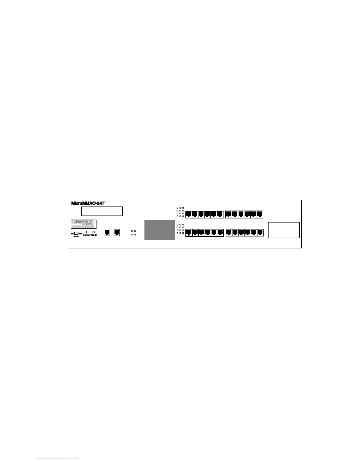
information, and operating instructions for the MicroMMAC-T (Figure
1-1) family of stackable hubs. Installing the MicroMMAC-T requires
familiarity with the physical layer components of Token Ring (IEEE
802.5) data communications networks.
NOTE
: Unless otherwise specified, this manual uses the term
MicroMMAC-T to collectively refer to the MicroMMAC-22T, the
MicroMMAC-24T, the MicroMMAC-42T, and the MicroMMAC-44T.
MicroMMAC-24T
LCD
16M4M
RESET
DISPLAY
SPEED
TOKEN RING HUB
SUPPORTING 100 OHM UTP CABLE
WITH
CPU
16 Mb/s
COM 1COM 2
LANVIEW®
ACT
MGMT
TPIM
Ring Out
RO
Slot
TPIM
.
24 23 22 21 20 19
12 11 10 9 8 7
18 17 16 15 14 13
RI
6 5 4 3 2 1
Figure 1-1. The MicroMMAC-T
1.1 CONTENTS OVERVIEW
This manual contains the following information:
Chapter 1,
describes features of the MicroMMAC-T and its add-on components. It
also lists sources where more information on Token Ring network
implementation can be found.
Chapter 2,
network guidelines, and MicroMMAC-T operating specifications.
Chapter 3,
and discusses network connections using various media types. This
chapter includes instructions for setting the Ring Speed Switch, the Reset
Switch, the NVRAM Switch, and the TPIM Phantom Switch. It also
Introduction
, outlines the contents of this manual and
Requirements/Specifications
Installation,
contains MicroMMAC-T installation instructions
, describes cabling requirements,
1-1
Page 10

INTRODUCTION
describes how to install a TPIM and concludes with installation check-out
instructions.
Chapter 4,
Local Management
, explains how to set up and use a
management terminal and a modem to access Local Management.
Chapter 5,
Troubleshooting
, explains how to monitor the operation
performance of the MicroMMAC-T using LANVIEW® LEDs and LCD’ s.
It also explains how to access POWER UP diagnostic test information.
1.2 MicroMMAC-T OVERVIEW
The MicroMMAC-T is an intelligent, stackable Multi-Media Access
Center providing connectivity and SNMP management for up to 255
Token Ring users (Local Management for up to 120 Token Ring users) in
remote office environments. The MicroMMAC-T can be used in
conjunction with Cabletron’s STH HubSTACK series of stackable
non-intelligent hubs.
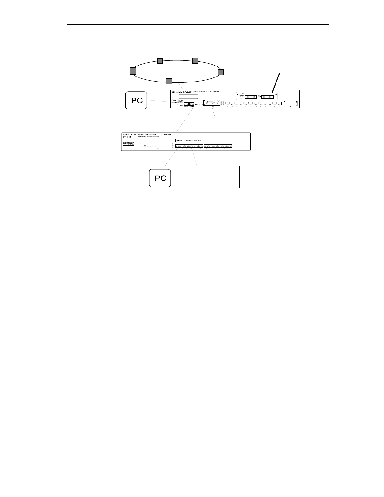
Figure 1-2 illustrates a typical MicroMMAC-T configuration scenario.
Attachable Bridge/Routing Interface Modules (BRIMs), incorporated as
seamless entities within the MicroMMAC-T , pro vide connectivity not only
to standard Token Rings but also to Ethernet, FDDI, ATM, and WAN
environments, depending upon the BRIM types used.
T oken Ring Port Interface Modules (TPIMs) attachable at the Ring In/Ring
Out (RI/RO) ports pro vide connectivity and expanded trunk connections to
a range of Token Ring media: Unshielded Twisted Pair (UTP), Shielded
Twisted Pair (STP), and Fiber.
By installing Cabletron’s MicroSNAC daughterboard in the
MicroMMAC-T, you can consolidate SNA/SDLC, BSC, LAN, and WAN
connectivity into a single unit.
Telnet support provides easy access to Local Management tools from any
TCP/IP based node on the network.
The MicroMMAC-T complies with the IEEE 802.5 standard and is fully
IBM Token Ring compatible. The remainder of this chapter discusses
MicroMMAC-T features in greater detail.
1-2
Page 11
INTRODUCTION
TOKEN RING
Telnet
UTP
WORKSTATION
Figure 1-2. Typical MicroMMAC-T Configuration Scenario
SDLC
All MicroMMAC-Ts are functionally and physically identical except for
the number and type of their T runk Connection Unit (TCU) lobe ports. The
following MicroMMAC-T configurations are available:
MicroMMAC-22T
•
: twelve active RJ45 TCU lobe ports that support
category 3, 4, and 5 UTP cabling.
•
MicroMMAC 24T
: twenty-four active RJ45 TCU lobe ports that
support category 3, 4, and 5 UTP cabling.
•
MicroMMAC-42T
: twelve active RJ45 TCU lobe ports that support
IBM Type 1, 2, 6, and 9 STP cabling.
•
MicroMMAC-44T
: twenty-four active RJ45 TCU lobe ports that
support IBM Type 1, 2, 6, and 9 STP cabling.
1.3 MicroMMAC-T FEATURES
NOTE
upgrade kit, the MicroSNAC device, BRIMs, TPIMs, interface cables, and
other accessories for the MicroMMAC-T.
: Call your Cabletron Sales representative to order the 12-port
1-3
Page 12

INTRODUCTION
Active TCU Ports
The active TCU ports regenerate, reshape, and filter the incoming signal,
permitting UTP lobe cable lengths of up to
lengths up to
150 meters
at 16 Mbps ring speed. The MicroMMAC-22T
120 meters
and STP lobe cable
and the MicroMMAC-42T can be upgraded in the field using the Cabletron
UTP and STP 12-port upgrade kits.
Cable Signal Polarity
Differential Manchester encoding is used for each concentrator module
TCU port. This permits passing data regardless of receive link polarity.
NOTE
: The MicroMMAC-T is not affected by the reversed polarity
condition. If, however, such a condition is discovered, the segment should
be removed fr om the network and wired corr ectly to avoid problems during
future network operations. Refer to Section 3.8 for cable pinouts
specifications
Speed Fault Protection
If a station attempts to insert into a ring port at a different speed from the
one set on the MicroMMAC-T, that port is automatically bypassed to
prevent the ring from beaconing. The Lobe Port Status LED blinks red (for
more information, see Section 5.1, USING LANVIEW LEDs) to indicate
that the port with the speed fault is being bypassed.
Local Management
Local Management provides you with the ability to manage the
MicroMMAC-T and all of its attached segments, including most BRIMs
and the MicroSNAC device. The CR BRIM-W/T and the MicroSNAC
provide their own configuration firmware.
Access Local Management by connecting an actual or emulated Digital
Equipment Corporation VT100™ series terminal to the MicroMMA C-T’ s
COM 1 port or the COM 2 port. To view diagnostic test information from
a display terminal, use the COM 2 port.
Token Ring Port Interface Modules (TPIMs)
TPIMs are modular connector cards used for expanding trunk connections
to a range of Token Ring media. TPIMs have embedded repeaters that
1-4
Page 13

INTRODUCTION
re-time all data. Cabletron offers a variety of TPIMs for RI/RO trunk
connections as shown in Table 1-1.
Table 1-1. TPIMs
TPIM Media T ype Connector
TPIM-T1 Shielded Twisted Pair DB9
TPIM-T2 Unshielded Twisted Pair RJ45
TPIM-T4 Shielded Twisted Pair RJ45
TPIM-F2 Multimode Fiber Optic ST
TPIM-F3 Single mode Fiber Optic ST
Ring Speed Switch
Use the Ring Speed Switch to select either 4 or 16 Mbps ring speed.
Flash EEPROM
The firmware image on the MicroMMAC-T can be upgraded by Flash
EEPROM downloads via Cabletron System’s Remote
LANVIEW/Windows version 2.3 or later, or via any server supporting
BOOTP or TFTP protocols.
LANVIEW LEDs
Cabletron Systems’ LANVIEW LEDs, located on the face of the
MicroMMAC-T, provide an effective monitoring and troubleshooting tool
to help diagnose power failures, RI/R O status, cable faults, ring speed, link
problems, and network activity. See Section 5.1 for information about
using LEDs.
Cabletron’s Distributed LAN Monitor Mode
To manage a network that includes multiple subnets, remote network
management stations need to query multiple management devices,
increasing the data traffic on the network. Network managers can reduce
the amount of management related traffic by setting the MicroMMAC-T
into Distributed LAN Monitor mode via a remote management package.
The MicroMMAC-T in DLM mode will collect management data from the
1-5
Page 14

INTRODUCTION
numerous management devices and serve as their management data
representative. The network management station then has to query only
one management device, the MicroMMAC-T in DLM mode, to access
management data for all management devices on the network.
Consult your network manager for DLM setup.
COM Port Applications
Both of the front panel COM ports are factory-configured to support Local
Management connections. Select among configuration options for Local
Management, Uninterruptible Power Supplies (UPS), the Serial Line
Internet Protocol (SLIP), and modems.
LCD and LCD Display Button
MicroMMAC-T’s front panel LCD used in conjunction with the LCD
display button provides you with comprehensi ve system-le vel information
such as power-up diagnostics, FLASH image re vision lev els, IP addresses,
and error alerts. See Section 5.2 for more information.
Reset Button
The Reset button on the front panel initializes the processor when pressed.
The information contained in NVRAM is retained after initialization. See
Section 3.5 for more information.
MIB Support
The MicroMMAC-T provides access to the following Management
Information Bases:
Standard MIBs
• MIB-2 (RFC 1231)
• IEEE RMON MIB (RFC 1271)
• RMON Extensions for Token Ring (RFC 1513)
Cabletron Enterprise MIBs
• Download
• MIB-II Extensions
1-6
Page 15

INTRODUCTION
• Token Ring FNB (Flexible Network Bus)
• DOT 5 Logical and Physical
• UPS (Uninterruptible Power Supply)
• Device
• DLM (Distributed LAN Monitor)
• PIC MIB (Product Information Chip MIB)
• Chassis MIB
RMON MIB Support
The MicroMMAC-T supports the RMON MIB RFC 1271/1513 Token
Ring Extensions shown in Table 1-2.
Table 1-2. RMON MIB RFC 1271/1513 Support
Group Subgroup Section
Statistics
rmon 1
History
rmon 2
Alarm
rmon 3
Host
rmon 4
Token Ring ML Stats Table
Token Ring P Stats Table
History Control Table
Token Ring ML History Table
Token Ring P History Table
Alarm Table alarm 1
Host Control Table
Host Table
Host Time Table
statistics 2
statistics 3
history 1
history 3
history 4
hosts 1
hosts 2
hosts 3
HostTopN
rmon 5
Matrix
rmon 6
HostTopN Control Table
HostTopN T able
Matrix Control Table
Matrix SD Table
Matrix DS Table
hostTopN 1
hostTopN 2
Matrix 1
Matrix 2
Matrix 3
1-7
Page 16

INTRODUCTION
Table 1-2. RMON MIB RFC 1271/1513 Support (Cont.)
Group Subgroup Section
Event
rmon 9
Token Ring
rmon 10
Event Table
Log Table
Ring Station Control Table
Ring Station Table
Ring Station Order Table
Ring Station Config Control Table
Ring Station Config Table
Source Routing Stats Table
event 1
event 2
Token Ring 1
Token Ring 2
Token Ring 3
Token Ring 4
Token Ring 5
Token Ring 6
1.4 STACKABLE CAPABILITIES
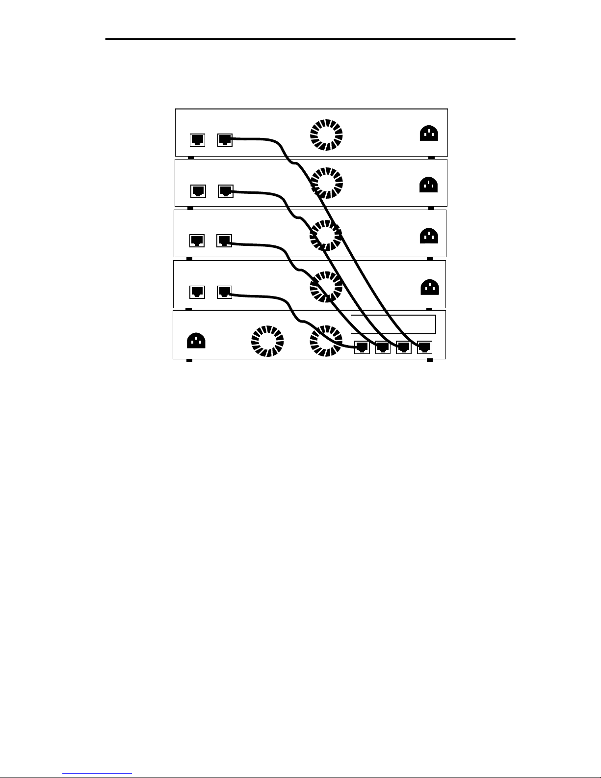
The MicroMMAC-T can be stacked with up to four HubSTACK STH
series non-intelligent hubs as shown in Figure 1-3. Four connectors are
available on the back panel of the MicroMMAC-T for connecting STH
12/24 type non-intelligent hubs. The MicroMMAC-T provides complete
management, including full packet and error statistics for the entire stack,
individual device, or individual port.
It is not necessary to power-of f the MicroMMA C-T to add or remov e hubs
from the stack.
1-8
Page 17
REAR VIEW
MicroMMAC Managing 4 Non-Intelligent Hubs
HubSTACK
STH-24
RESERVED
HubSTACK
STH-24
RESERVED
HubSTACK
STH-24
RESERVED
HubSTACK
STH-24
RESERVED
STACK
STACK
STACK
STACK
INTRODUCTION
MicroMMAC-24T
TOKEN RING HUB
WITH
LANVIEW®
BRIM Slot
STACK5STACK4STACK3STACK2
Figure 1-3. Typical Stackable Configuration
NOTE
: Token Ring HubSTACK Interface cables, which are used to
connect between the MicroMMAC-T and stacked STH hubs, are not
included with the MicroMMAC-T.
1.5 BRIDGING/ROUTING CAPABILITIES
A slot on the back panel of the unit provides installation access for BRIMs
to the hub. MicroMMA C-T management systems treat the installed BRIM
and the hub as a single entity. Cabletron offers the BRIMs listed in
Table 1-3.
1-9
Page 18

INTRODUCTION
.
Table 1-3. BRIMs
BRIM Description
BRIM-E6 Ethernet Connection
BRIM-W6 Wide Area Network (Full or Fractional T1; 56k DDS)
BRIM-A6 Asynchronous Transfer Mode Connection
BRIM-T6 Token Ring Connection
CR BRIM-W/T Cisco WAN BRIM for Token Ring
BRIM-FO Fiber Distributed Data Interface Connection
1.5.1 SNA/WAN Integration
The MicroSNA C add-on daughterboard pro vides two ports, both of which
can be used to provide con version from SNA/SDLC or BSC links to LLC2.
The MicroSNAC can operate in a converter mode or as a WAN
concentrator.
1.6 REMOTE MANAGEMENT CAPABILITIES
The MicroMMAC-T may be managed through any Simple Network
Management Protocol (SNMP) software. Cabletron Systems offers the
following remote management packages:
• Cabletron Systems SPECTRUM
• Cabletron Systems Remote LANVIEW®/Windows™
• Cabletron Systems Remote SPECTRUM
Applications
®
®
Portable Management
1.7 TELNET CAPABILITIES
The MicroMMAC -T supports Telnet, which allows any TCP/IP based
node on the network to establish a Local Management session with the
1-10
Page 19

INTRODUCTION
module. This feature complements the remote SNMP management and
allows for quick hub configuration changes or checks.
1.8 RECOMMENDED READING
The following publications provide more information on Token Ring
network implementation.
Local Area Networks, Token Ring Access Method
, IEEE Standard 802.5
(1989)
Commercial Building Wiring Standard, EIA/TIA-568
LAN Troubleshooting Handbook
, Mark Miller (1989, M&T Publishing)
1.9 GETTING HELP
For additional support related to the Cabletron Systems MicroMMAC-T,
or for any questions, comments, or suggestions concerning this manual,
contact Cabletron Systems Technical Support:
By phone. . . . . . . . . . . . . . . . . . (603) 332-9400
Monday-Friday; 8am - 8pm EST
®
By CompuServe
By Internet mail . . . . . . . . . . . . support@ctron.com
. . . . . . . . . . . GO CTRON from any ! prompt
By BBS. . . . . . . . . . . . . . . . . . . (603) 337-3750
By mail . . . . . . . . . . . . . . . . . . . Cabletron Systems, Inc.
P.O. Box 5005
Rochester, NH 03866-5005
1-11
Page 20
CHAPTER 2
REQUIREMENTS/SPECIFICATIONS
Read this chapter prior to installing the MicroMMAC-T. It contains
operating specifications and requirements for power and cabling. To obtain
satisfactory performance from this equipment, networks must meet the
requirements and conditions specified in this chapter. Failure to follow
these guidelines may result in poor network performance.
2.1 CABLE SPECIFICATIONS
Token Ring architecture provides for a set of Trunk Coupling Units
(TCUs) connected by trunk cabling. To extend the trunk cabling, install
TPIMs into the MicroMMAC-T’s RI/RO ports. TPIMs have embedded
repeaters and provide trunk connections for UTP, STP, Multimode Fiber,
and Single Mode Fiber cabling.
Attach stations to the TCU lobe ports with lobe cabling. Figure 2-1 shows
a typical ports to cables configuration.
Ring Out TPIM
TOKEN RING HUB WITH LANVIEW®
MicroMMAC-24T
SUPPORTING 100 OHM STP CABLE
18 17 16 15 14 13
24 23 22 21 20 19
6 5 4 3 2 1
12 11 10 9 8 7
RO
TCU Lobe Ports
Ring In TPIM
18 17 16 15 14 13
ACT
MGMT
24 23 22 21 20 19
6 5 4 3 2 1
12 11 10 9 8 7
RO RI
RI
Trunk Cabling
Token Ring Station
DISPLAY
16M4M
RESET
DISPLAY
SPEED
COM 1COM 2
Lobe Cabling
TOKEN RING HUB WITH LANVIEW®
MicroMMAC-24T
SUPPORTING 100 OHM STP CABLE
DISPLAY
16M4M
RESET
DISPLAY
SPEED
ACT
CPU
MGMT
16 Mb/s
CPU
16 Mb/s
COM 1COM 2
Figure 2-1. MicroMMAC-T Ports/Cables
2-1
Page 21

REQUIREMENTS/SPECIFICATIONS
2.1.1 UTP Cable Specifications
The MicroMMAC-22T and MicroMMAC-24T lobe ports and the
TPIM-T2 support voice grade Unshielded Twisted Pair (UTP) cable, as
described in specifications for EIA/TIA TSB 568 and IBM Type 3 cable.
UTP consists of four pairs of 24 AWG solid wire for data or voice
communication and is typically used to wire cable runs within building
walls. In some installations, existing UTP building wiring can be used for
Token Ring cabling. UTP cable must conform to the limits shown in
Table 2-1.
WARNING
: DO NOT connect UTP cabling to any non-Token Ring
network conductors (telephone, etc.) or ground. If in doubt, test wiring
before using. The voltages used in UTP telephone cir cuits present a shock
hazard and can damage Token Ring equipment when connected to Token
Ring cabling.
The increased popularity and cost advantages of UTP cable have driven
refinements in UTP cable design. Better grades of UTP cable, known as
supergrade or level 4, provide improved transmission characteristics and
may allow operation at 16 Mbps on longer lobe cables.
Attenuation and Impedance
The values listed in Figure 2-1 include the maximum attenuation of the
cables, connectors, patch panels, and reflection losses due to impedance
mismatches in the segment.
Table 2-1. UTP Voice Grade and Category 3 Specifications
Frequency Impedance Attenuation
1 MHz 100Ω ±15% <26 dB/km (8 dB/1000 ft)
4 MHz 100Ω ±15% <56 dB/km (16 dB/1000 ft)
10 MHz 100Ω ±15% <98 dB/km (30 dB/1000 ft)
16 MHz 100Ω ±15% <131 dB/km (40 dB/1000 ft)
2-2
Page 22

REQUIREMENTS/SPECIFICATIONS
Maximum Lobe Lengths
Lobe length is the physical length of the cable connecting a station to its
TCU port at the MicroMMAC-T. Table 2-2 lists the maximum lobe cable
length for ring speeds of 4 and 16 Mbps. The values listed refer to total
lengths made up of UTP cable only.
Table 2-2. UTP Maximum Lobe Lengths
UTP Cable Type Maximum Lobe Length
4 Mbps 16 Mbps
Category 3 200 meters 100 meters
(656 feet) (328 feet)
Category 4 200 meters 100 meters
(656 feet) (328 feet)
Category 5 250 meters 120 meters
(820 feet) (394 feet)
Type 3 Media Filters
A Type 3 Media Filter is required when connecting a UTP lobe segment
from a MicroMMAC-22T or MicroMMAC-24T to a station supporting
STP cabling. Cabletron Systems offers the follo wing Type 3 Media Filters:
• TRMF , RJ45 (UTP) connector to 10-inch DB9 (STP) cable with
LANVIEW
• TRMF-2, RJ45 (UTP) connector to DB9 (STP) connector
Maximum Number of Stations
When UTP lobe cabling is used in any ring segment, the number of ring
stations supported by the MicroMMAC-T is limited to 150, regardless of
the operating ring speed.
2-3
Page 23

REQUIREMENTS/SPECIFICATIONS
2.1.2 STP Cable Specifications
MicroMMACs 42T and 44T and TPIMs T1 and T4 support IBM Type 1,
2, 6, and 9 STP cabling as described below:
• IBM T ype 1: Two STP lengths of 22 AWG solid wire for data. Used
for the longest cable runs within building walls of buildings.
• IBM T ype 2: Similar to Type 1 data cable, but having four additional
UTP lengths of 22 A WG solid wire carried outside of the shield casing.
Typically used for voice communication and often used to wire cable
runs within the walls of buildings.
• IBM T ype 6: Two STP lengths of 26 AWG stranded wire for data.
Used in patch panels or to connect devices to/from wall jacks.
Attenuation for Type 6 cable is 3/2 x Type 1 cable (66 m of Type 6
=100 meters of Type 1).
• IBM T ype 9: Similar to Type 1, but uses 26 AWG solid wire.
Attenuation for Type 9 cable is 3/2 x Type 1 cable (66 m of Type 9
= 100 meters of Type 1).
Attenuation and Impedance
The attenuation values shown in Table 2-3 include the attenuation of the
cables, connectors, patch panels, and reflection losses due to impedance
mismatches in the segment
.
Table 2-3. STP Cable Specifications
Types Frequency Impedance Attenuation
1 & 2 4 MHz
16 MHz
6 & 9 4 MHz
16 MHz
150Ω + 15%
150Ω + 15%
150Ω + 15%
150Ω + 15%
<22 dB/km (6.7 db/1000 ft.)
<45 dB/km (13.7 db/1000 ft.)
<33 dB/km (10 db/1000 ft.)
<66 dB/km (20 db/1000 ft.)
Maximum Lobe Lengths
The lobe length is the physical length of the cable connecting a station to
its TCU port at the MicroMMAC-T. Table 2-4 lists the maximum lobe
2-4
Page 24

REQUIREMENTS/SPECIFICATIONS
cable length for ring speeds of 4 and 16 Mbps. The cable lengths listed in
Table 2-4 refer to total lengths made up of STP cable only
.
Table 2-4. STP Maximum Lobe Lengths
STP Cable Type Ring Speed
4 Mbps 16 Mbps
IBM Types 1 & 2 300 meters 150 meters
(984 feet) (492 feet)
IBM Types 6 & 9 (only for
station to wall jack and patch
panels)
30 meters 30 meters
(99 feet) (99 feet)
Maximum T runk Lengths
The maximum trunk cable length between the MicroMMAC-T and other
active devices is equal to the maximum drive distance as shown in
Table 2-5. For passive devices, the combined length of twice the longest
trunk cable, plus the longest lobe cable attached to the passive ring
segment cannot exceed the Maximum Drive Distance.
Table 2-5. STP Maximum Drive Distance
STP Cable Type Ring Speed
4 Mbps 16 Mbps
IBM Types 1 & 2 770 meters 346 meters
IBM Types 6 & 9 513 meters 230 meters
Maximum Number of Stations
If only STP lobe cabling is used throughout the ring, the MicroMMAC-T
supports up to 255 ring stations, regardless of ring speed.
(2525 feet) (1138 feet)
(1683 feet) (755 feet)
2-5
Page 25

REQUIREMENTS/SPECIFICATIONS
Mixed Cable Types
If multiple cable types exist in network, compensations must be made for
the different cable attenuations. Type 6 and T ype 9 cables can run only 2/3
the distance of T ype 1. Therefore 10 meters of T ype 1 ≈ 6.6 meters of T ypes
6 and 9.
2.1.3 Multimode Fiber Optic Cable Specifications
Table 2-6 shows specifications for the Multimode Fiber Optic Cable
supported by TPIM-F2
.
Table 2-6. Multimode Fiber Optic Cable Specifications
Cable Type Attenuation Maximum Drive Distance
50/125 µm 13.0 dB or less
62.5/125 µm 16.0 dB or less
The maximum allowable fiber
optic cable length is 2 km
(2187.2 yards). However, IEEE
100/140 µm 19.0 dB or less
802.5 specifications allow for a
maximum of 1 km (1093.6
yards).
Maximum T runk Lengths
The maximum trunk cable length between the MicroMMAC-T and other
active devices is equal to the maximum drive distance as shown in
Table 2-6. For passive devices, the combined length of twice the longest
trunk cable, plus the longest lobe cable attached to the passive ring
segment, must not exceed the Maximum Drive Distance Trunk Length.
Attenuation
Fiber optic cable must be tested with an attenuation test set adjusted for an
850 nm wavelength. This test ensures that a cable’s signal loss is within
acceptable limits. Table 2-6 shows the attenuation for each Multimode
cable type.
2-6
Page 26

REQUIREMENTS/SPECIFICATIONS
Fiber Optic Budget
The fiber optic delay budget, which determines the fiber optic cable’s
maximum length, should be calculated and taken into consideration in the
network design stage. Fiber optic delay budget is determined by summing
the optical signal loss due to fiber optic cable attenuation, in-line splices,
and fiber optic connectors.
2.1.4 Single Mode Fiber Optic Cable Specifications
Table 2-7 shows specifications for the Single Mode Fiber Optic Cable
supported by TPIM-F3.
Table 2-7. Single Mode Fiber Optic Cable Specifications
Cable Type Attenuation Maximum Drive Distance
8/125-12/125 µm 10.0 dB or less The max. allowable fiber optic
cable length is 10 km (10936
yards). However, IEEE 802.5
specs allow for a max. of 1 km
(1093.6 yards).
Maximum T runk Lengths
The maximum trunk cable length between the MicroMMAC-T and other
active devices is equal to the Maximum Drive Distance as shown in
Table 2-7. For passive devices, the combined length of twice the longest
trunk cable plus the longest lobe cable attached to the passive ring se gment
must not exceed the Maximum Drive Distance Trunk Length.
Attenuation
Fiber optic cable must be tested with an attenuation test set adjusted for a
1300 nm wavelength. This test ensures that the cable’ s signal loss is within
an acceptable range of 10 dB or less for any giv en single mode fiber optic
link.
2-7
Page 27

REQUIREMENTS/SPECIFICATIONS
Fiber Optic Budget
The fiber optic delay budget, which determines the fiber optic cable’s
maximum length, should be calculated and taken into consideration in the
network design stage. Fiber optic delay budget is determined by summing
the optical signal loss due to fiber optic cable attenuation, in-line splices,
and fiber optic connectors.
2.2 CABLE RECOMMENDATIONS/TROUBLESHOOTING
The following sections describe common cable problems and
recommendations for correcting them.
Crosstalk
Crosstalk is interference caused by signal coupling between different cable
pairs contained within a multi-pair cable bundle. Multi-pair cables should
not be used for UTP lobe cabling. UTP lobe cabling should be dedicated
to carrying T oken Ring traf fic. A void mixing T oken Ring signals with other
applications (voice, etc.) within the same cable.
Noise
Noise can be caused by crosstalk or externally imposed impulses. If
noise-induced errors are suspected, ensure that the electrical wiring in the
area is properly wired and grounded and/or try re-routing cabling away
from potential noise sources (motors, switching equipment, fluorescent
lighting, high amperage equipment).
Temperature
The attenuation of PVC-insulated cable varies significantly with
temperature. Check the cable manufacturer’ s specifications. Plenum-rated
cables are strongly recommended in areas where temperatures exceed
40˚C. Under such conditions, plenum-rated cables ensure that cable
attenuation remains within specifications.
2-8
Page 28

REQUIREMENTS/SPECIFICATIONS
Other Considerations
In addition to complying with the preceding cable specifications, the
following recommendations should be followed to minimize errors and
obtain optimum performance from the network:
• UTP cabling should be free of splices, stubs, or bridged taps.
• Maintain a two punch-down block limit between TCU ports and wall
outlets.
• Properly ground metal troughs, ducts, etc. carrying Token Ring
signals.
• Avoid routing Token Ring signals near copper cables that exit a
building or are susceptible to lightning strikes and power surges.
• UTP cables containing Token Ring signals should not be
simultaneously used for applications which may impress high voltages
(greater that 5 volts) with sharp rise or fall times. The noise coupling
from such signals could directly cause errors on the Token Ring
network.
• Lobe lengths between TCU ports and connected devices should not
exceed 100 meters of 22 to 24 AWG wire.
• Wherever possible, use dedicated UTP cable for Token Ring signals.
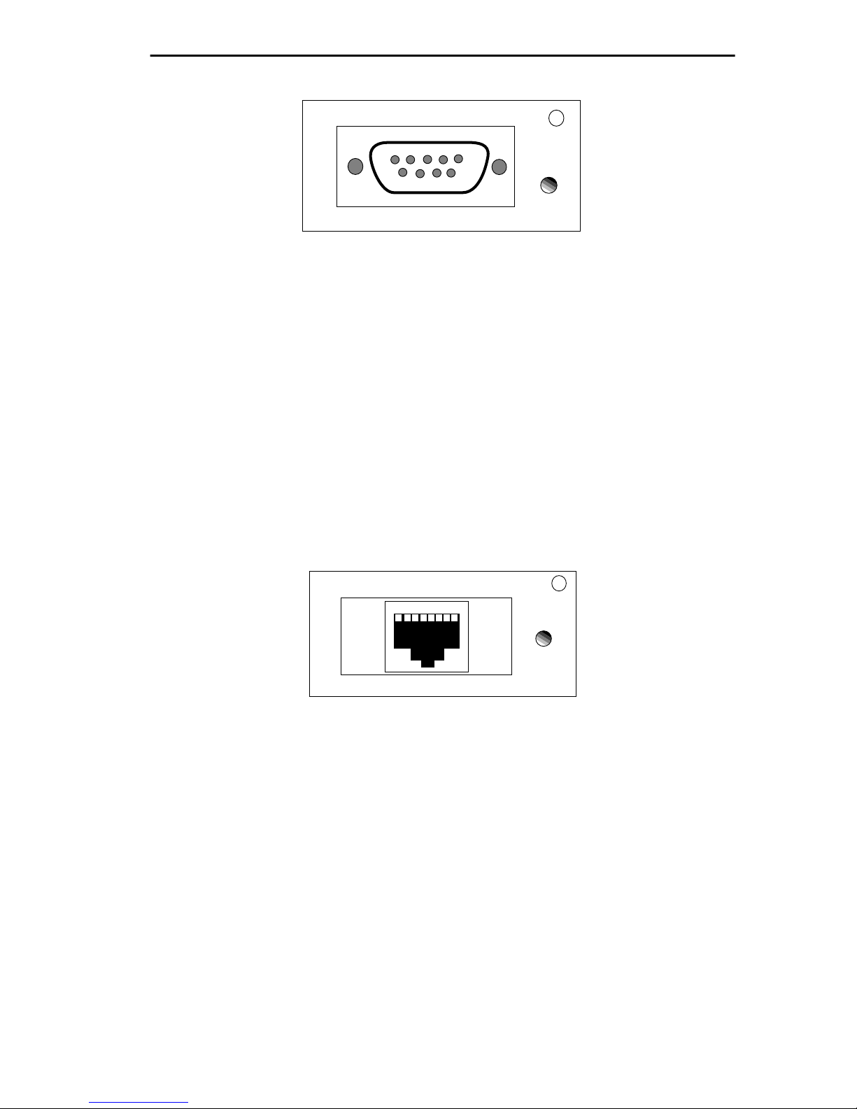
2.3 COM PORT SPECIFICATIONS
The RJ45 COM 1 and COM 2 ports (Figure 2-2) support Local
Management applications. A description of COM port applications is
listed below:
MicroMMAC-24T
16M4M
DISPLAY
SPEED
RESET
COM 2
TOKEN RING HUB
SUPPORTING 100 OHM UTP CABLE
COM 1
WITH
LANVIEW®
Figure 2-2. COM 1/COM 2 Ports
2-9
Page 29

REQUIREMENTS/SPECIFICATIONS
Local Management
Both COM 1 and COM 2 ports are factory-configured to support Local
Management access by an actual or emulated Digital Equipment
Corporation VT 100™ terminal.
Booting/Diagnostics
Terminal display of POWER UP booting/diagnostic tests available only
when terminal is connected to COM 2 (for information about Boot
sequences, see Section 5.3 ).
UPS
COM 2 supports Uninterruptible Power Supply (American Power
Conversion only).
SLIP
Both COM ports support Serial Line Internet Protocol (SLIP).
Modem
Both COM ports support modem connection.
2.4 TPIM SPECIFICATIONS
TPIMs provide Ring In/Ring Out (RI/R O) connections that can extend the
network through a variety of media. Each TPIM has an embedded repeater
that re-times all data.
The LNK (Link) LED on each TPIM provides the following information:
• Green - RI or RO active
• Red (TPIM-T1/T2/T4 only) - No Link (Autowrapped)
• Off - No Link (Wrapped or Disabled)
TPIM-T1
TPIM-T1 provides a female DB9 connector that supports STP cabling.
Figure 2-3 shows TPIM-T1 pinouts for Ring Out and Ring In applications.
2-10
Page 30
REQUIREMENTS/SPECIFICATIONS
5 4 3 2 1
9 8 7 6
LNK
TPIM-T1
RING OUT
1. Transmit +
2. Ground
3. +5V at 250 mA
4. Ground
5. Receive -
6. Transmit -
7. Ground
8. Ground
9. Receive +
RING IN
1. Receive +
2. Ground
3. +5V at 250 mA
4. Ground
5. Transmit -
6. Receive -
7. Ground
8. Ground
9. Transmit +
Figure 2-3. TPIM-T1 Pinouts
TPIM-T2
TPIM-T2 provides an RJ45 connector that supports UTP cabling.
Figure 2-4 shows pinouts for Ring Out and Ring In applications.
1 2 3 4 5 6 7 8
LNK
TPIM-T2
RING OUT
1. Not Used
2. Not Used
3. Receive -
4. Transmit +
5. Transmit -
6. Receive +
7. Not Used
8. Not Used
RING IN
1. Not Used
2. Not Used
3. Transmit -
4. Receive +
5. Receive -
6. Transmit +
7. Not Used
8. Not Used
Figure 2-4. TPIM-T2 Pinouts
TPIM-T4
TPIM-T4 is an RJ45 connector that supports STP cabling. Figure 2-5
shows pinouts for Ring Out and Ring In applications.
2-11
Page 31

REQUIREMENTS/SPECIFICATIONS
1 2 3 4 5 6 7 8
RING OUT
1. Not Used
2. Not Used
3. Receive -
4. Transmit +
5. Transmit -
6. Receive +
7. Not Used
8. Not Used
RING IN
1. Not Used
2. Not Used
3. Transmit -
4. Receive +
5. Receive -
6. Transmit +
7. Not Used
8. Not Used
LNK
TPIM-T4
Figure 2-5. TPIM-T4 Pinouts
TPIM-F2
TPIM-F2, shown in Figure 2-6, provides an ST connector that supports
Multimode fiber Optic cabling.
RX
TX
LNK
TPIM-F2
Figure 2-6. TPIM-F2
NOTE: Transmitter power and receive sensitivity levels, shown in
Table 2-8, are Peak Power Levels after optical overshoot. A Peak Power
Meter must be used to correctly compare the values given to those
measured on any particular port. If power levels are being measured with
an Average Power Meter, then 3 dBm must be added to the measurement
to correctly compare those measured values to the values listed (i.e. -30.5
dBm peak=-33.5 dBm average).
2-12
Page 32

REQUIREMENTS/SPECIFICATIONS
.
Table 2-8. TPIM-F2 Specifications.
Parameter
Receive
Typical
V alue
Worst Case
-30.5 dBm -28.0 dBm — —
Worst Case
Budget
Typical
Budget
Sensitivity
Peak Input
-7.6 dBm -8.2 dBm — —
Power
Transmitter Power:
50/125 µm -13.0 dBm -15.0 dBm 13.0 dB 17.5 dB
62.5/125 µm -10.0 dBm -12.0 dBm 16.0 dB 20.5 dB
100/140 µm -7.0 dBm -9.0 dBm 19.0 dB 23.5 dB
Error Rate: Better than 10
-10
TPIM-F3
TPIM-F3, shown in Figure 2-7, is an ST connector that supports Single
Mode fiber Optic cabling.
RX
TX
LNK
TPIM-F3
Figure 2-7. The TPIM-F3
Table 2-9. TPIM-F3 Specifications
Parameter Typical Minimum Maximum
Transmitter
1300 nm 1270 nm 1330 nm
Peak W a v e Length
Spectral Width 60 nm – 100 nm
Rise Time 3.0 nsec 2.7 nsec 5.0 nsec
2-13
Page 33

REQUIREMENTS/SPECIFICATIONS
C
Table 2-9. TPIM-F3 Specifications
Parameter Typical Minimum Maximum
Fall Time 2.5 nsec 2.2 nsec 5.0 nsec
Duty Cycle 50.1% 49.6% 50.7%
Bit Error Rate: Better than 10
-10
NOTE: Transmitter Power decreases as temperatures rise and increases
as temperatures fall. Use the Output Power Coefficient to calculate
increased or decreased power output for an operating environment. For
°
example, the typical power output at 25
For a 4
°
C temperature increase, multiply the typical coefficient
C is -16.4 dBm.
(-0.15 dBm) by four and add the result to typical output power
(4 x -0.15 dBm + -16.4 = -17.0).
Maximum Sensitivity (-36.0)
Receive
Sensitivity
Maximum
Receive
Input Power
Typical Sensitivity (-31.0)
Minimum Sensitivity (-30.0)
Minimum Receive Input (-9.72)
Typical Receive Input (-7.5)
Maximum Receive Input (-6.99)
Transmitter Power*
(At 25°C into
8.3/125µm fiber)
dBm
* Transmit Power Typical Power Minimum Power Maximum Power
Coefficient
(See Note Below)-0.15dBm/ °C -0.12 dBm/ °C-0.18 dBm/ °
-40 -35 -30 -25 -20 -15 -10 -5 0
Less Power
NOTE: The transmitter power levels provided above are Peak Power
Levels after optical overshoot. Use a Peak Power Meter to correctly
compare the values given to those measured on any particular port.
When measuring power levels with an Average Power Meter, add 3 dBm
2-14
Maximum Transmit Power (-12.0)
Typical Transmit Power (-15.5)
Minimum Transmit Power (-21.0)
More Power
Page 34

REQUIREMENTS/SPECIFICATIONS
to the average power measurement to correctly compare the average power
values measured to the values listed above (i.e., -33.5 dBm average + 3 dB
= -30.5 dBm peak).
2.5 GENERAL SPECIFICATIONS
Cabletron Systems reserves the right to change the following operating
specifications at any time without notice:
• Data Buffer Memory (RAM): 8 MB (Upgradeable)
• Internal Processor: Intel 80C960CF at 24 MHz
• Controller: Texas Instruments TMS380C26
• Static RAM: 128 KB with battery back-up
• EPROM: 128 KB
• FLASH MEMORY: 2 MB (Upgradeable)
2.5.1 Power Supply Requirements
NOTE: The MicroMMAC-T has a universal power supply which will
accept input power between 85 and 264 VAC, 47-63 Hz.
The power supply has two outputs of +5 volts and +12 volts. Maximum
output power is 125 watts and the minimum efficiency is 65% under all
conditions of line at full load. The minimum and maximum load current
from each output is shown below.
Table 2-10.
Output Min. Load Max. Load Max Power
+ 5 Volts 1.00 Amps 15 Amps 75 Watts
+12 Volts 0.15 Amps 4 Amps 48 Watts
2.5.2 Environmental Requirements
Operating Temperature: +5° to +50°C
2-15
Page 35

REQUIREMENTS/SPECIFICATIONS
Non-operating Temperature: -30° to +90°C
Operating Humidity: 5 to 95% (non-condensing)
2.5.3 Safety
This unit meets the safety requirements of UL 1950, CSA C22.2
No. 950 and EN 60950; the EMI requirements of FCC Class A and
EN 55022 Class A; and the EMC requirements of EN 50082-1.
WARNING: It is the responsibility of the system vendor to ensur e that the
total system, including the MicroMMAC-T, meets allowed limits of
conducted and radiated emissions.
2.5.4 Physical
Dimensions:
2.8H x 17.0W x 13.5D inches
(7.2H x 43.6W x 34.6D cm)
Weight:
Unit: 7 pounds
Shipping: 11 pounds
2.5.5 Service
MTBF >944,197 hours projected
MTTR <0.5 hour
2-16
Page 36

CHAPTER 3
INSTALLATION
This chapter outlines MicroMMAC-T installation and netw ork connection
procedures. Be sure that the network meets the guidelines and
requirements outlined in Chapter 2, Requirements/Specifications, before
installing the MicroMMAC-T.
3.1 UNPACKING THE MicroMMAC-T
Unpack the module carefully. Preserve and save all packaging materials
for possible storage or transport of the MicroMMAC-T.
Thoroughly inspect the MicroMMAC-T immediately. If there are any
signs of damage to the module, contact Cabletron Systems Technical
Support immediately.
3.2 ATTACHING THE STRAIN RELIEF BRACKET
Attach the strain relief bracket to the front of the MicroMMAC-T as
described:
1. From the MicroMMAC-T installation kit, locate the strain relief
bracket (shown in Figure 3-1) and four 8-32 x 3/8” screws.
CAUTION: Use of longer screws may cause damage to the unit or
electrical shock.
2. Attach the strain relief bracket to the bottom of the MicroMMAC-T as
shown in Figure 3-1.
3-1
Page 37

INSTALLATION
TOKEN RING HUB
WITH
MicroMMAC-24T
SUPPORTING 100 OHM STP CABLE
LANVIEW®
Figure 3-1. Attaching the Strain Relief Bracket
3.3 INSTALLING THE MicroMMAC-T
The MicroMMAC-T can be rack-mounted, wall-mounted, or placed on
any horizontal surface. Refer to the following subsections for the
appropriate installation instructions. When installing the MicroMMAC-T
into something other than a 19-inch rack, installation requires the
following:
• An unrestricted free surface area at least 21 inches wide, 18 inches
deep, and 6 inches high.
• A single phase 85 to 264 V ac, 15A, grounded po wer receptacle located
within 7 feet of the site.
• If a shelving unit is used, it must be able to support 30 pounds of static
weight.
• The temperature in selected location must be between 5° and 50°C,
and change less than 10°C per hour.
NOTE: Be sure that the selected location is within reach of the network
cabling.
3.3.1 Rack-Mounting the MicroMMAC-T
Refer to Figure 3-2 and perform the following steps to install the
MicroMMAC-T in a 19-inch rack:
1. Remove the four cover screws located along the front edges of each
side of the MicroMMAC-T.
3-2
Page 38

INSTALLATION
2. Using the four cover screws removed in step 1, attach the
rack-mounting brackets to each end of the MicroMMAC-T.
Wall/Rack Mounting
Brackets (2)
TOKEN RING HUB
WITH
MicroMMAC-24T
SUPPORTING 100 OHM STP CABLE
LANVIEW®
Screws (4)
Figure 3-2. Installing of Rack-Mount Brackets
3. With the mounting brackets installed, position the MicroMMAC-T
between the vertical frame members of the 19-inch rack and fasten it
securely with the mounting screws (see Figure 3-3).
19-Inch Rack
TOKEN RING HUB
WITH
MicroMMAC-24T
SUPPORTING 100 OHM STP CABLE
LANVIEW®
Screws (4)
Figure 3-3. Installing the MicroMMAC-T in a 19-inch Rack
3.3.2 Wall-Mounting the MicroMMAC-T
When wall-mounting the MicroMMAC-T, the TCU ports must face
downward. Perform the following steps to wall-mount the
MicroMMAC-T:
NOTE: 1/4-inch Molly screw anchors for wall-mounting are not included
with the MicroMMAC-T.
1. Use the supplied screws to attach the wall-mounting brackets to the
bottom of the MicroMMAC-T as shown in Figure 3-4. There are two
brackets, one for each side.
3-3
Page 39

INSTALLATION
Molly Screw
Anchors
Bracket Screws
Molly Screws
Wall Mounting Bracket
Figure 3-4. Wall-Mounting the MicroMMAC-T
2. Select a wall location within seven feet of a power outlet for the
MicroMMAC-T.
WARNING: When drilling pilot holes, any electrical wiring inside the
wall may present a potential SHOCK HAZARD. Select a wall location
accordingly.
3. Position the MicroMMAC-T against the wall with the network port
facing down. Using a pencil, mark the wall location for the four pilot
holes.
4. Set the MicroMMAC-T aside and carefully drill four 1/4” pilot holes,
(one for each of the Molly screw anchors) and insert the four Molly
screw anchors into the holes.
5. Place a screw in each anchor, and tighten until each anchor expands
firmly in the wall; then remove the screws completely.
6. Position the MicroMMAC-T on the wall ov er the anchors and reinstall
the four screws to attach the MicroMMAC-T to the wall, as shown in
Figure 3-4. Tighten the four screws.
3-4
Page 40

INSTALLATION
3.3.3 Free-Standing Installation
For a free-standing shelf or table top installation, locate the
MicroMMAC-T, as shown in Figure 3-5, within 7 feet of its power source
on an unrestricted free surface area 21 inches wide, 18 inches deep, and 6
inches high.
18 IN.
21 IN.
TOKEN RING HUB
WITH
SUPPORTING 100 OHM STP CABLE
LANVIEW®
MicroMMAC-24T
6 IN.
Max. Dist. 7 FT.
Figure 3-5. Free-Standing Installation
3.4 CONNECTING TO A POWER SOURCE
NOTE: The Micr oMMAC-T has a universal power supply that allows it to
use power sources from 85 Vac to 264 Vac, 47-63 Hz.
To connect the MicroMMAC-T to the power source, plug the power cord
into a grounded wall outlet. After the MicroMMAC-T runs a self test, the
CPU LED blinks green to indicate normal operation. If the LED remains
red, the processor is faulty.
3.5 RESETTING THE MICROMMAC-T
The MicroMMAC-T reset b utton is located on the left front panel as shown
in Figure 3-6.
3-5
Page 41

INSTALLATION
To reset the MicroMMAC-T:
Insert a small pointed-tip object (e.g., ballpoint pen) into the recessed reset
button hole, press the button once, and then release.
TOKEN RING HUB
WITH
MicroMMAC-24T
4 Mb 16 Mb
SPEED
RESET BUTTON
RESET SWITCH
Figure 3-6. The Reset Button
SUPPORTING 100 OHM STP CABLE
LANVIEW®
3.6 SETTING THE RING SPEED
The ring speed switch is located on the front face of the MicroMMAC-T
as shown in Figure 3-7.
The MicroMMAC-T’s factory-default ring speed setting is 16 Mbps.
To change the ring speed:
1. Slide the ring speed switch to the desired setting.
2. RESET the MicroMMAC-T.
3. Check that the Ring Speed LED indicates the correct setting.
3-6
Page 42

MicroMMAC-24T
4 Mb 16 Mb
SPEED
TOKEN RING HUB
SUPPORTING 100 OHM STP CABLE
WITH
INSTALLATION
LANVIEW®
4 Mb 16 Mb
SPEED
On = 16 Mbps
Off = 4 Mbps
Figure 3-7. The Ring Speed Switch
3.7 SETTING THE NVRAM SWITCH
Figure 3-8 shows the location of the NVRAM Reset Switch. It can be
reached by a inserting a small screwdri ver through the side vent. NVRAM
(Non-Volatile Random Access Memory) stores user-entered parameters
such as IP address and device name.
Ring Speed LED Indicator
MicroMMAC-24T
TOKEN RING HUB
SUPPORTING 100 OHM STP CABLE
WITH
LANVIEW®
Figure 3-8. NVRAM Reset Switch Location
To restore MicroMMAC-T parameters to the factory defaults:
1. With power-ON, toggle the NVRAM switch from one position to the
other.
NVRAM
RESET SWITCH
IN HERE
3-7
Page 43

INSTALLATION
2. Press the MicroMMAC-T’s Reset button.
Once the module is reset, use the factory-default settings or enter new
parameters. The MicroMMAC-T stores these settings in NVRAM
during normal operation and during power do wn until the reset switch
is toggled again.
NOTE: Clearing and resetting NVAM does not reset the date and time.
3.8 CONNECTING LOBE PORT CABLING
The MicroMMACs 22T and 24T have unshielded RJ45 lobe ports that
support UTP cabling. T o connect a UTP segment from the MicroMMA C-T
to a station supporting STP cabling, a Type 3 Media Filter is required. The
Cabletron Systems TRMF and TRMF-2 are available for this purpose.
The MicroMMACs 42T and 44T have shielded RJ45 lobe ports that
support STP cabling. Shielded patch cables that adapt a shielded RJ45 to a
data connector (MIC) are available from Cabletron Systems (PN
9372057-8). These adapter/patch cables allow connection to an existing
patch panel equipped with data connectors. The MicroMMAC-T’s
network lobe port pinouts are shown in Figure 3-9.
RJ45 Plug
18
RJ45 Plug to MIC Connector
Black
Orange
Green
Blue
MIC Connector
Pin 3 (Receive -) . . . . . . . . .to . . . Green (Transmit -)
Pin 4 (Transmit +). . . . . . . . .to . . . Orange (Receive +)
Pin 5 (Transmit -) . . . . . . . . .to . . . Black (Receive -)
Pin 6 (Receive +) . . . . . . . . .to . . . Blue (Transmit +)
3-8
Page 44

INSTALLATION
RJ45 Plug
18
RJ45 Plug
RJ45 Plug to RJ45 Plug
(at TCU) (at device port)
Pin 3 (Receive -) . . . . . . . . . to. . . . Pin 3 (Transmit -)
Pin 4 (Transmit +) . . . . . . . . to. . . . Pin 4 (Receive +)
Pin 5 (Transmit -). . . . . . . . . to. . . . Pin 5 (Receive -)
Pin 6 (Receive +). . . . . . . . . to. . . . Pin 6 (Transmit +)
Figure 3-9. Network lobe pinouts
18
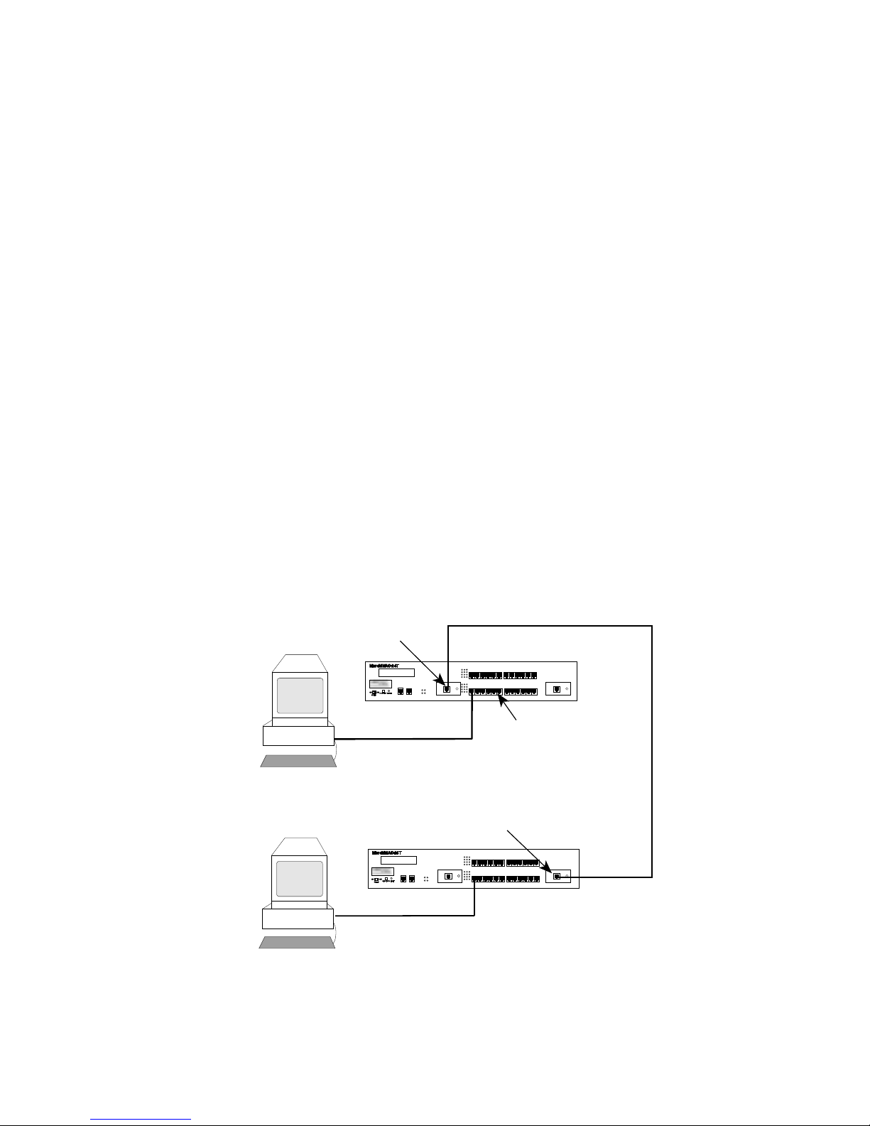
Figure 3-10 and Figure 3-11 illustrate possible MicroMMAC-T cabling
configurations.
3-9
Page 45

INSTALLATION
WALL
MicroMMAC-24T
MicroMMAC-24T
COM 2
TOKEN RING HUB
SUPPORTING 100 OHM STP CABLE
WITH
LANVIEW®
CPU
ACT
16 Mb/s
MGMT
COM 1
RO
Token Ring
Station
STP to UTP
Type 3 Media Filter
Token Ring
Block
Network Interface Card
Punchdown
TRMF
Wall
Jack
OFFICE
WIRING CLOSET
Figure 3-10. UTP Configuration Example
UTP
Lobe Cable
3-10
Page 46

Token Ring
Station
Token Ring
Network Interface Card
WALL
MicroMMAC-44T
MIC Data
Connector
Patch
Panel
Wall
Jack
STP
Lobe Cable
MicroMMAC-24T
INSTALLATION
TOKEN RING HUB
WITH
SUPPORTING 100 OHM STP CABLE
LANVIEW®
CPU
ACT
16 Mb/s
MGMT
COM 2
COM 1
RO
OFFICE
WIRING CLOSET
Figure 3-11. STP Configuration Example
To attach a lobe segment to a MicroMMAC-T network port:
1. Insert the RJ45 connector from each twisted pair segment into an RJ45
network lobe port on the MicroMMAC-T, as shown in Figure 3-12.
RO
LNK
TPIM-T4
13
14
15
16
17
18
1
2
3
4
5
6
LNK
TPIM-T4
RI
Figure 3-12. MicroMMAC-T Network Ports
3-11
Page 47

INSTALLATION
2. The associated Port Status LED lights green when the station boots up.
If the LED doesn’t light, perform the following steps:
a. Check that the device at the other end of the twisted pair segment
has power, and that the network interface driver is initialized.
b. Verify the RJ45 connector pinouts on the twisted pair segment.
c. Check that the twisted pair connection meets the dB loss limits and
cable specifications outlined in Chapter 2.
d. Check Local Management to ensure that the port is enabled.
e. If a link still can not be established, contact Cabletron Systems
Technical Support.
3.9 INSTALLING TPIM MODULES
TPIMs provide specialized RI/R O ports for trunk connections. Each TPIM
supports a different medium (cable type). Different TPIMs may be
operated together: for example, a TPIM-T1 can provide a Ring-In port
while a TPIM-T4 provides a Ring-Out port.
The following sub-sections explain how to set the Phantom and RI/RO
Switches, how to install a TPIM into a MicroMMAC-T , and ho w to attach
network segments through the TPIM.
Prior to connecting trunk cabling to the TPIMs, check the connectors for
proper pinouts. Table 3-1 pro vides a cross-reference of pinouts for TPIMs
used for Ring-In or Ring-Out applications.
Table 3-1. Pinout Cross-Reference for TPIMs
TPIM-T2/T4
(RJ45)
Signal
TPIM-T2/T4
(RJ45)
TPIM-T1
(DB9)
TPIM-T1
(DB9)
Ring-In
TX+ 6 4 9 1
TX- 3 5 5 6
3-12
Ring-Out
Ring-In
Ring-Out
Page 48

INSTALLATION
Table 3-1. Pinout Cross-Reference for TPIMs (Cont.)
TPIM-T2/T4
(RJ45)
Signal
Ring-In
RX+ 4 6 1 9
RX- 5 3 6 5
TPIM-T2/T4
(RJ45)
Ring-Out
TPIM-T1
(DB9)
Ring-In
TPIM-T1
(DB9)
Ring-Out
3.9.1 Setting Phantom and RI/RO Switches
The Phantom Switch (shown in Figure 3-13) enables the port to
“autowrap” if a trunk cable fails or is removed. The Phantom Switch
should be set to the appropriate setting before TPIM installation. When
attaching a Cabletron hub to the TPIM, leave the switch at the factory
default setting of 1. When attaching a non-Cabletron device to the TPIM,
such as an IBM 8228 MAU, use the 0 setting.
Ensure that the Ring-In/Ring-Out Switch is in the factory default RI/RO
position. The MicroMMAC-T does not support the Station (S) setting.
NOTE: If the switch locations on the TPIM do not match the locations
illustrated in Figure 3-13, refer to the TPIM Refer ence Card included with
the TPIM. The TPIM Reference Card outlines switch locations and
settings. For additional help, call Cabletron Systems Technical Support.
3-13
Page 49

INSTALLATION
P
H
1
A
N
(See Below For Settings)
T
O
0
M
Top View
RI/RO
S RI/RO
TPIM-T1/TPIM-T2/TPIM-T4
Phantom Switch Settings
1 = Cabletron Device (Default)
0 = Non-Cabletron Device
RI/RO Switch Settings
RI/RO = Ring In/Ring Out (Default)
S = Station (Not Functional)
STN
TPIM-F2/TPIM-F3
RI/RO Switch Settings
RI/RO = Ring In Ring Out (Default)
STN = Station (Not Functional)
Figure 3-13. The Phantom and RI/RO Switches
3.9.2 TPIM Installation
To install a TPIM, perform the following steps:
CAUTION: Observe all static precautions while handling TPIMs.
3. Remove the mounting screw from the faceplate of the RI/RO port on
the MicroMMAC-T.
4. If replacing a TPIM, remove the mounting screw and pull the TPIM
straight out from the MicroMMAC-T.
5. Slide the new TPIM into place as shown in Figure 3-14.
6. Ensure proper mating between the connectors on the rear of the
module and on the inside of the MicroMMAC-T.
7. Reinstall the mounting screw.
3-14
Page 50

INSTALLATION
13
14
15
16
17
18
1
2
3
4
5
6
RI
LNK
TPIM-T1
Figure 3-14. Installing a TPIM
3.9.3 Connecting STP Segments
Use TPIM-T1 to connect STP segments. Before connecting a segment to
the TPIM-T1, confirm proper pinouts at each end of the segment.
To connect a TPIM-T1 to a Twisted Pair Segment:
1. Insert the DB9 connector on the segment into the DB9 port on the
TPIM as shown in Figure 3-15.
3-15
Page 51

INSTALLATION
13
14
15
16
17
18
1
2
3
4
5
6
LNK
TPIM-T1
RI
Figure 3-15. The TPIM-T1
2. Check that the LNK LED on the TPIM lights green. If the LED is red
or is not lighted, perform each of the following steps:
a. Check that the device at the other end of the segment has power.
b. Verify that the DB9 connector is pinned properly.
c. Check that the twisted pair connection meets dB loss limits and
cable specifications outlined in Chapter 2.
d. Check that the port is enabled through the Local Management.
e. If a link still cannot be established, contact Cabletron Systems
Technical Support.
3.9.4 Connecting Twisted Pair Segments
The TPIM-T2 supports UTP cabling and the TPIM-T4 supports STP
cabling. Both devices use the same method for connecting an RJ45
connector to an RJ45 port. Before connecting a segment to the TPIM-T2
/T4, check each end of the segment to ensure the wires are pinned properly .
To connect a segment to a TPIM-T2/-T4:
1. Insert the RJ45 connector on the twisted pair segment into the RJ45
port on the TPIM as shown in Figure 3-16.
3-16
Page 52

INSTALLATION
RO
LNK
TPIM-T2
13
14
15
16
17
18
1
2
3
4
5
6
LNK
TPIM-T2
RI
Figure 3-16. The TPIM-T2/-T4
2. Check that the LNK LED on the TPIM lights green. If the LED lights
red or is not lit, perform each of the following steps:
a. Check that the device at the other end of the segment has power.
b. Verify that the RJ45 is pinned properly.
c. Check that the twisted pair connection meets dB loss limits and
cable specifications outlined in Chapter 2.
d. Check that the port is enabled through Local Management.
e. If a link still can not be established, contact Cabletron Systems
Technical Support.
3.9.5 Connecting Fiber Optic Link Segments
Use TPIMs -F2/ -F3 to connect Fiber Optic Link segments. When
connecting a fiber optic link segment to the TPIM-F2 or TPIM-F3 consider
the following:
• Fiber optic link segments with ST connectors attach to ST ports much
like BNC connectors attach to BNC ports. The connector is inserted
into the port with the alignment key on the connector inserted into the
alignment slot on the port. The connector is then turned to lock it
down.
3-17
Page 53

INSTALLATION
• The physical communication link consists of two strands of fiber optic
cabling. The Transmit strand (TX) at one end connects to the Receive
(RX) port at the other end and vice versa.
• Cabletron Systems labels its fiber optic cable to indicate which fiber is
Receive and which is Transmit: one fiber is labeled 1, and the other
fiber is labeled 2. If using a non-Cabletron cable, labeling in the above
manner is recommended.
CAUTION: Do not touch the ends of the fiber optic strands. Dust, dirt, and
other contaminants on the ends of the strands create data transmissions
problems. If the ends become dirty, clean them with alcohol using a soft,
clean, lint free cloth.
To connect a fiber optic link segment to the TPIM-F2 /-F3:
1. Remove the protective plastic covers from the appropriate fiber optic
ports on the module and from the ends of the connectors on each fiber
strand.
2. As shown in Figure 3-17, attach the fiber labeled 1 to the module’s
receive port (labeled RX) and attach the fiber labeled 2 to the module’ s
transmit port (labeled TX).
RO
TX
RX
13
14
15
16
17
18
1
2
3
4
5
6
LNK
TPIM-F2
TX
RX
LNK
TPIM-F2
RI
Figure 3-17. The TPIM-F2/-F3
3. At the other end of the fiber optic cable, attach the fiber labeled 1 to the
transmit port of the device and attach the fiber labeled 2 to the recei ve
port.
4. Check that the LNK LED on the TPIM lights green. If the LED does
not light, perform each of the following steps:
3-18
Page 54

INSTALLATION
a. Check that the device at the other end of the link has power.
b. Verify that the fiber strands are properly “crossed-over” between
the ports on the module and on the fiber optic device at the other
end of the fiber optic link segment.
c. Verify that the fiber connection meets the dB loss limit
specifications outlined in Chapter 2.
d. Check that the port is enabled through MicroMMAC-T Local
Management.
e. If a link still can not be established, contact Cabletron Systems
Technical Support.
3.10 CHECKING THE INSTALLATION
To check MicroMMAC-T installation:
1. Trace the ring path through the network to be sure that there are no
breaks in the ring and that it is free from logical design errors.
a. Check that each cable connection is secure and logically correct.
b. Verify the pinouts for each connection.
c. Use a cable tester to check the cable conductors for continuity.
2. Check that all devices operating on the same network are set to the
same ring speed.
3. Ensure that the maximum number of stations is not exceeded.
4. Ensure that the maximum cable length to each station is not exceeded.
5. Ensure that the networking software is configured properly to match
the installed network.
When these checks are successfully cleared, the MicroMMAC-T is ready
for normal operation. If errors or other problems are encountered, see
Chapter 5, Troubleshooting, for information about diagnosing operational
problems.
If problems still occur, contact your Cabletron Technical Support
representative.
3-19
Page 55

CHAPTER 4
LOCAL MANAGEMENT
This chapter explains how to set up a management terminal and a modem
to access MicroMMAC-T’ s Local Management (LM). It also explains ho w
to use Local Management tools to manage the MicroMMAC-T, its
components, and its attached segments (i.e., BRIMs, MicroSNAC).
Use Local Management to Do the Following:
• Control password access to the MicroMMAC-T
• Change factory defaults
• Enable and disable ports
• Ensure ring security by controlling access to the Token Ring network
• Assign an IP address and subnet mask
• Set interface parameters for serial ports, Local Management (LM),
Serial Line Internet Protocol (SLIP), Uninterrupted Power Supply
(UPS), and Telnet
• Designate which Network Management Stations (NMS) receiv e traps
from the device
• Navigate through the Management Information Base (MIB) and
manage the objects within it
4.1 MANAGEMENT TERMINAL REQUIREMENTS
To access Local Management, use one of the following management
terminals:
• Digital Equipment Corporation VT series terminal
• VT type terminal running emulation programs for the Digital
Equipment Corporation VT series
• IBM or compatible PC running a VT series emulation software
package
4-1
Page 56

LOCAL MANAGEMENT
Cabletron supplies an RJ45 Cable Kit with the MicroMMAC-T. This kit
includes a UTP console cable with RJ45 connectors on each end. It also
provides adapters for DB9 or DB25 connections. Refer to the RJ45 Cable
Kit Instruction Sheet for adapter pinouts and additional instructions.
The following sections explain how to attach the console cable to the
management terminal.
4.1.1 Attaching the Management Terminal
NOTE: To view booting and diagnostic test information during power-up
or reset, connect the terminal to the MicroMMAC-T ‘s COM 2 port. See
Section 5.3 for more information about POWER UP DIAGNOSTIC tests.
To attach a management terminal to the MicroMMAC-T:
1. Attach the connecting cable’s male RJ45 connector to either the
COM 1 port or the COM 2 port on the MicroMMAC-T as shown in
Figure 4-1.
2. Attach the female end (25-pin or 9-pin) to the COM port on the
terminal.
COM 2 RJ45 PORT
TOKEN RING HUB
MicroMMAC-24T
SUPPORTING 100 OHM STP CABLE
CONSOLE CABLE
Figure 4-1. Management Terminal Connection
WITH
LANVIEW®
COM PORT
MANAGEMENT TERMINAL
4.1.2 Management Terminal Setup Parameters
T able 4-1 lists the setup parameters for the Local Management terminal. If
you are using a Digital Equipment Corporation VT terminal, press F3 to
access the Setup Directory . For PC emulations of VT terminals, refer to the
emulator’s documentation for setup parameters.
4-2
Page 57

LOCAL MANAGEMENT
When you have finished attaching and setting up the terminal, you can
access Local Management.
Table 4-1. Terminal Settings for LM Terminal
Menu Function Selection
Display Setup Columns 80 Columns
Controls Interpret Controls
Auto Wrap No Auto Wrap
Text Cursor Cursor
General Setup Mode VT 100,
7 bit control
Cursor Keys Normal Cursor Keys
Communications
Setup
Keyboard Setup Keys Typewriter Keys
Transmit Transmit = 9600
Receive Receive = Transmit
Bits, Parity 8 Bits, No Parity
Stop Bit 1 Stop Bit
Local Echo No Local Echo
Port Data Leads Only
Auto
Answerback
Margin Bell Margin Bell
Warning Bell Warning Bell
Auto
Answerback
No Auto Answerback
No Auto Answerback
4.1.3 Modem Cable Configuration and Setup
To access Local Management from a modem, use an RS-232 cable
available from Cabletron Systems. This cable connects the modem to the
4-3
Page 58

LOCAL MANAGEMENT
MicroMMAC-T’s COM 2 port. Figure 4-2 shows the pinout for a cable
with an RJ45 connector at the MicroMMAC-T end of the cable.
Pin 1
RJ45 COM 2 PORT
RJ45 TO 25-PIN
RJ45 COM 2
Port
CABLE
25-Pin Female
"D" Shell Connector
TRANSMIT
RECEIVE
SIGNAL GROUND
DATA CARRIER DETECT DATA CARRIER DETECT
DATA TERMINAL READY
RING
1
4
5
2
6
8 2
2
TRANSMIT
3
RECEIVE
7
SIGNAL GROUND
8
DATA TERMINAL READY
20
RING
Figure 4-2. Modem Cable Pinouts
4.2 ACCESSING LOCAL MANAGEMENT
To access Local Management:
1. Turn on the display terminal and then press the Return key.
The MicroMMAC-T Local Management screen (Figure 4-3) appears.
4-4
Page 59

LOCAL MANAGEMENT
uMMAC-T Local Management
CABLETRON Systems, Incorporated
P.O. Box 5005
Rochester, NH 03867-5005 USA
(603) 332-9400
(c) Copyright CABLETRON Systems, Inc. 1995
Device Model Number: 00.00.01
Serial Number: 00.00.01
Functionality Level: 00.00.01
Flash Image Version: 01.00.01
BOOTPROM Version: 01.00.01
Board Revision: 00.00.01
Enter Password:
_________
Figure 4-3. MicroMMAC-T Local Management Screen
2. Enter the Password (the factory default password is the Return key)
and then press the Return key.
If your password is invalid, the cursor returns to the beginning of the
password field; otherwise, the MAIN MENU screen appears.
Figure 4-4 shows the MAIN MENU screen at the top of the
representational screen-access hierarchy.
NOTE: Your password is one of the community names specified in the
Community Name Table. Access to certain Local Management tools
depends on the degree of access accorded that community name. See
Section 4.3.3 for more information about community names.
4.2.1 Accessing Local Management via Telnet
Once the MicroMMAC-T is gi ven a v alid IP address (see Section 4.3.2 for
information on setting an IP address), you can establish a Telnet session
with Local Management from any TCP/IP based node on the network.
4-5
Page 60

LOCAL MANAGEMENT
4.2.2 Accessing Local Management from a Modem
1. Turn on the modem. The modem must be set for Auto Answer and
Data Carrier Detect must be active. Refer to your modem’s user
manual for operating instructions.
2. Call the modem.
The MicroMMAC-T Local Management screen appears when you
establish a connection (Figure 4-3).
4.3 USING LOCAL MANAGEMENT
The MENU screens, shown in Figure 4-4, provide access to all
MicroMMAC-T Local Management tools:
• MAIN MENU Screen
• SETUP MENU Screen
• STATUS MENU Screen
MAIN MENU Screen
The MAIN MENU screen is the gateway to all other Local Management
MENU screens and the tools they provide. It also lets you access the
DEVICE STATISTICS and Management Information Base (MIB)
NAVIGATOR screens.
SETUP MENU Screen
Selections from the SETUP MENU screen let you setup and manage
system parameters, establish community names, designate traps,
download Flash images and establish ring security privileges.
STATUS MENU Screen
Selections from the STATUS MENU screen let you control access to
MicroMMAC-T ports and monitor chassis and component functions.
4-6
Page 61

LOCAL MANAGEMENT
uMMAC-T Local Management
STATUS MENU
CHASSIS STATUS
COMPONENT STATUS
uMMAC-T Local Management
Flash Image Version: 01.00.01
RETURN
Flash Image Version: 01.00.01
MAIN MENU
SETUP MENU
STATUS MENU
DEVICE STATISTICS
MIB NAVIGATOR
EXIT
uMMAC-T Local Management
Flash Image Version: 01.00.01
SETUP MENU
SYSTEM LEVEL
SNMP COMMUNITY NAMES
SNMP TRAPS
FLASH DOWNLOAD
RING SECURITY
RETURN
Figure 4-4. Local Management MENU Screens Hierarchy
NOTE: Local Management automatically disconnects after 15 minutes of
keyboard inactivity. To prevent disconnection, press any key during
periods of inactivity . If you are disconnected, just pr ess Return to re-access
the LM password screen.
4.3.1 Working with Local Management Screens
This section describes how to work with all LM screens.
Selecting a MENU Screen Option
1. Use the Tab key or arrow keys to highlight a MENU option.
2. Press the Return key.
The selected screen appears.
Setting or Modifying Local Management Screen Fields
Local Management screen lets you set or modify and then save system
fields, or parameters, singularly or globally . Use the follo wing procedures
4-7
Page 62

LOCAL MANAGEMENT
(or other procedures where they are described) when working with LM
screens:
1. Use the Tab key or arrow keys to highlight the parameter(s).
2. Use the spacebar to toggle through settings for fields offering
selections; type settings over fields that you can edit or type over.
3. Highlight the SAVE command at the bottom of the screen after setting
parameters and then press the Return key.
The “SAVED” message appears on the screen indicating that your
change(s) have been saved to memory.
If you decide to exit the screen without saving your changes, the
“NOT SAVED-PRESS SAVE T O KEEP YOUR CHANGES” appears
on the screen.
Exiting a Local Management Screen
1. Use the Tab key or arrow keys to highlight the RETURN command
at the bottom of the screen.
2. Press the Return key.
Local Management returns you to the previous MENU screen.
Exiting Your Local Management Session
1. Use the Tab key or arrow keys to highlight the RETURN command
at the bottom of the screen.
2. Repeat Step 1., if necessary, until you arrive at the MAIN MENU
screen.
3. Use the T ab k ey or arrow keys to highlight the EXIT command at the
bottom of the MAIN MENU screen.
4. Press the Return key.
The Local Management screen disappears.
The remainder of this chapter describes Local Management screens and
how to use the tools they provide.
4-8
Page 63

LOCAL MANAGEMENT
4.3.2 The SYSTEM LEVEL Screen
The SYSTEM LEVEL Screen (Figure 4-5) displays and lets you set the
following parameters:
• IP Address,
• Subnet Mask
• System Date
• System Time
• Default Gateway
• Beacon Recovery
• COM Port Applications
It also displays the Physical MAC de vice address and the Default Interface.
uMMAC-T Local Management Flash Image Version: 01.00.01
SYSTEM LEVEL
System Date: 09/23/94 System Time: 12:23:57
Host IP Address Subnet Mask Default Interface Default Gateway
xxx.xxx.xxx.xxx xxx.xxx.xxx.xxx NONE DEFINED NONE DEFINED
COM 1 Application: [LM]
COM 2 Application: [LM]
Beacon Recovery [ ENABLED ]
Number of Retries(000-100,999-infinite):004
Retry Interval(000-999):021
Physical MAC Address: 00-00-B8-28-08-54
Local Admin Addr [ DISABLED ]: 40-00-00-00-00-00
SAVE RETURN
Figure 4-5. SYSTEM LEVEL Screen
The following sections describe SYSTEM LEVEL screen fields, their
functions, and where applicable, how to use them.
Setting the System Date
Use this field to set the correct date.
4-9
Page 64

LOCAL MANAGEMENT
1. Highlight the System Date field.
2. T ype the date into the field in a MM/DD/YY format and then press the
Return key.
3. If the format is invalid, the message “INVALID DATE” appears.
Re-type the date using the correct format.
4. If the format is correct, highlight the SAVE command and press the
Return key.
The “SAVED” message appears on the screen indicating that your
change have been saved to memory.
Setting the System Time
Use this field to set the correct time.
1. Highlight the System Time field.
2. T ype the time into the field in a HH:MM:SS format and then press the
Return key.
3. If the format is invalid, the message “INVALID TIME” appears.
Re-type the time using the correct format.
4. If the format is correct, highlight the SAVE command and then press
the Return key.
The “SAVED” message appears on the screen indicating that your
changes have been saved to memory.
Setting the Host IP Address
Use this field to set the Internet Protocol (IP) address for the
MicroMMAC-T.
NOTE: Only a user with Super-User access can change the device’s IP
address See Section 4.3.3 for information about Super-User access.
1. Highlight the IP Address field.
2. Type the IP Address into the field. The correct format for this entry is
XXX.XXX.XXX.XXX, with values of XXX ranging from 0-255.
If the format is invalid, the message “INVALID IP FORMAT”
appears. Retype the IP Address using the correct format.
4-10
Page 65

LOCAL MANAGEMENT
3. Press the Return key.
The new value appears in the IP Address field.
4. If the IP Address is correct, highlight the SAVE command and then
press the Return key.
The “SAVED” message appears on the screen indicating that your
changes have been saved to memory.
The MicroMMAC-T will then do a soft reset.
Modifying the Subnet Mask
NOTE: Consult your Network Administrator prior to setting the Subnet
Mask.
Subnets are logical divisions of the network that serv e to isolate groups of
devices. The Subnet Mask determines how the MicroMMAC-T directs
SNMP Trap messages (see Section 4.3.4 for information about SNMP
Traps) to a destination address. The MicroMMAC-T directly addresses
destinations within its own subnet. The MicroMMAC-T sends messages
destined for other subnets to a router.
• Use the Subnet Mask factory default setting, 0.0.0.0, when the
workstations designated to receiv e trap messages exist within the same
subnet as the MicroMMAC.
• Set a new v alue for the Subnet Mask when workstations designated to
receive traps reside on a different subnet (that is, across a gateway or
router).
To modify the Subnet Mask:
1. Highlight the Subnet Mask field.
2. Type the Subnet Mask into the field. The format for this entry is
XXX.XXX.XXX.XXX, with values of XXX ranging from 0-255.
3. Press the Return key.
If the format is not valid, the “INVALID IP FORMAT” message
appears. Retype the Subnet Mask using the correct format.
4. If the format is correct, highlight the SAVE command and then press
the Return key.
4-11
Page 66

LOCAL MANAGEMENT
The “SAVED” message appears on the screen indicating that your
changes have been saved to memory.
The MicroMMAC-T will then do a soft reset.
Setting the Default Gateway
The Default Gateway is the IP address of the network connection (e.g.,
external router) used in forwarding management information from the
MicroMMAC-T (e.g., SNMP traps) to a netw ork management station. Use
the Default Gateway in conjunction with the Subnet Mask.
To set the Default Gateway:
1. Highlight the Default Gateway field.
2. Type the Gateway’ s IP address into the field. The format for this field
is XXX.XXX.XXX.XXX with values for XXX ranging from 0 to 255.
3. Press the Return key.
If the format is invalid, the message “INVALID IP FORMAT”
appears. Re-type the IP Address using the correct format.
4. If the format is correct, highlight the SAVE command and then press
the Return key.
The “SAVED” message appears on the screen indicating that your
changes have been saved to memory.
The MicroMMAC-T will then do a soft reset
Setting Automatic Beacon Recovery Process (ABRP) Fields
Beaconing is part of a standard IEEE 802.5 Token Ring process by which
a Token Ring LAN attempts to recover from cable or hardware problems
by automatically locating and bypassing the fault, thereby restoring
network communications without operator intervention. If the standard
process fails, beaconing can disable a token ring network. Cabletron’s
ABRP protects against such network stoppages.
NOTE: ARBP is supported only by Cabletron products.
The ABRP is automatically invoked whenever a Token Ring network
component problem creates a beaconing condition, and it is often able to
correct the problem before the standard IEEE process begins. Once the
4-12
Page 67

LOCAL MANAGEMENT
ABRP locates the problem and corrects it, the MicroMMAC-T generates
traps to provide the network’ s designated remote management station with
information regarding the incident, including:
• The beaconing device’s address
• The address of the beaconing device’s Nearest Active Upstream
Neighbor (NAUN)
• The beacon type
• The port(s) and/or modules left in bypass
• The duration of the beaconing condition
NOTE: To prevent users fr om r e-inserting a faulty station that could bring
the network down, all objects identified as faulty and disabled by ABRP
will remain disabled until a network manager repairs the fault and
re-enables the object.
The MicroMMAC-T provides the following ABRP management fields:
• Beacon Recovery
• Number of Retries
• Retry Interval
The Beacon Recovery field indicates the current status of the ABRP at the
device. The ABRP occurs for the MicroMMAC-T ports and STH ports
under MicroMMAC-T control only. ENABLED is the default setting in
this field and indicates that the ABRP is currently active at the device;
DISABLED indicates that the ABRP is inactive at the device.
The Number of Retries field displays and lets you modify the number of
times you want the MicroMMA C-T to try to re-enable a disabled port from
which a beaconing condition was detected. The default number of retries
is 4. You can enter values from the range specified in the parentheses
(000-100, 999: infinite).
The Retry Interval field displays and lets you modify the time delay (in
increments of 7 seconds) between ring port retry attempts. The default
setting is 21.
To set the Beacon Recovery field:
1. Highlight the Beacon Recovery field
4-13
Page 68

LOCAL MANAGEMENT
2. T oggle between EN ABLED and DISABLED to make your selection.
3. Highlight the SAVE command and then press the Return key.
The “SAVE” message appears on the screen indicating that your
selection was saved to memory and the new value of the field takes
effect.
To set the Number of Retries field:
1. Highlight the Number of Retries field and type in an allowed value.
2. Highlight the SAVE command and then press the Return key.
The “SAVE” message appears on the screen indicating that your
selection was saved to memory and the new value of the field takes
effect.
To set the Retry Interval field:
1. Highlight the Retry Interval field and type in an allowed value (in
increments of 7 only).
2. Highlight the SAVE command and then press the Return key.
The “SAVE” message appears on the screen indicating that your
selection was saved to memory and the new value of the field takes
effect.
Setting COM 1 and COM 2 Applications
You can select COM port settings for LM, SLIP , UPS, Telnet, or a modem.
1. Highlight the COM port field and toggle to selection.
2. Highlight the SAVE command and then press the Return key.
The “SAVE” message appears on the screen indicating that your
selection was saved to memory and the new value of the field takes
effect.
4.3.3 The SNMP COMMUNITY NAMES Screen
Use the SNMP COMMUNITY NAMES (Figure 4-6) screen to establish
SNMP community names for the MicroMMAC-T. Community names
4-14
Page 69

LOCAL MANAGEMENT
serve two purposes: they act as passw ords to Local Management (LM) and
control SNMP management access to the MicroMMAC-T.
You control MicroMMAC-T access by establishing access policy
privileges at three increasingly higher levels of security:
• Read-Only: The user can vie w any LM fields not limited e xclusiv ely
to Super-User privileges, but cannot make any changes.
• Read-Write: The user can vie w all LM fields and can edit all but the
following fields: IP address, Subnet Mask, Community Name, and
Ring Security.
• Super-User: The user can view and edit all LM fields, including
community names which serve as Local Management passwords, all
SNMP objects, and IP addresses.
If a user who lacks proper authorization attempts to edit a field, the
following message appears: “ A UTHORIZATION PROHIBITS A CCESS”.
CA UTION: Community Names are passwords to Local Management.
Remember your Community Name.
uMMAC-T Local Management Flash Image Version: 01.00.01
SNMP COMMUNITY NAMES
Community Name Access Policy
public read-only
public read-write
public super-user
SAVE RETURN
Figure 4-6. SNMP COMMUNITY NAMES Screen
Instructions for using SNMP COMMUNITY NAMES screen fields are
provided below.
4-15
Page 70

LOCAL MANAGEMENT
Community Name
This field displays designated user names.
Access Policy
This field displays the access privileges accorded to each community
name.
Editing the Community Name field
1. Highlight the Community Name field.
2. Type in the password, up to 32 characters in length, into the field.
If you press the Return key without entering a password, the field
defaults to Public.
3. Highlight the SAVE command and then press the Return key.
The “SAVED” message appears indicating that your changes have
been saved to memory.
4.3.4 The SNMP TRAPS Screen
Use the SNMP TRAPS screen (Figure 4-7) to designate which remote
management workstations will receive traps from the MicroMMAC-T.
Traps provide messages about network and device operational statistics.
4-16
Page 71

LOCAL MANAGEMENT
uMMAC-T Local Management Flash Image Version: 01.00.01
SNMP TRAPS
Trap Destination Trap Community Name Enable Traps
xxx.xxx.xxx.xxx public [YES]
xxx.xxx.xxx.xxx public [YES]
xxx.xxx.xxx.xxx public [YES]
xxx.xxx.xxx.xxx public [YES]
xxx.xxx.xxx.xxx public [NO]
xxx.xxx.xxx.xxx public [NO]
xxx.xxx.xxx.xxx public [NO]
xxx.xxx.xxx.xxx public [NO]
SAVE RETURN
Figure 4-7. SNMP TRAPS Screen
The following sections discuss the fields on the SNMP TRAPS Screen and
provide instructions for using them.
Trap Destination
This field shows the IP Address of the w orkstation that receives traps from
the MicroMMAC-T.
Trap Community Name
This field displays the user-defined name of the SNMP Compliant
Network Management Stations that receive traps.
Enable T raps
This field lets you enable the transmission of SNMP trap messages.
Setting SNMP Traps
1. Highlight the Trap Destination field.
2. Enter the IP address of the station you want to receive traps from the
MicroMMAC-T. The format for this entry is XXX.XXX.XXX.XXX,
with the value of XXX ranging from 0 to 255.
4-17
Page 72

LOCAL MANAGEMENT
3. Press the Return key.
If the format is invalid, the “INVALID IP FORMAT” message
appears. Re-type the Trap Destination IP address using the correct
format.
4. Highlight the Trap Community Name field.
5. Enter the community name of the device to receive traps and then press
the Return key.
If you press the Return key without entering a community name, the
field defaults to <CR>.
6. Highlight the Enable Traps field.
7. Enter Y (yes) to send traps from the MicroMMAC-T to the destination
workstation, or N (no) to prevent traps from being sent.
8. Highlight the SAVE command and then press the Return key.
The “SAVED” message appears indicating that your changes have
been saved to memory.
4.3.5 The RING SECURITY Screen
The MicroMMAC-T acts as the Ring Security Monitor for the entire ring.
Users who have Super-User privileges can control access to the Token
Ring network through the RING SECURITY screen (Figure 4-8). When
Ring Security is enabled, the MicroMMAC-T stores in a secure database
in NVRAM an allowed stations list consisting of the MA C addresses of up
to 255 stations on the network.
4-18
Page 73

LOCAL MANAGEMENT
uMMAC-T Local Management Flash Image Version: 01.00.01
RING SECURITY
STATION ADDRESS
xx-xx-xx-xx-xx-xx
Stn Edit 00-00-00-00-00-00 [ Add ] Security Mode [ Disabled ]
SAVE/EXECUTE RETURN
Figure 4-8. RING SECURITY Screen
Only stations on the ring’s allowed list can enter the ring. The
MicroMMAC-T retains this allo wed list and automatically re-enables ring
security whenever you power up or reset the unit.
You can select from two modes of ring security:
• Alarm Only
• Alarm/Remove.
Use the MicroMMAC-T in Alarm Only mode to add stations to the ring’ s
allowed list. In Alarm Only mode, new stations can enter the ring, but a
“station added” trap notifies the Network Management Station (NMS) of
the event. The trap includes the new station’ s MA C address so that you can
decide whether to retain the new station on the ring.
Each address you approve automatically becomes part of the ring’s
allowed list. Later, you can add more stations to the allowed list by
temporarily disabling ring security, then re-enabling it using the Alarm
Only feature.
NOTE: Do not enable Ring Security on more than one management
module per ring because one management module is sufficient.
4-19
Page 74

LOCAL MANAGEMENT
In Alarm/Remove mode, the MicroMMAC-T sends a “Remove MAC
Frame Command” to new stations attempting to enter the ring. A trap sent
to the NMS informs it of the action taken. If the Remove MAC Frame
Command fails to remove the ne w station after three attempts, a trap to the
NMS informs it that “the station could not be removed.”
The following sections discuss RING SECURITY screen fields and
provide instructions for using them.
NOTE: Before enabling ring security, you need to designate which
Network Management Stations you wish to receive traps. Refer to
Section 4.3.4 for more information.
STATION ADDRESS
This field lists up to 255 MAC addresses on the ring security allowed list.
Stn Edit
Use the Station Edit command to add or delete stations from the allowed
list and to edit single entries on the allowed list.
Security Mode
Use this command to set the level of security for the ring. Select from the
following Security Modes:
• Disabled - Use this option to temporarily disable ring security so that
new stations can enter the ring. This is the factory default setting.
• Alarm Only - In this mode new stations can enter the ring, but the
NMS receives a station added trap. The trap includes the new station’ s
MAC address so that the NMS can decide if the ne w station should be
allowed on the ring.
NOTE: The NMS receives each station added trap once only.
• Alarm/Remove - This is the highest level of ring security and locks
the ring to new stations. In Alarm/Remove mode, new stations
attempting to enter the ring receive a Remove MAC Frame Command,
and a trap informs the NMS of the action taken. The Remove MAC
Frame Command tries to automatically remove the station from the
ring. If it cannot remove the station from the ring after three attempts,
4-20
Page 75

LOCAL MANAGEMENT
it sends a trap to the NMS informing it that the station could not be
removed. The station must then be physically removed from the ring.
SAVE/EXECUTE
Use this field to save changes made to ring security in the
MicroMMAC-T’s NVRAM. You must use the SAVE/EXECUTE
command for your changes to take effect.
NEXT_SCREEN
Use this command to scroll to the next screen of the allowed list database.
PREVIOUS_SCREEN
Use this command to scroll back to the previous screen of the allo wed list
database.
RETURN
Use this command to exit the RING SECURITY screen and return to the
SETUP MENU screen.
Changing the Security Mode
1. Highlight the Security Mode field.
2. T oggle through options (Disabled, Alarm Only , Remo ve/Alarm) and
select the desired option.
3. Highlight the SAVE/EXECUTE command and then press the Return
key.
The MicroMMAC-T enables the selected mode of ring security. The
following message appears at the top of the screen: “SECURITY
MODE CHANGED.”
Building the Allowed List Automatically
1. Set the Security Mode to Disabled (as described above) and then set
the Security Mode to Alarm Only.
Ring Security automatically builds an allowed list only after the
Alarm Only mode has been invoked from the Disabled mode.
4-21
Page 76

LOCAL MANAGEMENT
2. Highlight the SAVE/EXECUTE command and then press the Return
key.
Viewing the Revised Allowed List
1. Highlight the RETURN command and then press the Return key.
The SETUP MENU screen appears.
2. Highlight RING SECURITY and then press the Return key.
The RING SECURITY screen appears, showing the revised Station
Address allowed list.
Adding Stations to the STATION ADDRESS Allowed List
1. Highlight the Stn Edit field.
2. Using the following format, type the MAC address of the station you
want to add: XX-XX-XX-XX-XX-XX. Use the Backspace key to
delete unwanted characters.
3. Highlight the Add/Del field and then select Add.
4. Highlight the SAVE/EXECUTE command and then press the Return
key.
The new MAC address appears on the STATION ADDRESS allo wed
list.
Deleting Stations from the STATION ADDRESS Allowed List
1. Set ring security to the Alarm/Remove mode.
2. Highlight the Stn Edit field.
3. Using the following format, type the MAC address of the station you
want to delete: XX-XX-XX-XX-XX-XX. Use the Backspace key to
delete unwanted characters.
4. Highlight the Add/Del field and select Del.
5. Highlight the SAVE/EXECUTE command and then press the Return
key.
The station’s MAC address no longer appears on the STATION
ADDRESS allowed list.
NOTE: You cannot delete the Micro-MMAC-T address from the list.
4-22
Page 77

LOCAL MANAGEMENT
4.3.6 The DEVICE STATISTICS Screen
The DEVICE ST ATISTICS screen (Figure 4-9) displays ring information,
isolating errors, and non-isolating errors.
uMMAC-T Local Management Flash Image Version: 01.00.01
DEVICE STATISTICS (TOTAL)
RING INFORMATION
Frames Received: 4572 Active Monitor Addr: 00-00-B8-28-08-54
KBytes Received: 10157 Ring Status: Normal
Errors Received: 0 Ring Number: 0
Beacon States: 0 Stations on Ring: 1
Ring Purges: 2 Ports Enabled: 0
Active Monitor Changes: 1 Ring Speed (Mb/s): 4
ISOLATING ERRORS NON-ISOLATING ERRORS
Line Errors: 0 Lost Frame Errors: 0
Burst Errors: 0 Frame Copied Errors: 0
AC Errors: 0 Rcvr Congestion Errors: 0
Abort Transmit Errors: 0 Token Errors: 0
Internal Errors: 0 Frequency Errors: 0
[ TOTAL ] [ REFRESH 3sec ] RETURN
Figure 4-9. DEVICE STATISTICS Screen
The following sections discuss the fields on the DEVICE STATISTICS
screen and provide instructions for using them.
DEVICE STATISTICS
The DEVICE STATISTICS counter mode field at the top of the screen
(Figure 4-9 sho ws an sample screen in the TO TAL counter mode) displays
the method used for compiling device statistics. The method is selected
from the corresponding counter mode field located at the bottom of the
screen.
The MicroMMAC-T compiles and displays statistics from three separate
counter modes:
• ACCUMULATE: This mode lets you initiate a new statistic count for
a specified time period (procedure described below).
• DELTA: This mode automatically displays statistics describing
network performance since the last screen refresh (3 to10 seconds).
4-23
Page 78

LOCAL MANAGEMENT
• TOTAL: This mode automatically displays statistics describing
network performance since the last power-up.
Selecting the Device Statistics Counter Mode
1. Highlight the current mode at the bottom of the screen and toggle to a
counter mode selection.
2. Press the Return key.
The selected counter mode appears at the top and the bottom of the
screen.
Using the ACCUMULATIVE Counter Mode
1. Select the ACCUMULATIVE counter mode.
The following fields appear on the screen: Date Cleared and Time
Cleared in the upper right part of the screen and Clear at the lower left
part of the screen.
2. Highlight Clear and press the Return key.
The Date Clear and Time Clear fields change to reflect the beginning
of the period over which you want to view device statistics.
Setting the Refresh Field
This field displays the time interval between screen counter updates. You
can choose refresh intervals from 3 to 10 seconds.
1. Highlight the REFRESH3sec field at the bottom of the screen.
2. Use the spacebar to toggle through time intervals, or use Shift and the
+ key to increment the time interval and Shift and the - key to decrease
the time interval.
3. Press the Return key to save your changes.
DEVICE STATISTICS screen read-only fields are described below:
Frames Received
This field displays the frames received by the MicroMMAC-T.
4-24
Page 79

LOCAL MANAGEMENT
KBytes Received
This field displays the sum in kilobytes of frames received by the
MicroMMAC-T.
Errors Received
This field displays the Isolating and Non-Isolating Errors (described
below) detected on the ring.
Beacon States
This field displays the beacon conditions detected on the ring. Stations
transmit beacons when they detect bit streaming or signal loss on the ring.
Ring Purges
This field displays the ring purge frames transmitted by the activ e monitor .
Active Monitor Changes
This field displays the number of times the active monitor has changed.
ISOLATING ERRORS
Isolating Errors are “soft” ring errors that indicate the domain of a fault.
That is, the active monitor can isolate the f ault’s region to the transmitting
adapter, the receiving adapter, the cable, and the components between
them. The errors are described below:
Line Errors
This field displays the total line errors detected on the ring. Line Errors are
corrupted frames that are detected by a node. This type of error normally
occurs when stations enter and leave the ring.
This error can also indicate a problem with the receiver of the reporting
node, or the transmitter of its Nearest Active Upstream Neighbor (N A UN),
or the cabling and hub hardware between them.
Burst Errors
This field displays the total burst errors detected on the ring. Burst Errors
are the absence of clocking signals at a node’ s receiver . This error normally
4-25
Page 80

LOCAL MANAGEMENT
occurs when stations enter or leave the ring with the absence of phantom
current.
This error can also indicate a problem with the receiver of the reporting
node, or the transmitter of its NAUN, or the cabling and hub hardware
between them.
AC Errors
This field displays the total Address Recognized/Frame Copied errors.
This indicates that the reporting NAUN is faulty. The node cannot set the
address recognized indicator and/or frame copied indicator bits in the
frame which it has copied. This leaves the downstream node with an
incorrect NAUN address.
Abort T ransmit Errors
This field displays the total abort delimiter frames transmitted by a station.
This indicates that either the reporting node has detected an error on itself,
or there is an error with its NA UN, or the cabling and wiring hubs between
them.
Internal Errors
This field displays the total internal errors detected by the adapter’s
hardware and/or firmware. These errors cause the adapter to remo ve itself
from the ring and indicates a problem with the adapter hardware or
firmware.
RING INFORMATION
Ring Information provides ring status information.
Active Monitor Addr
This field displays the MAC address of the active monitor. The active
monitor initiates recovery procedures from various error situations.
Ring Status
This field displays the following Ring Status conditions:
Unknown -- Indicates that the management station is not inserted into
•
the ring and therefore cannot determine the ring state
4-26
Page 81

LOCAL MANAGEMENT
• Closed -- Indicates that the management station has closed the adapter
•
Normal -- Indicates the ring is running with no problems, and tokens
are being detected by the management station
•
Purge -- Indicates that the active monitor has issued a ring purge
command. Communications will be restored when a new token is
released
Contention -- Indicates that the ring has entered into the active monitor
•
contention process to determine a new active monitor for the ring
•
Beaconing -- Indicates that the management station has detected a
beacon frame
•
Lobe Fail -- Indicates that a station failed the lobe self-test when it
attempted to insert into the ring
Ring Number
This field displays the assigned number of rings on the network.
Stations on a Ring
This field displays the number of stations inserted into the ring.
Ports Enabled
This field displays the number of network lobe ports enabled.
Ring Speed
This field displays the ring speed of the MicroMMAC-T as either 4 Mb/s
or 16 Mb/s.
NON-ISOLATING ERRORS
Non-Isolating Errors are “soft error” conditions that could have been
caused by any station on the ring. Their fault domain cannot be detected.
Lost Frame Errors
This field displays the total number of Lost Frame Errors. These errors
occur when the adapter fails to receive the end of the frame it has just
transmitted. The frame was lost some where on the ring but there is no way
to pinpoint where. This can be caused by stations entering or leaving the
ring.
4-27
Page 82

LOCAL MANAGEMENT
Frame Copied Errors
This field displays the total number of Frame Copied Errors. These errors
occur when a station finds a frame with its address as the destination, but
finds the address recognized indicator bits not set to zero. This indicates a
possible duplicate address.
Rcvr Congestion Errors
This field displays the total number of Rcvr Congestion Errors. This
indicates a station is receiving/repeating a frame and recognizes a frame
addressed to it, but has no buffer space available for the frame.
Token Errors
This field displays the total number of Token Errors. Token Errors occur
when an active monitor does not see a tok en circulating on the ring before
its Timer Valid Transmission (TVX) time expires (e.g. a lost frame error
has occurred), or sees a recirculating frame or token. The acti ve monitor is
responsible for purging the ring and issuing a new token.
Frequency Errors
This field displays the total number of frequency errors. This indicates that
the frequency of the incoming signal deviates excessively from the
adapter’ s onboard crystal oscillator . It could indicate an error in this node’s
oscillator, the active monitor, or any node in between. When the node
detects a frequency error, it enters the monitor contention process to
establish a new active monitor.
4.3.7 The CHASSIS STATUS VIEW Screen
The CHASSIS STATUS VIEW screen lets you monitor and manage the
operational status of the station ports and RI/RO ports on the
MicroMMAC-T and the station ports on its attached non-intelligent STH
hubs. It also lets you monitor and managed attached BRIMs (the
CR-BRIM-W/T and the MicroSNAC device provide their own
comprehensive console access management tools).
The CHASSIS STATUS VIEW screen supports three separate screen
modes:
4-28
Page 83

LOCAL MANAGEMENT
• OPERATIONAL (Figure 4-10) -- Lets you monitor the operational
status of the Token Ring network
• ADMINISTRATIVE (Figure 4-11) -- Lets you manage access to the
Token Ring network
• RING OUT ENABLE (Figure 4-12) -- Lets you enable all ports
The following sections describe generic CHASSIS STA TUS VIEW screen
fields and control procedures.
Mode
This field, located within parentheses next to the screen title, displays the
current screen mode.
Port Status
These fields consist of the columns of numbered ports located under the
device identifiers (MMAC24, STH24, et al). They display port-status
information and let you selectively enable and disable ports when in the
ADMINISTRATIVE mode.
Virtual Flexible Network Bus (VFNB)
Use this field (a quasi Network Bus), located at the top of each the
port-status column under the device identifier, to either bypass or activate
a module, or hub, when in the ADMINISTRATIVE mode.
Possible VFNB screen configurations for Enabled modules are described
as follows:
• Attached left (<----|): The module is connected via cabling to the next
module. For example, the MicroMMAC-T configured as module 1 is
connected to STH module 2
• Attached right (|---->): The STH 2, for example, is connected to the
MicroMMAC-T
• Attached left/right (<---->): The STH is connected to the STH or
MicroMMAC-T before it and the STH after it.
• Detached (|-----|): The MicroMMAC-T is not connected to an STH
module.
4-29
Page 84

LOCAL MANAGEMENT
VFNB screen configurations for Bypassed modules are described as
follows:
• Bypassed (|--B--|): The MicroMMAC-T is in the bypass mode and is
not connected to an STH module.
• Bypassed left (<--B--|): The MicroMMAC-T or the STH is in the
bypass mode, but it is connected to the next module.
• Bypassed right (|--B-->): The STH is in the bypass mode, but it is
connected to the module before it.
• Bypassed left/right (<--B-->): The STH is bypassed by the STH or
MicroMMAC-T before it and the STH after it.
Screen Mode Status
Use this field to select ADMINISTRATIVE, OPERATIONAL, or RING
OUT ENABLE screen status modes. It is located within parentheses at the
bottom of the screen.
ENABLE ALL PORTS (ADMINISTRATIVE mode only)
Use this field to enable all MicroMMAC-T and connected STH hub ports.
NEXT
Use this field to scroll to the next screen.
PREVIOUS
Use this field to scroll to the previous screen. This field appears only after
the NEXT command has been invoked.
REFRESH 3SEC
This field displays the time interval between screen counter updates. You
can choose refresh intervals of 3 to 10 seconds.
RETURN
Use this field to return to the STATUS MENU screen.
Selecting OPERATIONAL, ADMINISTRATIVE, or RING OUT
ENABLE Mode Screens
1. Highlight the screen mode status field.
4-30
Page 85

LOCAL MANAGEMENT
2. T oggle to a screen mode selection, or press a for ADMINISTRA TIVE,
o for Operational, or
r for RING OUT ENABLE, and then press the
Return key.
The selected screen mode appears.
Setting the REFRESH Field
1. Highlight the REFRESH3sec field.
2. Use the spacebar to toggle through time intervals, or use Shift and the
+ key to increment the time interval and Shift and the - k ey to decrease
the time interval.
3. Press the Return key to save your changes.
Using the OPERATIONAL Mode Screen
The OPERATIONAL mode screen (Figure 4-10) is a display-only screen
that shows the token ring access status of hub ports and de vices. By default
the OPERATIONAL mode screen shows the status of ports 1-12 for the
MicroMMAC-T and attached STH hubs.
uMMAC-T Local Management Flash Image Version: 01.00.01
CHASSIS STATUS VIEW ( OPERATIONAL )
5 4 3 2 1
STH24 MMAC24
|---> <---|
16Mb/s 16Mb/s
1 [BYP] 1 [INS]
2 [BYP] 2 [INS]
3 [ENB] 3 [INS]
4 [LNK] 4 [INS]
5 [LNK] 5 [INS]
6 [LNK] 6 [ENB]
7 [ENB] 7 [ENB]
8 [ENB] 8 [ENB]
9 [INS] 9 [ENB]
10 [INS] 10 [ENB]
11 [INS] 11 [ENB]
12 [INS] 12 [ENB]
NEXT [ OPERATIONAL ] [ REFRESH 3sec ] RETURN
Figure 4-10. CHASSIS STATUS VIEW (OPERATIONAL) Screen
Station ports, on any module, can be in either of the following four
operational states:
4-31
Page 86

LOCAL MANAGEMENT
• ENB (Enabled): The port is enabled and allows an attached station to
enter the ring.
• BYP (Bypassed): The port is disabled and the station is not on the
ring.
• LNK (Linked): The port is disabled and an attached station is trying
(sending phantom current) to access the ring
• INS (Inserted): The port is enabled and the attached station is
operational.
Ring In/Ring Out ports can be in either of the following two operational
states:
• A CT (Activated): The port or device is enabled and connected to the
ring trunk cable.
• WRP (Wrapped): The port or device is in the wrap state; there is no
access to the ring trunk cable.
BRIMs and the MicroSNAC device can be in either of two operational
states: ENB or BYP.
To display the status of ports 13-24:
1. Highlight the NEXT command and then press the Return key.
The screen displays the status of ports 13-24 for all modules.
2. Highlight the PREVIOUS command and then press the Return key
to return to the previous screen.
To display the status of RI/RO ports, BRIMs, or the MicroSNAC
device:
1. Highlight the NEXT command and then press the Return key.
Repeat Step 1. as many times as necessary to display the status of the
device you want.
The screen displays the selected device’s status.
2. Highlight the PREVIOUS command and then press the Return key
to return to the previous screen.
4-32
Page 87

LOCAL MANAGEMENT
Using the ADMINISTRATIVE Mode Screen
In addition to displaying the operational status of ring ports, the
ADMINISTRATIVE mode screen provides you with two methods for
controlling access to them:
• Bypassing ports.
• Enabling and Disabling ports.
When you bypass a module, or device, you not only remove it from the
Token Ring to which it was previously attached, but you also establish a
separate, or stand-alone, Token Ring composed only of the terminals
attached to the ports on the bypassed module.
This capability is useful, for example, when you want to establish a
secondary ring to run at a slower data transmission speed, or for
segregating a user group sharing a common application, or for security
reasons.
Enabling or disabling ports simply turns them on and off.
uMMAC-T Local Management Flash Image Version: 01.00.01
CHASSIS STATUS VIEW ( ADMINISTRATIVE )
5 4 3 2 1
STH24 MMAC24
|---> <---|
16Mb/s 16Mb/s
1 [ON] 1 [ON]
2 [ON] 2 [ON]
3 [ON] 3 [ON]
4 [ON] 4 [ON]
5 [ON] 5 [ON]
6 [ON] 6 [ON]
7 [ON] 7 [OFF]
8 [ON] 8 [OFF]
9 [ON] 9 [OFF]
10 [ON] 10 [OFF]
11 [ON] 11 [OFF]
12 [ON] 12 [OFF]
NEXT ENABLE ALL PORTS [ ADMINISTRATIVE ] [ REFRESH 3sec ] RETURN
Figure 4-11. CHASSIS STATUS VIEW (ADMINISTRATIVE) Screen
To enable and disable select ports:
1. Highlight the port status fields showing either ON or OFF.
4-33
Page 88

LOCAL MANAGEMENT
2. T oggle between ON and OFF , mak e your selection, and then press the
Return key.
Enabled ports provide access for other stations into the token ring
network; disabled ports cannot provide access to the ring until they
have been enabled.
To enable all ports for all modules:
1. Highlight the ENABLE ALL POR TS field.
2. Press the Return key.
All ports are enabled.
To bypass all ports on a module:
1. Highlight the VFNB (located under the module identifier).
2. Use the spacebar to toggle from the horizontal dash character, to the
bypass mode identifier, (-B-), make your selection and then press the
Return key.
The entire module is bypassed from the Token Ring.
To reconnect a module to the token ring:
1. Highlight the bypass mode identifier, (-B-).
2. Toggle to the vertical dash character and then press the Return key.
The module is now connected to the Token Ring.
Using the RING OUT ENABLE Mode Screen
Use the RING OUT ENABLE mode screen to switch ports from the
default Station (STN) status to RING OUT (RO) enable status.
4-34
Page 89

LOCAL MANAGEMENT
uMMAC-T Local Management Flash Image Version: 01.00.01
CHASSIS STATUS VIEW ( RING OUT ENABLE )
5 4 3 2 1
STH24 MMAC24
|---> <---|
16Mb/ 16Mb/s
1 [RO] 1 [STN]
2 [RO] 2 [STN]
3 [RO] 3 [STN]
4 [RO] 4 [STN]
5 [RO] 5 [STN]
6 [STN] 6 [RO]
7 [STN] 7 [RO]
8 [STN] 8 [RO]
9 [STN] 9 [RO]
10 [STN] 10 [RO]
11 [STN] 11 [RO]
12 [STN] 12 [RO]
NEXT [ RING OUT ENABLE ] [ REFRESH 3sec ] RETURN
Figure 4-12. CHASSIS STATUS VIEW (RING OUT ENABLE) Screen
To switch to and from STN and RO:
1. Highlight the port-status field showing STN or RO.
2. Toggle between STN and RO, make selection and then press the
Return key.
You can now connect the RO enabled ports to Multi-Station Access
Unit (MAU) RI ports.
4.3.8 The COMPONENT STATUS Screen
The COMPONENT STATUS Screen (Figure 4-13) displays the
Administrative status of components operating in the MicroMMAC-T.
4-35
Page 90

LOCAL MANAGEMENT
uMMAC-T Local Management Flash Image Version: 01.00.01
COMPONENT STATUS
Component Name Admin. Status
Chassis Mgr enabled
Local Mgmt enabled
SNMP Agent enabled
Protocol Stack enabled
Telnet enabled
RMON enabled
Network 1 enabled
Network 2 enabled
RETURN
Figure 4-13. COMPONENT STATUS VIEW Screen
4.3.9 The MIB NAVIGATOR Screen
The MIB NAVIGATOR screen (Figure 4-14) provides the MIB
NAVIGATOR prompt where you can issue commands for navigating and
modifying the Management Information Base (MIB) structure. MIBs are
the databases of objects used for managing MicroMMAC-T devices
management systems.
4-36
Page 91

LOCAL MANAGEMENT
Welcome to Cabletron MicroMMAC-T Revision 01.00.01
MIBNav-> help
Figure 4-14. MIB Navigator Screen
The following sections define MIB commands and describe how to get
help on using them.
To access a list of MIB commands:
Type “help” or “?” at the MIB prompt and then press the Return key.
The MIB NAVIGATOR screen appears showing the MIB Na vigational and
Built In commands listed in Table 4-2.
To get help on specific commands:
Type help <command> and then press the Return key.
To escape from the MIB NAVIGATOR screen:
T ype either of the Special commands: done, exit, or quit at the prompt and
press the Return key to return to the MAIN MENU screen.
4-37
Page 92

LOCAL MANAGEMENT
Table 4-2. MIB Commands
Navigation Built-In Special
branchcd ctronarp defroute netstat done
dir get ls ping snmp-
snmpget quit
branch
mib2next pwdsnmpsetsnmptree tracer-
exit
oute
set show su
tree whoa
mi
Navigational commands
Navigational commands allow you to access and manage MIB objects for
the device. MIB Commands are described as follows:
branch
This command displays the object leaves of a specified directory tree.
cd
This command changes directories within a MIB sub-tree.
ctron
This command changes directories to the Cabletron MIB.
dir, ls, show
These commands display contents of a specified sub-tree.
get
This command provides you with a specified object value.
mib2
This command changes directories to MIB2.
4-38
Page 93

LOCAL MANAGEMENT
next
This command shows the next leaf in a path.
pwd
This command displays the full path name of the directory in which you
are working.
set
This command lets you set the value of a managed object.
su
This command lets you change your community name.
tree
This command displays an entire MIB for a device.
whoami
This command displays community name and access privileges to the
MIB.
Built-In commands
Built-In commands allow you to access and manage network devices
connected to the device. Commands are described as follows:
arp
This command lets you access the Address Resolution Protocol (arp) cache
to view cache data delete entries, or add a static route.
defroute
This command lets you set the default IP route to a device through a
specified interface.
netstat
This command lets you display general network statistics for a managed
device.
4-39
Page 94

LOCAL MANAGEMENT
ping
This command let you generate an outbound ping request.
snmp branch
This command lets you query another SNMP device.
snmpget
This command lets you query another SNMP device to obtain a value for
an object.
snmpset
This command lets set the values of object in other devices.
snmptree
This command displays all objects and their values in a device.
traceroute
This command generates a TRACEROUTE request to an IP address.
4.3.10 The FLASH DOWNLOAD Screen
The FLASH DOWNLOAD Screen (Figure 4-15) lets you upgrade the
operating image for the device.It allo ws you to chose a download method:
RUNTIME or DOWNLOAD, to specify method-dependent options, to
select a TFTP server, and to select the name and location of the image.
To download a Flash image:
1. Set values for the screen’s fields.
2. Highlight EXECUTE and then press the Return key.
4-40
Page 95

LOCAL MANAGEMENT
uMMAC-T Local Management Flash Image Version: 01.00.01
FLASH DOWNLOAD
Download Method: [RUNTIME]
Reboot after Download: [YES]
Flash Image Server IP: xxx.xxx.xxx.xxx
Flash Image File Name: c:\hex\micro_t.hex
Download Server IP: xxx.xxx.xxx.xxx
Download File Name: c:\hex\micro_t.fls
EXECUTE RETURN
Figure 4-15. The FLASH DOWNLOAD Screen
The following sections discuss the fields on the FLASH DOWNLOAD
screen and provide instructions for using them.
Download Method field
Use the Download Method field to select either the RUNTIME or the
BOOTPR OM download method. The Reboot after Download field appears
when the RUNTIME method is used, and the Commit to Flash field
appears when the BOOTPROM method is used.
The RUNTIME method permanently changes the image in Flash,
replacing the currently stored version while the management device is
operational. The process neither interrupts network operations nor af fects
the currently running LM application. When the device is reset, the new
image takes effect.
To chose the RUNTIME method:
1. Highlight the Download Method field.
2. Toggle from BOOTPROM to RUNTIME, if necessary, using the
spacebar.
4-41
Page 96

LOCAL MANAGEMENT
The Reboot after Download field appears by default when the
RUNTIME method is used. If YES is selected, the MicroMMAC-T
will automatically reset after the image is downloaded into Flash to
load the new image into the active system file.
You can choose to use the BOOTPROM method also. It forces the de vice
to reset and reboot from the download server rather than from the image
stored in Flash.
To choose the BOOTPROM method:
1. Highlight the Download Method field
2. Toggle from RUNTIME to BOOTPROM using the spacebar.
When BOOTPROM is selected, the Commit to Flash toggle field
appears, replacing the Reboot after Download field. If YES is chosen,
the device will automatically replace the old image in Flash with the
new image. If NO is chosen, the new image will be downloaded into
active memory only, leaving the prior image in Flash unaffected and
available for use at ne xt reset. The NO option allo ws the user to test a
new system file without losing the prior system file.
Flash Image Server IP
This read-only field shows the IP address of the most recently used file
server.
Flash Image File Name
This read-only field shows the file name of the most recently do wnloaded
image.
Download Server IP
Use this editable field to enter the IP address of the file server containing
the desired Flash image.
Download File Name
Use this editable field to enter the name of the file you want to download.
4-42
Page 97

CHAPTER 5
TROUBLESHOOTING
This chapter describes and explains how to use LANVIEW LEDs and the
Liquid Crystal Display (LCD) to troubleshoot physical layer network
problems. The chapter concludes with an overview of the POWER UP
Diagnostic Test.
5.1 USING LANVIEW LEDs
LANVIEW LEDs (located on the front panel) are Cabletron Systems’
built-in visual diagnostic and status monitoring system. Use the LEDs to
monitor network status or diagnose physical-layer network problems.
Table 5-1 below lists and describes front panel LEDs.
Table 5-1. LANVIEW LEDS
LED NAME LED COLOR DEFINITION
Lobe Port Status
(Ports 1-24)
16Mb/s
(Ring Speed)
ACT
(Network Activity)
MGMT
(Network Management)
CPU
(Central Processing Unit)
Off
Green
Red
Red (blinking)
Yellow
Off
Green (Flashing)
Red (Flashing)
Off
Green
Red
Off
Green (Flashing)
Green (Blinking)
Red
Yellow
Yellow/Green
No Link/Port Enabled
Link/Port Enabled
No Link/Port Disabled
Link or Ring Speed Fault/Port Disabled
16MbpsRing Speed
4 Mbps Ring Speed
Good Frames
Beacon Recovery Running
No Activity
Management Agent Active
Management Agent Not Active
No Power
CPU Initializing
CPU Functioning (normal)
CPU Not Functioning
Diagnostic T esting
Booting
NOTE: “Flashing” indicates an irregular LED pulse. “Blinking”
indicates a steady LED pulse.
5-1
Page 98

TROUBLESHOOTING
5.2 USING THE LCD DISPLAY
The MicroMMAC-T is equipped with an LCD and a LCD display button
as shown in Figure 5-1.
LCD
MicroMMAC-24T
DISPLAY
16M4M
DISPLAY
SPEED
RESET
TOKEN RING HUB
SUPPORTING 100 OHM UTP CABLE
LCD DISPLAY BUTTON
16 Mb/s
COM 1COM 2
CPU
WITH
LANVIEW®
ACT
MGMT
RO
EPIM-C
24 23
12 11
Figure 5-1. LCD Display
The LCD is a diagnostic tool for viewing the following important status
information about the MicroMMAC-T:
• Power up diagnostics
• Revision levels
• Hardware, MAC address, or locally administered address
• IP address
• Error conditions.
The LCD presents four types of messages:
• Static System Messages
• Saved Alarm Messages
• Unsaved Initialization Messages
• Saved System Messages
The following sections describe messages for each category.
5-2
Page 99

TROUBLESHOOTING
5.2.1 Static System Messages
Static System messages (T able 5-2) display MicroMMA C-T configuration
information. To view them, press and release the Display button
(Figure 5-1). Press the Display button to scroll through each message. If
the Display button is not pressed again within ten seconds, the display
defaults back to the product name.
Table 5-2. Static System Messages
Displayed Message Significance
IP Address
xxx.xxx.xxx.xxx
MAC Address
xx.xx.xx.xx.xx.xx
RAM Image
Rev. xx.xx.xx
Boot PROM
Rev. xx.xx.xx
Flash Programmed
xx Times
COM 1
Baud Rate xxxxxx
COM 1
Function xxxxxx
Displays current IP address. This can be changed via
Local Management
Displays Hardware or MAC address
Displays currently executing image
Displays internal Boot PROM version number
Displays number of times Flash EEPROM has been
programmed.
Displays COM 1 Port’s current Baud rate
Displays COM 1 Port’s current function (Local
Management console, UPS, or SLIP)
COM 2
Baud Rate xxxxxx
COM 2
Function xxxxxx
Displays COM 2 Port’s current Baud rate
Displays COM 1 Port’s current function
5-3
Page 100

TROUBLESHOOTING
5.2.2 Alarm Messages
Alarm messages (Table 5-3) describe events that occur within the
MicroMMAC-T. To view the Alarm Messages queue, press the Display
button (Figure 5-1) and hold for five seconds. Press the Display button to
scroll through each message. If the Display button is not pressed again
within ten seconds, the display defaults back to the product name.
Table 5-3. Alarm Messages
Displayed
Messages
NO MESSAGES
IN QUEUE
TPIM
Inserted
TPIM
Removed
Stack x
Inserted
Stack x
Removed
Stack x Port xx
Violation
Significance
No alarm messages in queue. This is the Alarm
Messages default setting.
TPIM inserted into RI or RO.
TPIM removed from RI or RO.
The x Stack inserted (where x is any value from 2 to
5).
The x Stack removed (where x is any v alue from 2 to
5).
Indicates unauthorized attempt to access net work
lobe ports.
uMMACT Port xx
Violation
Ring
Beaconing
Beacon
Recovered
uMMACT Port xx
Removed
5-4
Indicates unauthorized attempt to access network
lobe ports.
Indicates a station is attempting to recover from a
hardware problem on the ring.
Indicates the ring has recovered from a beaconing
situation.
Indicates that a station has been removed from the
ring as a result of the beacon recovery process
 Loading...