

Page 1
TOKEN RING SWITCH MODULE
(3T02-04 AND 3T01-04)
USER GUIDE
OFFLINE
OFFLINE
RING 1
RX ST
TX 16 TX 16 TX 16 TX 16 PWR
RING 1
RX ST
TX 16 TX 16 TX 16 TX 16 PWR
RING 2
RX ST
RING 2
RX ST
QUAD IEEE 802.5 TOKEN RING (STP)
RING 3
RX ST
QUAD IEEE 802.5 TOKEN RING (UTP)
RING 3
RX ST
RING 4
RX ST PROC
RING 4
RX ST PROC
9031875-01
Page 2

Page 3

NOTICE
Cabletron Systems reserves the right to make changes in specifications and other information
contained in this document without prior notice. The reader should in all cases consult Cabletron
Systems to determine whether any such changes have been made.
The hardware, firmware, or software described in this manual is subject to change without notice.
IN NO EVENT SHALL CABLETRON SYSTEMS BE LIABLE FOR ANY INCIDENTAL,
INDIRECT, SPECIAL, OR CONSEQUENTIAL DAMAGES WHATSOEVER (INCLUDING BUT
NOT LIMITED TO LOST PROFITS) ARISING OUT OF OR RELATED TO THIS MANUAL OR
THE INFORMATION CONTAINED IN IT, EVEN IF CABLETRON SYSTEMS HAS BEEN
ADVISED OF, KNOWN, OR SHOULD HAVE KNOWN, THE POSSIBILITY OF SUCH
DAMAGES.
Copyright 1996 by Cabletron Systems, Inc., P.O. Box 5005, Rochester, NH 03866-5005
All Rights Reserved
Printed in the United States of America
Order Number: 9031875-01 May 1996
All other product names mentioned in this manual may be trademarks or registered trademarks of
their respective companies.
Token Ring Switch Module User Guide i
Printed on Recycled Paper
Page 4

Notice
FCC NOTICE
This device complies with Part 15 of the FCC rules. Operation is subject to the following two
conditions: (1) this device may not cause harmful interference, and (2) this device must accept any
interference received, including interference that may cause undesired operation.
NOTE:
device, pursuant to Part 15 of the FCC rules. These limits are designed to provide reasonable
protection against harmful interference when the equipment is operated in a commercial environment.
This equipment uses, generates, and can radiate radio frequency energy and if not installed in
accordance with the operator’s manual, may cause harmful interference to radio communications.
Operation of this equipment in a residential area is likely to cause interference in which case the user
will be required to correct the interference at his own expense.
WARNING:
party responsible for compliance could void the user’s authority to operate the equipment.
This equipment has been tested and found to comply with the limits for a Class A digital
Changes or modifications made to this device which are not expressly approved by the
DOC NOTICE
This digital apparatus does not exceed the Class A limits for radio noise emissions from digital
apparatus set out in the Radio Interference Regulations of the Canadian Department of
Communications.
Le présent appareil numérique n’émet pas de bruits radioélectriques dépassant les limites applicables
aux appareils numériques de la class A prescrites dans le Règlement sur le brouillage radioélectrique
édicté par le ministère des Communications du Canada.
VCCI NOTICE
This equipment is in the 1st Class Category (information equipment to be used in commercial and/or
industrial areas) and conforms to the standards set by the Voluntary Control Council for Interference
by Information Technology Equipment (VCCI) aimed at preventing radio interference in commercial
and/or industrial areas.
Consequently , when used in a residential area or in an adjacent area thereto, radio interference may be
caused to radios and TV receivers, etc.
Read the instructions for correct handling.
ii Token Ring Switch Module User Guide
Page 5

Notice
CABLETRON SYSTEMS, INC. PROGRAM LICENSE AGREEMENT
IMPORTANT:
This document is an agreement between you, the end user, and Cabletron Systems, Inc. (“Cabletron”)
that sets forth your rights and obligations with respect to the Cabletron software program (the
“Program”) contained in this package. The Program may be contained in firmware, chips or other
media. BY UTILIZING THE ENCLOSED PRODUCT, YOU ARE AGREEING TO BECOME
BOUND BY THE TERMS OF THIS AGREEMENT, WHICH INCLUDES THE LICENSE AND
THE LIMITATION OF WARRANTY AND DISCLAIMER OF LIABILITY. IF YOU DO NOT
AGREE TO THE TERMS OF THIS AGREEMENT , PR OMPTLY RETURN THE UNUSED
PRODUCT TO THE PLACE OF PURCHASE FOR A FULL REFUND.
Before utilizing this product, carefully read this License Agreement.
CABLETRON SOFTWARE PROGRAM LICENSE
1. LICENSE
package subject to the terms and conditions of this License Agreement.
You may not copy, reproduce or transmit any part of the Program except as permitted by the
Copyright Act of the United States or as authorized in writing by Cabletron.
2. OTHER RESTRICTIONS. You may not reverse engineer, decompile, or disassemble the
Program.
3. APPLICABLE LA W. This License Agreement shall be interpreted and governed under the laws
and in the state and federal courts of New Hampshire. You accept the personal jurisdiction and
venue of the New Hampshire courts.
. You have the right to use only the one (1) copy of the Program provided in this
EXCLUSION OF WARRANTY AND DISCLAIMER OF LIABILITY
1. EXCLUSION OF
writing, Cabletron makes no warranty, expressed or implied, concerning the Program (including
its documentation and media).
CABLETRON DISCLAIMS ALL WARRANTIES, OTHER THAN THOSE SUPPLIED TO
YOU BY CABLETRON IN WRITING, EITHER EXPRESSED OR IMPLIED, INCLUDING
BUT NOT LIMITED TO IMPLIED WARRANTIES OF MERCHANTABILITY AND
FITNESS FOR A PARTICULAR PURPOSE, WITH RESPECT TO THE PROGRAM, THE
ACCOMPANYING WRITTEN MA TERIALS, AND ANY A CCOMPANYING HARDW ARE.
2. NO LIABILITY FOR CONSEQUENTIAL DAMAGES. IN NO EVENT SHALL
CABLETRON OR ITS SUPPLIERS BE LIABLE FOR ANY DAMAGES WHATSOEVER
(INCLUDING, WITHOUT LIMITATION, DAMAGES FOR LOSS OF BUSINESS,
PROFITS, BUSINESS INTERRUPTION, LOSS OF BUSINESS INFORMATION, SPECIAL,
INCIDENTAL, CONSEQUENTIAL, OR RELIANCE DAMAGES, OR OTHER LOSS)
ARISING OUT OF THE USE OR INABILITY TO USE THIS CABLETRON PRODUCT,
EVEN IF CABLETRON HAS BEEN ADVISED OF THE POSSIBILITY OF SUCH
DAMAGES. BECAUSE SOME STATES DO NOT ALLOW THE EXCLUSION OR
LIMITATION OF LIABILITY FOR CONSEQUENTIAL OR INCIDENTAL DAMAGES, OR
ON THE DURATION OR LIMITATION OF IMPLIED WARRANTIES, IN SOME
INSTANCES THE ABOVE LIMITATIONS AND EXCLUSIONS MAY NOT APPLY TO
YOU.
WARRANTY. Except as may be specifically provided by Cabletron in
Token Ring Switch Module User Guide iii
Page 6

Notice
UNITED STATES GOVERNMENT RESTRICTED RIGHTS
The enclosed product (a) was developed solely at private expense; (b) contains “restricted computer
software” submitted with restricted rights in accordance with Section 52227-19 (a) through (d) of the
Commercial Computer Software - Restricted Rights Clause and its successors, and (c) in all respects
is proprietary data belonging to Cabletron and/or its suppliers.
For Department of Defense units, the product is licensed with “Restricted Rights” as defined in the
DoD Supplement to the Federal Acquisition Regulations, Section 52.227-7013 (c) (1) (ii) and its
successors, and use, duplication, disclosure by the Government is subject to restrictions as set forth in
subparagraph (c) (1) (ii) of the Rights in Technical Data and Computer Software clause at 252.227-
7013. Cabletron Systems, Inc., 35 Industrial Way, Rochester, New Hampshire 03867-0505.
iv Token Ring Switch Module User Guide
Page 7

CONTENTS
CHAPTER 1 INTRODUCTION
1.1 Document Conventions...............................................................1-2
1.2 Related Manuals..........................................................................1-3
1.3 Getting Help.................................................................................1-3
1.4 General Description.....................................................................1-4
1.5 Standards....................................................................................1-5
1.6 Connectors..................................................................................1-5
1.7 LEDs............................................................................................1-6
CHAPTER 2 CONNECTING TO THE NETWORK
2.1 Introduction..................................................................................2-1
2.2 Power-up LED Sequence............................................................2-1
2.3 Typical Configurations.................................................................2-2
2.4 Connecting the Token Ring Module to a Hub..............................2-2
2.4.1 Unshielded Twisted Pair.................................................2-2
2.4.2 Shielded Twisted Pair.....................................................2-3
CHAPTER 3 CONFIGURING
3.1 Introduction..................................................................................3-1
3.2 Connecting the LCM....................................................................3-2
3.3 LCM Commands..........................................................................3-3
3.4 Setting the Ring Speed................................................................3-3
3.5 Configuring the Bridging Type.....................................................3-4
3.5.1 Transparent ....................................................................3-4
3.5.2 Source Routing and SRT................................................ 3-4
3.5.2.1 Bridging Method.............................................3-4
3.5.2.2 Segment Number...........................................3-5
3.5.2.3 Bridge Number...............................................3-5
3.6 Translation Options .....................................................................3-5
3.6.1 ARP Translation.............................................................. 3-6
3.6.2 Source Routing ARP Translation.................................... 3-7
3.6.3 IPX Translation ...............................................................3-7
3.6.4 AppleTalk Translation.....................................................3-9
CHAPTER 4 STATISTICS
4.1 Displaying Port Status.................................................................4-1
4.2 Module Statistics .........................................................................4-4
Token Ring Switch Module User Guide v
Page 8

Contents
CHAPTER 5 DIAGNOSTICS AND TROUBLESHOOTING
5.1 Power-up Diagnostics..................................................................5-1
5.1.1 Power-up Tests...............................................................5-1
5.1.2 Power-up Results............................................................5-2
5.2 Operational Diagnostics...............................................................5-2
5.2.1 Loopback Tests...............................................................5-2
5.2.2 Diagnostic Results...........................................................5-3
5.3 Troubleshooting ...........................................................................5-3
5.3.1 If the Module Fails to Power Up......................................5-3
5.3.2 Connectivity Problems.....................................................5-4
CHAPTER 6 ADDING/SWAPPING MODULES
6.1 Unpacking the Token Ring Switch Module ..................................6-1
6.2 Adding a Token Ring Switch Module...........................................6-1
6.3 Swapping a Module .....................................................................6-3
APPENDIX A TECHNICAL SPECIFICATIONS
APPENDIX B BRIDGING METHODS
B.1 Overview..................................................................................... B-1
B.2 Transparent Bridging ..................................................................B-2
B.3 Source Routing Bridging............................................................. B-3
B.4 Source Routing Transparent Bridging......................................... B-5
INDEX
vi Token Ring Switch Module User Guide
Page 9

CHAPTER 1
INTRODUCTION
This manual is for system administrators responsible for configuring,
monitoring and maintaining the ATX. It should be used with the
Guide
described below.
and the
ATX MIB User Guide
. The contents of each chapter are
ATX User
• Chapter 1,
modules.
• Chapter 2,
attach the modules to a Token Ring network.
• Chapter 3,
for the modules.
• Chapter 4,
statistics.
• Chapter 5,
possible problems with the modules.
• Chapter 6,
and replacing Token Ring modules.
• Appendix A,
information about the modules.
Introduction
Connecting to the Network
Configuring
Statistics
Diagnostics and Troubleshooting
Adding/Swapping Modules
Technical Specifications
, provides general descriptions of the
, discusses the software configuration options
, provides information on Token Ring port
, describes how to physically
, discusses identifying
, gives instructions for adding
, lists the pertinent technical
• Appendix B,
routing, and source routing transparent bridging.
Token Ring Switch Module User Guide Page 1-1
Bridging Methods
, discusses transparent, source
Page 10

Chapter 1:
Introduction
1.1 DOCUMENT CONVENTIONS
The following conventions are used in presenting information in this
manual:
Commands, prompts, and information displayed by the computer appear
in Courier typeface:
Current Number of Station Addresses: 5
Current Number of Learned Addresses: 133
Number of Defined Filters: 4
Information that you enter appears in Courier bold typeface:
ATX >
status
Information that you need to enter with a command is enclosed in angle
brackets <>. For example, you must enter a <ring speed> for the selected
port:
ATX >
ringspeed <9 16>
In this example, the ring speed for port 9 is set to 16 megabits/second.
Field value options appear in bold typeface. F or e xample, a filter type can
be either
NOTE
TIP
Entry
or
Exit
.
Note
symbol. Calls the reader’s attention to any item of
information that may be of special importance.
Tip
symbol. Conveys helpful hints concerning procedures or
actions.
!
CAUTION
Caution
damage to the equipment.
Warning
equipment damage, personal injury or death.
symbol. Contains information essential to avoid
symbol. Warns against an action that could result in
Page 1-2 Token Ring Switch Module User Guide
Page 11

Related Manuals
1.2 RELATED MANUALS
You may need to refer to the following documentation when you are using
a Token Ring module:
•
ATX User Guide
for the ATX.
•
ATX MIB Reference Guide
If you need internetworking reference material, you may find the
following books helpful:
•
Interconnections, Bridges and Routers,
Wesley
•
Internetworking with TCP/IP: Protocols, and Architecture
1992.
edition), Volumes I and II, Douglas Comer, Prentice Hall
– contains installation and configuration instructions
– contains Cabletron’s enterprise MIB.
Radia Perlman, Addison
(2nd
1991.
•
The Simple Book, An Introduction to Management of TCP/IP-based
Internets,
Marshall T. Rose, Prentice Hall 1991.
1.3 GETTING HELP
If you need additional support related to this device, or if you have any
questions, comments, or suggestions concerning this manual, contact
Cabletron Systems Technical Support:
By phone (603) 332-9400
A.M
Monday – Friday; 8
By CompuServe GO CTRON from any ! prompt
By Internet mail support@ctron.com
By FTP ctron.com (134.141.197.25)
Login
Password
anonymous
your email address
. – 8 P.M. Eastern T ime
Token Ring Switch Module User Guide Page 1-3
Page 12

Chapter 1:
Introduction
1.4 GENERAL DESCRIPTION
Cabletron Systems 3T01-04 and 3T01-02 modules connect the ATX to a 4
or 16 Mbps Token Ring network. The modules enable connectivity to
FDDI, Ethernet, and Token Ring Networks, and can be configured to
support Transparent Spanning Tree, Source Route, or Source Routing
Transparent Bridging. The ATX is also able to translate higher level
protocols to allow communication between end-user devices on Token
Ring and end-user devices on FDDI or Ethernet. Protocols translated
include: TCP/IP, Novell NetWare, and AppleTalk Phase II.
The Token Ring module ports can be connected to one Token Ring
network. The module contains connectors for shielded twisted pair (STP)
and unshielded twisted pair (UTP) cabling. Each module has eighteen
LEDs which indicate the current status of the module and the Token Ring
networks. The offline button allows you to remove the module for
swapping.
Up to four Token Ring networks can be attached to either module. The
module is available in two models: STP (3T01-04) and UTP (3T01-02).
Each module contains four connectors (STP or UTP), 18 status LEDs,
and an offline button.
The Token Ring module may be installed in any of the five interface slots
and the ATX can simultaneously support up to five Token Ring modules.
If five of either the 3T01-04 or 3T02-04 modules are installed, up to 20
networks can be connected.
Page 1-4 Token Ring Switch Module User Guide
Page 13
Standards
RESET
TM
PACKET PROCESSING ENGINE
QUAD IEEE 802.3 / ETHERNET 10BASE2
SEGMENT 4SEGMENT 3SEGMENT 2 SEGMENT 1
PROCRX
RXTXRXTXRX
PWR
TX
TX
OFFLINE
FastNET ATX
OFFLINE
OFFLINE
OFFLINE
FDDI MIC A FDDI MIC BOPTICAL BYPASS
MULTI-MODE MULTI-MODE
OFFLINE
OFFLINE
POWER STATUS
ENGINE STATUS
NMS PORT
RING 1
RX ST
TX 16 TX 16 TX 16 TX 16 PWR
RING 1
RX ST
TX 16 TX 16 TX 16 TX 16 PWR
RING 1
RX ST
TX 16 TX 16 TX 16 TX 16 PWR
TX
RING 2
RX ST
RING 2
RX ST
RING 2
RX ST
RX
TX
TURBO STATUS
QUAD IEEE 802.5 TOKEN RING (STP)
RING 3
RX ST
QUAD IEEE 802.5 TOKEN RING (UTP)
RING 3
RX ST
QUAD IEEE 802.5 TOKEN RING (STP)
RING 3
RX ST
QUAD IEEE 802.3 / ETHERNET 10BASE2
SEGMENT 4SEGMENT 3SEGMENT 2 SEGMENT 1
RX
TX
POWER
RING A
RING B
SUPPLY A
SUPPLY B
RX ST PROC
RX ST PROC
RX ST PROC
INTELLIGENT FDDI
RX
TX
1.6 Gbps
RING 4
RING 4
RING 4
THRU
PROC
WRAP
RX
TX PWR
PROCRX
PWR
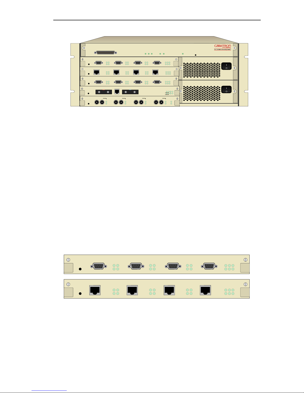
Figure 1-1 ATX Front Panel
1.5 STANDARDS
The physical and electrical characteristics of the Token Ring module
conform to the IEEE 802.5 standard. The protocol for the MAC layer is
specified by the IEEE 802.5 standard while that for the Logical Link
Layer is specified by the IEEE 802.2.
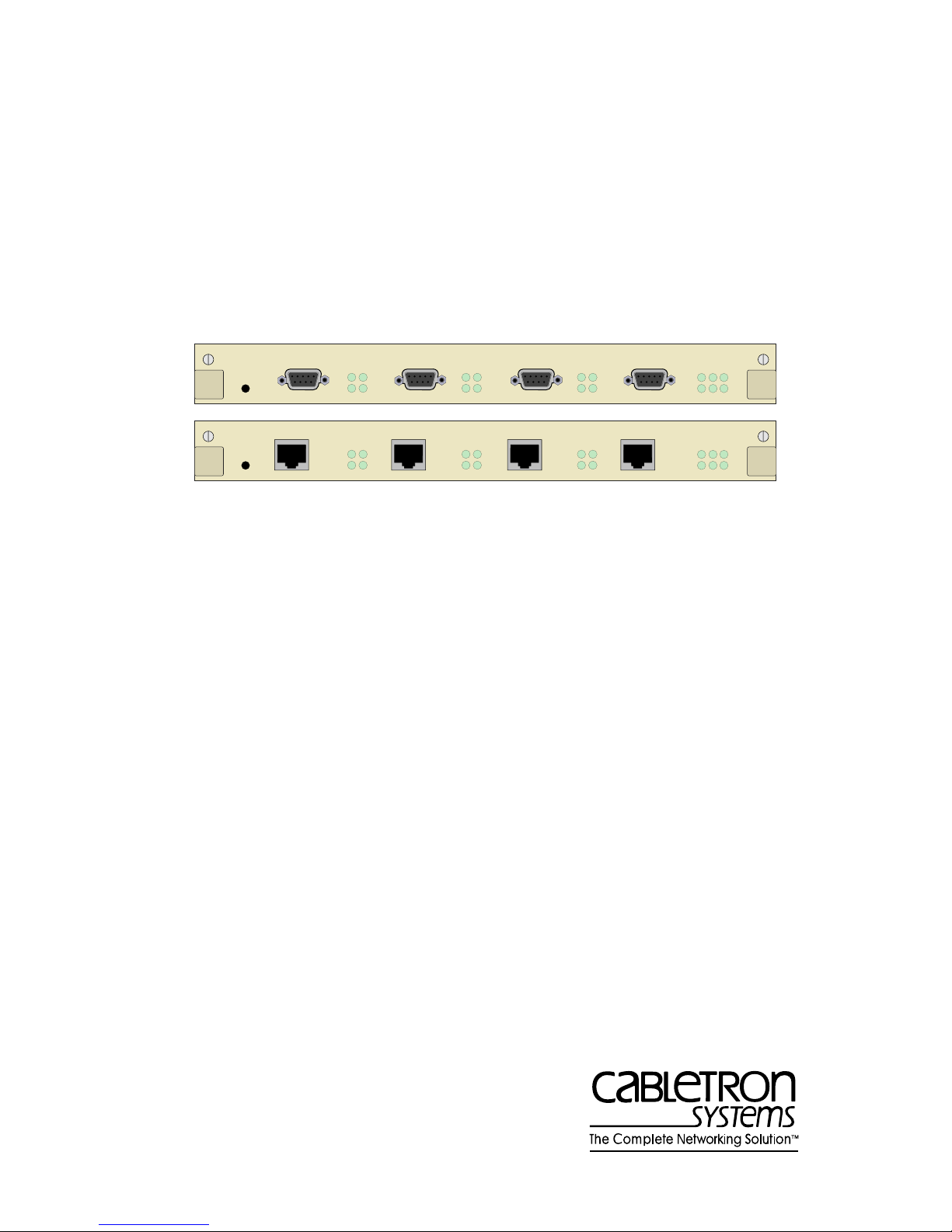
1.6 CONNECTORS
The Token Ring modules are available in versions for either UTP or STP
lobe cabling. The STP version of the four port Token Ring module has
four DB9 connectors; the UTP version has four RJ45 connectors. Power
for the module is provided by the ATX backplane.
QUAD IEEE 802.5 TOKEN RING (STP)
RING 3
RX ST
QUAD IEEE 802.5 TOKEN RING (UTP)
RING 3
RX ST
RING 4
RX ST PROC
RING 4
RX ST PROC
OFFLINE
OFFLINE
RING 1
RX ST
RING 2
RX ST
TX 16 TX 16 TX 16 TX 16 PWR
RING 1
RX ST
RING 2
RX ST
TX 16 TX 16 TX 16 TX 16 PWR
Figure 1-2 3T02-04 and 3T01-04 Front Panels
Token Ring Switch Module User Guide Page 1-5
Page 14

Chapter 1:
Introduction
1.7 LEDs
Each Token Ring module provides 18 green LEDs for troubleshooting
and status monitoring. For each of the four Ring ports there are four LEDs
labeled RX, TX, ST, and 16. Additionally there are two module LEDs
labeled PROC and PWR. The LEDs are described in Chapter 5 of this
manual.
Page 1-6 Token Ring Switch Module User Guide
Page 15

CHAPTER 2
CONNECTING TO THE NETWORK
2.1 INTRODUCTION
Installation of a Token Ring network typically requires more planning and
explicit configuration than does a transparently-bridged Ethernet network.
This chapter provides reference material and instructions that network
administrators can use to configure the Token Ring modules.
For instructions on adding a Token Ring module to the ATX, see
Chapter 6,
Adding/Swapping Modules
2.2 POWER-UP LED SEQUENCE
Power up the ATX and observe the LED sequence. It takes about 1 minute
for the ATX to complete the power-up diagnostics. The ATX begins
system diagnostics on the PPE (topmost module) and then individually on
each installed module progressing from top to bottom.
.
The power-up LED sequence for the Token Ring module not attached to a
network is as follows:
1. All LEDs flash.
2. The POWER and 16 LEDs remain on.
3. After a few seconds the PROC LED comes on.
4. The ST LEDs come on.
5. The RX and TX LEDs flash briefly.
6. The ST and PROC LEDs go off.
7. The PROC LED comes on and the 16 LEDs go off.
8. The TX and RX LEDs flash briefly.
9. The Token Ring module then boots with the PROC and PWR LEDs
on.
10. All other LED activity beyond this point is a function of the
configuration and connection of the ATX.
Token Ring Switch Module User Guide Page 2-1
Page 16

Chapter 2:
Connecting to the Network
2.3 TYPICAL CONFIGURATIONS
Physical connectivity to a Token Ring network is provided by either
shielded twisted pair (STP) or unshielded twisted pair (UTP) cabling that
connects the Token Ring module to a Hub. Each Token Ring switch
module provides only one kind of connector, either four DB9 connectors
for STP cabling or four RJ45 connectors for UTP cabling.
2.4 CONNECTING THE TOKEN RING MODULE
TO A HUB
It is not possible to attach workstations directly to the ATX Token Ring
port. Either an active or a passive Hub must be used. A passive Hub
contains fairly simple electronics (principally relays) which form a
self-healing electrical ring. An active Hub contains more sophisticated
ring-maintenance circuitry and may be manageable.
2.4.1 Unshielded T wisted Pair
When using Unshielded Twisted Pair cabling in a Token Ring
environment, mak e sure that it conforms to the specifications in Table 2-1
(this assumes patch cables that are no longer than 8 feet or 2.4 meters):
Table 2-1 Unshielded Twisted Pair Cabling Specifications
Data Rate Compatibility Cable Type Longest Lobe
4 Mbps
16 Mbps
IBM and IEEE
UTP 802.5
Token Ring
IBM and IEEE
UTP 802.5
Token Ring
EIA/TIA Category 3/4
EIA/TIA Category 5
EIA/TIA Category 3/4
EIA/TIA Category 5
100 m (328 ft.)
125 m (410 ft.)
45 m (147 ft.)
45 m (147 ft.)
a. To assure compatibility with future LANs, the longest lobe should be limited to
100 meters.
a
Page 2-2 Token Ring Switch Module User Guide
Page 17

Connecting the Token Ring Module to a Hub
Refer to the Hub manufacturer’s manual for specific cabling information
for connecting workstations to the Hub.
To connect the Token Ring module to a UTP Hub, attach one end of a
UTP cable to the Token Ring module’s RJ45 connector and connect the
other end with the appropriate connector to any port
except
the Ring In or
Ring Out ports on a UTP Hub. The Ring In/Ring Out ports are used for
interconnecting Hubs. Refer to the example shown in Figure 2-1.
Figure 2-1 Connecting a Token Ring Module to a UTP Hub
2.4.2 Shielded T wisted Pair
When using Shielded Twisted Pair cabling, refer to the following (this
assumes patch cables that are no longer than 8 feet or 2.4 meters):
Table 2-2 Shielded Twisted Pair Cabling Specifications
Data Rate Compatibility Cable Type Longest Lobe
IBM and IEEE
4 Mbps
16 Mbps
802.5 Token
Ring
IBM and IEEE
802.5 Token
Ring
IBM Types 1 240 m (787 ft.)
IBM Types 1 100 m (328 ft.)
a. To assure compatibility with future LANs, the longest lobe should be limited to
100 meters.
a
Token Ring Switch Module User Guide Page 2-3
Page 18

Chapter 2:
Connecting to the Network
To connect to an STP MAU, attach the DB9 end of a Token Ring adapter
cable to the Token Ring module’s DB9 connector. Attach the Media
Interface Connector (MIC), on the other end of the cable, to any port
except
the Ring-In or Ring-Out ports on a STP MAU. The Ring-In/
Ring-Out ports are used for interconnecting MAUs. Refer to the example
shown in Figure 2-2.
QUAD IEEE 802.5 TOKEN RING (STP)
RING 3
RX ST
RING 4
RX ST PROC
OFFLINE
RING 1
RX ST
TX 16 TX 16 TX 16 TX 16 PWR
RING 2
RX ST
RI RO
Figure 2-2 Connecting a Token Ring Module to an STP MAU
Page 2-4 Token Ring Switch Module User Guide
Page 19

CHAPTER 3
CONFIGURING
3.1 INTRODUCTION
You can configure the Token Ring module using the Local Console
Manager (LCM), which allows you to monitor, manage, and configure
your ATX through an out-of-band RS-232 connection. You can also use
any SNMP compliant network management system.
For more details about LCM, see your
the other network management software, refer to the product’s
documentation.
The following attributes are configurable using LCM:
• Speed of the Token Ring network (4 or 16 Mbps)
• Port's IP address for originating and receiving IP packets
• Enabling/disabling a port's Transparent Spanning Tree, Source
Routing or Source Routing Transparent mode
• Protocol translations
Additionally, the following attributes are configurable using network
management software (refer to the network management software
documentation for specific instructions):
• 48-bit unique MAC address
ATX User Guide
. For details about
• Alarm thresholds for hardware errors
• Parameters for diagnostic loopback testing of a port
Filtering normally occurs as part of the Transparent Spanning Tree and
Source Routing algorithms. In addition, configurable criteria may be
established for filtering, to allow greater management control for security
or network congestion reasons. All configured filtering criteria are
Token Ring Switch Module User Guide Page 3-1
Page 20

Chapter 3:
Configuring
maintained in non-volatile memory and are saved across power cycles.
Filtering information is covered in the ATX User Guide.
Once the Token Ring module is installed in the ATX, the ring
NOTE
speed must be configured prior to connecting the module to a
network. The default ring speed is 4 Mbps; the ring speed only
needs to be configured if your network is running at 16 Mbps.
After the ring speed is set, you may connect the module to a network and
then complete the software configuration, or you could complete all the
software configurations and then attach the module to a network.
3.2 CONNECTING THE LCM
Connect the Local Console Manager (LCM) to the ATX. Refer to
Chapter 2, Installation, of the ATX User Guide for specific instructions.
Make sure the ATX is powered on and press the <Return> key twice.
When the ATX> prompt appears LCM is ready to use.
3.3 LCM COMMANDS
Refer to the A TX User Guide for the generic LCM commands. Familiarize
yourself with LCM before configuring the module.
Specific instructions for setting the ring speed, enabling/disabling a port’ s
bridging type, and translations for the Token Ring module follow in this
chapter.
If you are enabling IP routing, you need to assign addresses to the ports
which will be performing routing functions. Refer to the A TX User Guide
for instructions on assigning an IP address.
Page 3-2 Token Ring Switch Module User Guide
Page 21

Setting the Ring Speed
3.4 SETTING THE RING SPEED
Before the Token Ring module can be connected to a network, the ring
speed must be set. Token Ring signaling takes place at either 4 or 16
Mbps. The default setting is for 4 Mbps. All stations on the same ring
must operate at the same speed.
A single station configured to the wrong speed may bring down
!
CAUTION
the entire ring, therefore, the ATX should be configured to the
appropriate speed before physically connecting it to the
network.
Using LCM, at the ATX> prompt, type
ringspeed followed by the port
number and the desired speed. For example, to set port 9 to 16 Mbps type:
ATX> ringspeed 9 16
The LCM displays 16000000 bits/second.
If set to 4 Mbps, LCM displays
4000000 bits/second.
The Token Ring modules include an LED for each Token Ring port that
indicates for which speed the port is configured. If the port is configured
for 16 Mbps, the LED will be on; if configured for 4 Mbps, the LED will
be off. For Token Ring Switch Modules, set each port’s ring speed, if
necessary.
3.5 CONFIGURING THE BRIDGING TYPE
3.5.1 Transparent
The ATX defaults to transparent bridging for all ports. If this is
acceptable, no further configuration is necessary.
Token Ring Switch Module User Guide Page 3-3
Page 22

Chapter 3: Configuring
3.5.2 Source Routing and SRT
Source routing and SR T bridging can be configured from LCM, or from a
generic MIB browser. It is necessary to configure:
• Bridging method for each port
• Segment (ring) number for each port
• Bridge number for the ATX as a whole
A port must be configured for source routing or SRT before configuring
the segment and bridge numbers. Unlike transparent bridging, source
routing and SRT require explicit designation of segment (ring) numbers
and bridge numbers.
3.5.2.1 Bridging Method
To configure bridging from LCM, enter bridge followed by the port
number, and the keyword
sr for source routing or srt for source routing
transparent. For example, to enable IBM source routing on Token Ring
port 9, type:
ATX> bridge 9 sr
To change the port back to transparent bridging, type:
ATX> bridge 9 transparent
3.5.2.2 Segment Number
Segment numbers range from 1 to 4095 and must be unique within the
bridged network. To set the segment number from LCM for either source
routing or source routing transparent, use the
followed by the port number and the desired segment number. For
example, to set the segment number for port 9 to 109, enter:
ATX> srsegment 9 109
srsegment command,
Page 3-4 Token Ring Switch Module User Guide
Page 23

Translation Options
3.5.2.3 Bridge Number
The ATX, unlike some multiport source routing bridges, does not impute
an internal pseudo-ring, and so its bridge number must be unique on each
of the segments to which it is attached. The omission of the pseudo-ring
has the advantage of increasing the allowable network diameter by
consuming one hop per transit instead of two.
Bridge numbers range from 1 to 15 and must be unique between any pair
of segments. To set the bridge number from LCM for either source
routing or source routing transparent, use the
srbridge command
followed by its value. For example, to set the bridge number to 7, enter:
ATX> srbridge 7
3.6 TRANSLATION OPTIONS
The ATX offers unique abilities to bridge between Ethernet and Token
Ring (as well as FDDI), despite protocol differences between the
dissimilar media. The ATX provides a number of options for overcoming
translating problems. The options are specific to the higher-layer protocol
family.
You can set the types of translations that are available for Token Ring
ports. Ports may have a combination of different translation types. The
translation options are:
• ARP - translates incoming and/or outgoing ARP packets
• srArp - translates incoming ARP packets that are source routing
explorer frames
• IPX - translates incoming and outgoing Novell IPX packets
• APPLE - translates incoming and outgoing AppleTalk ELAP, TLAP,
and AARP packets
The types of custom mixed LAN translations that are av ailable, as well as
the translations that have been acti v ated for your Token Ring ports, can be
displayed. (Currently, custom mixed LAN translations may only be
specified for Token Ring ports.) To display this information enter:
Token Ring Switch Module User Guide Page 3-5
Page 24

Chapter 3: Configuring
ATX> translate
To display the translations that have been activated for indicated ports,
enter
translate followed by a Token Ring port range. For example:
ATX> translate 2-4
To display the options that are av ailable for the specified translation type,
enter:
ATX> translate port range translation type
Token Ring ports may have any combination of the different translation
types. To enable the translation type in the manner specified by option for
the indicated ports, enter:
ATX> translate {port range} {translation type} option
To disable all translation types for the indicated ports enter:
ATX> translate {port range} none
3.6.1 ARP T ranslation
The ARP translation options are intended to compensate for any likely
implementation of IP's ARP on 802.5 Token Rings. The possibilities for
option are the following:
• Off – no special ARP translation to be performed
• Bitswap1 – embedded MA C addresses for ARP packets with hardware
type 1 (Ethernet) will be bit swapped (this applies to all ARP packets
received by the port, and to all ARP packets to be transmitted by the
port).
• Bitswap6 – embedded MA C addresses for ARP packets with hardware
type 6 (IEEE 802) will be bit swapped (this applies to all ARP packets
received by the port, and to all ARP packets to be transmitted by the
port).
• Bitswap61 – both type 1 and type 6 ARP packets will be bit swapped.
• Oneto6 – incoming type 6 ARP packets will be changed to type 1 and
outgoing type 1 ARP packets will be changed to type 6, both without
bit swapping.
Page 3-6 Token Ring Switch Module User Guide
Page 25

Translation Options
• Oneto6swap – incoming type 6 ARP packets will be converted to type
1 and outgoing type 1 to type 6, with embedded addresses bit swapped.
3.6.2 Source Routing ARP Translation
The Source Routing ARP translation options specify when bridging IP
ARP packets that are source routing explorer frames, whether the routing
information is to be stripped or propagated. The possibilities for option
are the following:
• Off – no special ARP translation is to be performed.
• PassRif – the pack et is bridged as is, with route disco v ery proceeding
as expected (the passRif option is identical to the off option).
• StripRif – the routing information field is stripped before being
propagated (this option allows non source routing (e.g., Ethernet) IP
hosts to communicate transparently).
• PassBoth – both the original source routed packet and its transparent
equivalent are propagated (this option provides maximum
connectivity at some expense in network traffic).
3.6.3 IPX T ranslation
The IPX translation options specify, when bridging Novell IPX packets,
whether the packets are to be translated to Ethernet-like format. The
possibilities for option are:
• Off – no special IPX translation is to be performed
• On – the default IPX translation of the switch is to be performed (If no
ports have any IPX options, then the default option is ethernet8023.)
• Ethernet8023 – the 802.3 header is to be used without an 802.2 frame
(this also changes the default to Ethernet 8023 framing)
• Ethernet2 – Ethernet 2 framing is to be used, with ether Type 8137
(this changes the default to Ethernet2 framing)
• Ethernet8022 – the LLC header e0, e0, 03 is to be used in conjunction
with the 802.3 header (this also changes the default to ethernet8022
framing)
Token Ring Switch Module User Guide Page 3-7
Page 26

Chapter 3: Configuring
All Token Ring ports that have IPX translation enabled should
NOTE
always use the same option.
To enable the default option for port 5, enter:
ATX> translate 5 ipx on
To change the default to ethernet2, and change the IPX option to
ethernet2 for ports 5 and 6.
ATX> translate 6 ipx ethernet2
To change the default to ethernet8022, and change the IPX option to
ethernet8022 for ports 5, 6, and 7.
ATX> translate 7 ipx ethernet8022
3.6.4 AppleT alk T ranslation
AppleTalk Phase 1 does not exist on Token Ring and so is not a
NOTE
concern here. Also, since the ATX does not have physical
LocalTalk connections, LocalTalk/LLAP is not a concern. Apple
Macintoshes may be attached directly to standard LANs or ma y
employ various LocalTalk-to-Ethernet routers to access LAN
internetworks.
Page 3-8 Token Ring Switch Module User Guide
Page 27

Translation Options
Ethernet AppleTalk (ELAP) differs from Token Ring AppleTalk (TLAP)
in AARP packets and in the use of zone multicast addresses. If so
configured, the ATX will translate AARP packets and will exchange zone
multicast addresses as needed.
On Token Ring, certain AppleTalk packets are transmitted as
NOTE
source routing explorers. If translation is enabled, the ATX will
pass both the original frame and a stripped copy of the frame.
This may double the multicast traffic on the Internet. Given
AppleTalk’s propensity for frequent multicast packets, network
administrators should use this option with care.
The AppleTalk translation options specify when bridging AppleTalk
ELAP, TLAP, and AARP packets, whether the packets are to be translated
to Ethernet-like format. The possibilities for option are:
• Off - perform no translation
• On - translate the packets
To enable AppleTalk translation from LCM, enter
a Token Ring port range,
ATX> translate 4-6 apple on
apple and on. For example:
translate followed by
Token Ring Switch Module User Guide Page 3-9
Page 28

Chapter 3: Configuring
Page 3-10 Token Ring Switch Module User Guide
Page 29

CHAPTER 4
STATISTICS
4.1 DISPLAYING PORT STATUS
Using LCM, you can obtain the status of a specific Token Ring port by
typing
numbers.) A sample display of a Token Ring port status is shown below.
status <port number>. (Type status to display all the ATX port
ATX >status 7
Port 7 (1st port on module 3) Status
Type: 4Mbps 802.5 Token Ring
Bridging: Source Routing Transparent Bridging (segment=0,
bridge=0)
Routing: IP Routing
Enabled/Disabled: Bridging/Routing functions enabled
Spanning Tree: Forwarding
Packets Transmitted: 324
Packets Received: 627
Small Buffers: 65
RxQ Overflows: 37
Ring State: Open
Ring Status: No Problems
The status of a Token Ring port includes the following information:
• Type - whether the ring is operating at 4 or 16 Mbps, and the module
type, i.e., 802.5 Token Ring.
• Bridging - which functions have been enabled for bridging (see the
bridge command).
• Routing - which functions hav e been enabled for routing (see
ipxroute commands in your NMS manual).
and
iproute
• Enabled/Disabled - enabled if it is operational, or disabled if you used
the disable command to disable it. If the port is enabled but not
operational, its status will be broken. (A port could be broken if it is so
badly misconfigured as to be unusable. You might also see a status of
broken if an FDDI or Token Ring port can’t connect to a logical ring,
or if an Ethernet port continually fails as it tries to transmit.). Refer to
your NMS manual for commands.
Token Ring Switch Module User Guide Page 4-1
Page 30

Chapter 4: Statistics
• Spanning T ree - the port's Spanning T ree state. This entry sho ws status
only; it is not selectable. The following states apply to Spanning Tree:
- Blocking - The port is not currently the designated port to the LAN
and is therefore not forwarding any packets. (This means there is
another route to that LAN and, since the Spanning Tree protocol
does not allow simultaneous redundant paths, this port is blocked.
If the other route to that LAN goes down, this port would then
begin forwarding packets.)
- Listening - The port is listening for other bridges on the network
to determine if it should go to the forwarding or blocking state.
- Learning - The port is listening for other bridges on the network
and making a table of addresses from packets that it has receiv ed.
Once the port goes to the forwarding state, it can then use the
address information it has learned.
- Forwarding - The port is the designated port for the LAN and is
forwarding packets and sending out bridge protocol packets.
- Broken - The port is not forwarding packets. Reasons include no
cable connected, no link status, the ring is not operational, or an
NMS has disabled the port.
- Disabled - The port is not configured for Spanning Tree.
• Packets Transmitted - number of packets transmitted from the port.
This entry shows status only; it is not selectable. This includes any
packets that might have experienced transmission errors. (The port’s
statistics are reset whenever the port is started.)
• Pack ets Receiv ed - number of good packets recei ved through the port.
This entry shows status only; it is not selectable. Packets with
reception errors are not included, nor are packets local to that segment
that are hardware filtered.
• Small Buffers - number of buffers currently assigned to the port (see
RX_Q Overflows below). This entry shows status only; it is not
selectable.
Page 4-2 Token Ring Switch Module User Guide
Page 31

Displaying Port Status
• RX_Q Overflows - number of incoming packets dropped by the port
due to a lack of buffers. This entry shows status only; it is not
selectable. After a reboot, the ATX tries to automatically re-allocate
the Small Buffers among the ports so that the total number of RX_Q
Overflows is minimized.
• Ring State - either opened, closed, or ring failure. This entry shows
status only; it is not selectable.
• Ring Status - normally No Problems Detected. This entry sho ws status
only; it is not selectable. If there are ring problems, one of the
following will be displayed:
- Ring Recovery - This could be a normal state, indicating that a
new station has just inserted into the ring and temporarily broken
it. The ring should be back to normal in seconds. If it is not, check
for stuck relays on a passive MAU, DB9 connectors plugged into
the video port, mismatched ring speed (some stations at 4, some at
16), or poor wiring or connections.
- Single Station - The module’s Token Ring port is the only station
it sees on the ring.
- Auto Removal - There is a serious problem with the connection,
which resulted in the Token Ring port removing itself from the
ring. Check the conditions listed under Ring Recovery.
- Lobe Wire Fault - The cable between the ATX and the MAU is
defective causing the loopback test to fail. Therefore, the Token
Ring port isn’t inserted into the ring.
- Soft Error - Historically indicates that an error has occurred. This
can be caused by inserting a new station into the ring. Since this
value represents a historical set, it may not necessarily indicate a
current error condition.
- Hard Error - This frequently occurs when a ne w station is inserted
into the ring; it can be ignored.
- Transmitting Beaconing - As state similar to Ring Recovery.
Follow the guidelines above.
- Signal Loss - The Token Ring port is unable to communicate with
the ring.
Token Ring Switch Module User Guide Page 4-3
Page 32

Chapter 4: Statistics
- Remove Received - The Token Ring port has removed itself from
the ring.
All of the counter values are reset to zeros if the ATX is
NOTE
rebooted or if the module housing that port is halted and
restarted.
4.2 MODULE STATISTICS
Interface-related statistics are maintained for NMS examination in se veral
portions of the management information base (MIB). These include the
“if” portion of MIB II, the bridge MIB[5], the 802.5 MIB, and proprietary
MIB entries. The proprietary MIB port statistics are summarized below:
sifRxPackets - The number of received packets by category. Each of
•
the possible 25 categories is the cross-product of the five destination
addresses and the five forwarding outcomes (see Table 4-1).
Table 4-1 Destination Addresses and Forwarding Outcomes
Destination Address Forwarding Outcome
1. a bridge management unicast
address
2. a bridge management multicast
address
3. a known non-management
address
4. an unknown non-management
unicast address
5. an unknown non-management
multicast address
•
sifRxChar0s - The number of characters in the forwarded received
i. packet forwarded
ii. packet filtered (local traffic)
iii. packet filtered (port blocked)
iv. packet filtered (source restriction)
v. packet filtered (destination
restriction)
packets.
• sifRxChar1s - The number of characters in the filtered received
packets.
Page 4-4 Token Ring Switch Module User Guide
Page 33

Module Statistics
• sifRxSizeErrors - The number of received packets discarded due to
size errors.
• sifRxHwFCSs - The number of received packets discarded due to FCS
errors.
• sifTxPackets - The number of transmitted packets divided into five
categories. The number of packets in each category is encoded as a
series of 4 bytes, which should be conv erted into a 32 bit counter. The
five categories of destination addresses are described in Table 4-1.
sifTxCongests - The number of packets not transmitted due to transmit
•
congestion.
• sifTxStorms - The number of packets not sent due to protection against
a multicast storm.
• sifTxDests - The number of packets not sent due to a destination port
filtering restriction.
• sifTxSizes - The number of packets not sent due to size limitations.
Token Ring Switch Module User Guide Page 4-5
Page 34

Chapter 4: Statistics
Page 4-6 Token Ring Switch Module User Guide
Page 35

CHAPTER 5
DIAGNOSTICS AND TROUBLESHOOTING
5.1 POWER-UP DIAGNOSTICS
5.1.1 Power-up T ests
The power-up diagnostics assure that the ATX and all the installed
modules are operational. During diagnostic mode, the status LEDs are
used differently than during normal operation.
When the ATX is powered-up, it automatically senses the installed boards
and reassigns port numbers starting with the PPE as port 1.
During a normal power-up test, the diagnostics test the entire ATX
starting with the PPE and proceeding slot by slot from the top down. The
normal power-up sequence is described in Chapter 2, Connecting to the
Network.
Token Ring Switch Module User Guide Page 5-1
Page 36

Chapter 5: Diagnostics and Troubleshooting
5.1.2 Power-up Results
After completion of the power-up diagnostic sequence, all status LEDs on
the ATX front panel should be on (lit), indicating that the modules have
passed the power-up tests.
Refer to Table 5-1 for descriptions of the LEDs during normal operation.
Table 5-1 Meaning of LEDs
LED Meaning
RX Token Ring port is receiving data (LED flashes)
ST Ring status of port, on if port is inserted into the ring
PROC Token Ring processor is ready for operation (LED on)
TX Token Ring port is transmitting data (LED flashes)
16
POWER Token Ring module hardware is receiving power (LED on)
If LED is on, then port ring speed is set for 16 Mbps, if not on then
port ring speed is set for 4 Mbps
5.2 OPERATIONAL DIAGNOSTICS
5.2.1 Loopback T ests
Built-in local and remote loopback tests can be used to test individual
ports while the ATX is operational. When in local loopback, a port is
disconnected from its network. The ATX generates loopback packets for
the port, and the port loops the packets back without sending them onto its
network.
During a remote loopback test, the port is in normal operation, sending
and receiving packets to its network. The ATX generates loopback
packets which are sent out of the port to a particular destination device on
the port’ s network. The destination de vice echoes the packet back onto the
network, and the originating port receives the packet.
Page 5-2 Token Ring Switch Module User Guide
Page 37

Troubleshooting
For both types of tests, normal operation is indicated when generated
packets are received back (after looping) without errors. For remote
loopback tests, the ATX creates LLC Type 1 test packets for LANs and
PPP echo-request packets for WANs and UARTs.
Both types of loopback tests can be initiated by the NMS, and test results
are reported to the NMS.
5.2.2 Diagnostic Results
The ATX diagnostic results are indicated in two ways: by observing the
front panel LEDs (which are explained later in this chapter) or by reading
NMS trap messages. Both power-up and loopback diagnostics produce
traps, which are sent to the NMS and may be logged for future reference.
In some cases it may be more conv enient to simply observe the LEDs, b ut
in most cases traps provide more information. There are no LEDs for the
loopback tests—the results of these tests must be observed (i.e., accurate
packet transmission) or read using an NMS (i.e., examine traps).
5.3 TROUBLESHOOTING
5.3.1 If the Module Fails to Power Up
If the Token Ring module fails to power up when the ATX is on and
functioning properly:
1. Check the status of ports using LCM.
2. Reset the Token Ring module and observe the power-up sequence
again.
Token Ring Switch Module User Guide Page 5-3
Page 38

Chapter 5: Diagnostics and Troubleshooting
3. If the sequence is still abnormal:
a. Remove the interface module by unscrewing the two retaining
screws on the module’s front panel. Pull the module out using the
“ears” on the front panel.
b. Carefully but firmly press down on all socketed components.
c. Re-install the module. Make sure the module is properly seated
and tighten the retaining screws.
d. Reset the ATX and observe the power-up sequence.
4. If it is still abnormal, contact Cabletron Systems Technical Support.
5.3.2 Connectivity Problems
If the Token Ring module powers up normally but the workstations are
unable to communicate:
1. Check the LEDs for abnormalities which may help indicate the source
of the problem. (LED behavior during normal operation is explained
earlier in this chapter.)
2. Check the status of the ports using LCM.
3. Make sure the ring speed for all stations on the same ring are set for
the same speed. One station configured for a different speed may
disrupt ring operation.
4. Check for loose connections between the Token Ring module and the
MAU and between the MAU and the workstations. Remember, the
Token Ring ports cannot be connected directly to workstations. Also
refer to the MAU’s documentation for additional information, such as
wrapped or open ports.
Page 5-4 Token Ring Switch Module User Guide
Page 39

CHAPTER 6
ADDING/SWAPPING MODULES
Once you have recei v ed your ATX, you may want to add a new module to
expand your network bandwidth, replace a module with a module of a
different type, or swap a module with another module of the same type. If
you are:
• Adding a module to a previously vacant slot or to a slot that had a
different type of module, refer to the section Adding a Token Ring
Switch Module below, for instructions.
• Replacing a Token Ring module, refer to Section 6.3, Swapping a
Module, for instructions.
Before adding or swapping modules, refer to the latest version of the ATX
Release Notes (provided with your ATX software) for information about
software and hardware version numbers and compatibility.
6.1 UNPACKING THE TOKEN RING SWITCH MODULE
Unpack the module carefully, handling it by the edges only , and inspect it
for possible damage. If any damage is evident, contact Cabletron Systems
Technical Support immediately. Save the original container and antistatic
wrap in case the module needs to be repaired.
6.2 ADDING A TOKEN RING SWITCH MODULE
If the module you are adding is of a different type than the module that
previously occupied that slot, or if the slot was previously vacant, you
have to reboot the ATX so it will recognize the new module.
Token Ring Switch Module User Guide Page 6-1
Page 40

Chapter 6: Adding/Swapping Modules
If the module you are adding has a different number of ports than the
module you are removing, before you can power c ycle the ATX you must:
• Delete all static addresses
• Delete all ARP addresses and IP routing table entries
• Delete all filters
1. Make sure the ATX is powered off.
2. Remove the network connections from the module you are going to
replace.
3. Loosen the screws at each end of the front panel of the interface
module you are going to replace.
4. Remove the installed interface module by pulling gently but firmly on
the ears at the ends of the module's front panel.
5. Gently slide the new module into the plastic guides in the module slot
until it is completely inserted. Push the module firmly into place, as far
as it will go, to fully engage the connectors at the back of the module
with the backplane at the rear of the ATX chassis.
6. Tighten the screws on each side of the Token Ring module front panel.
7. Power on the ATX, and check the module LED power-on sequence as
described in Chapter 2, Connecting to the Network.
8. Make the connections to the network as described in Chapter 2.
Page 6-2 Token Ring Switch Module User Guide
Page 41

Swapping a Module
6.3 SWAPPING A MODULE
When swapping identical modules, it is recommended that you remove
power from the ATX. However, the module you are replacing must be
taken offline first, as described below.
1. Take the module to be replaced offline, either by pressing the
OFFLINE button on the module front panel, or by using the Local
Console Manager
2. Remove power from the ATX.
3. Remove the network connections from the module. Note the ports to
which the network connections attach.
4. Loosen the screws at each end of the front panel of the module to be
replaced.
5. Remove the installed module by pulling gently but firmly on the ears
at the ends of the module's front panel.
offline command.
6. Gently slide the new module into the plastic guides in the module slot
until it is completely inserted. Push the module firmly into place, as far
as it will go, to fully engage the connectors at the back of the module
with the backplane at the rear of the ATX chassis.
7. Tighten the screws on each side of the module’s front panel.
8. If you took the original module offline by pressing the OFFLINE
button, the new Token Ring module will automatically come back on
line when it is inserted in the slot.
9. If you used the LCM offline command to take the original module
offline, you must use the
online command to bring the new module
online.
10. Check the module LED power-on sequence as described in Chapter 2,
Connecting to the Network.
11. Make the connections to the network as described in Chapter 2.
Token Ring Switch Module User Guide Page 6-3
Page 42

Chapter 6: Adding/Swapping Modules
Page 6-4 Token Ring Switch Module User Guide
Page 43

APPENDIX A
TECHNICAL SPECIFICATIONS
Standards Compliance
• IEEE 802.5, 802.2, 802.5m, 802.1(d)
• Compatible with IBM Token-Ring environments
• IBM Source Routing
Protocol T ranslations
• TCP/IP
• IPX
• AppleT alk
Dimensions
Length: 30.99 cm (12.2 in)
Width: 24.13 cm (9.5 in)
Weight: 1.02 Kg (2.25 lb)
Environmental Requirements
Operating temperature 5˚ C to 40˚ C (41˚ F to 104˚ F)
Storage temperature -30˚ C to 90˚ C (-22˚ F to 194˚ F)
Relative humidity 0% to 95%, non-condensing
Token Ring Switch Module User Guide Page A-1
Page 44

Appendix A: Technical Specifications
Connectors
• DB9 for STP
• RJ45 for UTP
LEDs
• Power
• Module status
• Ring speed
• Ring status
• Receive activity
• Transmit activity
Bridging Domains
• Transparent
• Source Routing
• Source Routing Transparent
Certifications
Safety UL 1950, CSA C22.2 950, EN60950, and
IEC 950
Emission FCC Part 15 Class A, EN55022 Class A, and
VCCI Class I
Immunity EN50082-1
Page A-2 Token Ring Switch Module User Guide
Page 45

APPENDIX B
BRIDGING METHODS
B.1 OVERVIEW
Each port of the ATX can be configured for transparent (802.1d) bridging,
IBM source routing bridging, or source routing transparent bridging
(802.5M). Depending on network topology, it may be desirable to include
a mix of these methods within a single ATX.
The choice of bridging methods is determined both by end station
requirements and by other internetworking equipment.
Source routing end stations may use any of the three bridging methods.
Transparent end stations must use either transparent or SRT bridging.
When in doubt, transparent bridging is the easiest to configure and use.
If redundant links are employed along with IBM source routing bridges,
then the attached ATX port should be configured for source routing. This
will enable the mesh of bridges to derive a spanning tree suitable for
spanning tree explorer frames and for multicast packets.
If source routing is desired, and either Ethernet or FDDI is to be used as a
backbone between Token Rings, then the Ethernet or FDDI port should be
configured for SRT bridging. (SRT over Ethernet is not a standard, but is
available for use between multiple ATX chassis in backbone applications.
In this case, the “Ethernet” may actually be a microwave or satellite link
with an Ethernet-like interface.)
A common mixture of bridging modes may occur when Ethernet
segments and Token- Ring segments do not exchange data but share an
FDDI backbone. In this case, the Ethernets may be configured for
transparent bridging, the Token Rings for source routing, and the FDDI
backbone for SRT. (Don't infer from this example that SRT is the sum of
transparent and source routing bridging; it is a distinct third method).
The bridging method is dependent on the configuration of the bridge entry
and exit ports, and the value of the Routing Indicator (RII) bit in the
received frame. The following chart summarizes the interaction between
the bridging method.
Token Ring Switch Module User Guide Page B-1
Page 46

Appendix B: Bridging Methods
Exit Port Configuration
Entry
Port
Config.
SRT 0 spanning tree block spanning tree
SR 0 block block block
TST 0 spanning tree block spanning tree
a. source address is not learned
RII
1 source route source route spanning tree
1 source route block block
1 spanning tree
SRT
(Source
Routing
Transparent)
a
SR
(Source
Routing)
block spanning tree
TST
(Transparent
Spanning
Tree)
a
a
B.2 TRANSPARENT BRIDGING
Transparent or spanning tree bridging requires no initial programming.
After being installed on the network, they “learn” and remember the
location of the attached devices by reading the source addresses of
incoming packets. Then they place the source address and port
information in a lookup table.
When a packet comes into a port, the bridge reads the destination address
and attempts to find the location of the destination node using its lookup
table. If the address is in the table, the bridge simply re-transmits the
packet out of the appropriate port. If the address is not found in the table
the bridge re-transmits the packet out of all the ports except the source
port.
Transparent or spanning tree bridges also usually provide some packet
filtering capabilities. On some networks it is desirable to prevent certain
stations from accessing other segments. The ATX uses this bridging
method.
Page B-2 Token Ring Switch Module User Guide
Page 47

Source Routing Bridging
B.3 SOURCE ROUTING BRIDGING
Source routing bridging (SR) is an alternative to transparent or spanning
tree bridging, and is widely used in Token Ring networks. The ATX
supports source routing bridging on Token Ring LANs, and an
enhancement to source routing called SRT on all LANs.
With source routing bridging, all networked devices participate in the
source routing protocol. Each packet that crosses a bridge specifies the
originator's LAN segment, the particular bridge, and the destination LAN
segment. It may also specify intermediate LAN segments and bridges.
Station A Station CBridge B
Ring
7
data packet
address 43 B 7 data
Figure B-1 Source Routing Example
Ring
43
In the example in Figure B-1, a data packet traveling from station C on
LAN 43 through bridge B to station A on LAN 7 must specify the full
route it is to take. The source station is responsible for specifying the
route, hence the term “source routing.”
Bridges in a source routing network must be configured with the LAN
numbers (normally 1 to 4095) to which it is connected and a bridge
number (normally 1 to 15). The network administrator chooses the
numbers; the LAN numbers must be unique in the source routed network
and the bridge numbers must be unique between each pair of LANs.
Token Ring Switch Module User Guide Page B-3
Page 48

Appendix B: Bridging Methods
Source routing workstations need not be configured with route
information; instead they discover the best route to a destination through
the use of explorer frames. In the Figure B-1 example, station C might
first transmit an empty explorer frame. Bridge B would add 43-B-7 as its
portion of the route, and then transmit the explorer on all other LANs.
When the packet reaches station A, it can reverse the route to send a reply
back to C. When C recei v es the reply, both stations have all of the routing
information needed to converse, with no further explorer frames needed.
Part of the original intent of source routing bridging was to enable LANs
to be richly connected by low-performance, low-cost bridges. As shown
in Figure B-2, source routing allows an end station to choose a
less-congested path through a chain of bridges, where each bridge is
likely to become congested.
Station A
Congested
Alternative Route
Figure B-2 Data Path Using Source Routing Bridging
Station C
In contrast to spanning tree bridging, all bridges and all links are active
with source routing bridging; the least-congested path is chosen at
discovery time. With products like the ATX, such congestion avoidance is
rarely necessary, since the bridge is capable of handling nearly any traffic
load without experiencing congestion.
Page B-4 Token Ring Switch Module User Guide
Page 49

Source Routing Transparent Bridging
B.4 SOURCE ROUTING TRANSPARENT BRIDGING
Source Routing Transparent (SRT) bridging is a method that merges
IBM-style source routing with transparent spanning tree bridging. If a
route is present in a packet, then the bridge uses it; otherwise the bridge
applies transparent learning rules. It represents an attempt by the IEEE
standards committee to standardize source routing and correct some
shortcomings in source routing (notably multicast transmission). IEEE
has defined SRT bridging for Token Rings, and ANSI has incorporated it
into the FDDI standards. The ATX supports SRT bridging on these, as
well as on Ethernet (for Ethernet, there is no such standard; the ATX
provides this as a proprietary backbone service).
Token Ring Switch Module User Guide Page B-5
Page 50

Appendix B: Bridging Methods
Page B-6 Token Ring Switch Module User Guide
Page 51

INDEX
A
Adding modules 6-1
ATX
front panel 1-5
B
Bridging
configuring 3-4
domains A-2
method B-1
source routing B-3
SRT 3-4, B-5
transparent B-2
C
Certifications A-2
Configurations 2-2
Configuring 3-2
Connectors A-2
D
Diagnostics
LED 5-2
loopback tests 5-2
power up 5-1
results 5-3
Dimensions A-1
Document conventions 1-2
E
Environmental requirements A-1
L
LEDs
diagnostic 5-2
M
Module statistics 4-4
P
Port status 4-1
Ports
statistics 4-4
Protocol translations A-1
R
Ring speed, setting 3-3
S
Standards compliance 1-5
Statistics
module 4-4
port 4-4
Status
ports 4-1
STP
cabling specifications 2-3
Swapping a module 6-3
T
Technical Support 1-3
Translation options 3-5
Troubleshooting 5-3
F
Filtering 3-2
H
Help 1-3
Token Ring Switch Module User Guide Index-1
U
Unpacking 6-1
UTP
cabling specifications 2-2
Page 52

Index
Index-2 Token Ring Switch Module User Guide
 Loading...