

Page 1
FDDI DUAL-ATTACHED
INTELLIGENT MODULE
(3F00-01 AND 3F55-01)
USER’S GUIDE
3F00-01
OFFLINE
3F55-01
OFFLINE
FDDI MIC A FDDI MIC B
MULTI-MODE MULTI-MODE
FDDI MIC A FDDI MIC B
SINGLE-MODE SINGLE-MODE
OPTICAL BYPASS
OPTICAL BYPASS
RING A
RING B
RING A
RING B
THRU
THRU
SN
WRAP
SN
WRAP
RX PROC
PWR
TX
RX PROC
PWR
TX
9031876-02
Page 2

Page 3

Only qualified personnel should perform installation
procedures.
NOTICE
Cabletron Systems reserves the right to make changes in specifications and other information
contained in this document without prior notice. The reader should in all cases consult Cabletron
Systems to determine whether any such changes have been made.
The hardware, firmware, or software described in this manual is subject to change without notice.
IN NO EVENT SHALL CABLETRON SYSTEMS BE LIABLE FOR ANY INCIDENTAL,
INDIRECT, SPECIAL, OR CONSEQUENTIAL DAMAGES WHATSOEVER (INCLUDING BUT
NOT LIMITED TO LOST PROFITS) ARISING OUT OF OR RELATED TO THIS MANUAL OR
THE INFORMATION CONTAINED IN IT, EVEN IF CABLETRON SYSTEMS HAS BEEN
ADVISED OF, KNOWN, OR SHOULD HAVE KNOWN, THE POSSIBILITY OF SUCH
DAMAGES.
Copyright 1997 by Cabletron Systems, Inc., P.O. Box 5005, Rochester, NH 03866-5005
All Rights Reserved
Printed in the United States of America
Order Number: 9031876-02 January 1998
Cabletron Systems, SPECTRUM,
Workgroup
Systems, Inc.
All other product names mentioned in this manual may be trademarks or registered trademarks of
their respective companies.
SmartSwitch, FEPIM, FEPIM-TX
and
LANVIEW
are registered trademarks and MMAC/
and
FEPIM-FX
are trademarks of Cabletron
FCC NOTICE
This device complies with Part 15 of the FCC rules. Operation is subject to the following two
conditions: (1) this device may not cause harmful interference, and (2) this device must accept any
interference received, including interference that may cause undesired operation.
NOTE:
device, pursuant to Part 15 of the FCC rules. These limits are designed to provide reasonable
protection against harmful interference when the equipment is operated in a commercial environment.
This equipment uses, generates, and can radiate radio frequency energy and if not installed in
accordance with the operator’s manual, may cause harmful interference to radio communications.
Operation of this equipment in a residential area is likely to cause interference in which case the user
will be required to correct the interference at his own expense.
WARNING:
party responsible for compliance could void the user’s authority to operate the equipment.
This equipment has been tested and found to comply with the limits for a Class A digital
Changes or modifications made to this device which are not expressly approved by the
FDDI Dual-Attached Intelligent Module User’s Guide i
Printed on Recycled Paper
Page 4

Notice
DOC NOTICE
This digital apparatus does not exceed the Class A limits for radio noise emissions from digital
apparatus set out in the Radio Interference Regulations of the Canadian Department of
Communications.
Le présent appareil numérique n’émet pas de bruits radioélectriques dépassant les limites applicables
aux appareils numériques de la class A prescrites dans le Règlement sur le brouillage radioélectrique
édicté par le ministère des Communications du Canada.
VCCI NOTICE
This is a Class A product based on the standard of the Voluntary Control Council for Interference by
Information Technology Equipment (VCCI). If this equipment is used in a domestic environment,
radio disturbance may arise. When such trouble occurs, the user may be required to take corrective
actions.
CABLETRON SYSTEMS, INC. PROGRAM LICENSE AGREEMENT
IMPORTANT:
This document is an agreement between you, the end user, and Cabletron Systems, Inc. (“Cabletron”)
that sets forth your rights and obligations with respect to the Cabletron software program (the
“Program”) contained in this package. The Program may be contained in firmware, chips or other
media. BY UTILIZING THE ENCLOSED PRODUCT, YOU ARE AGREEING TO BECOME
BOUND BY THE TERMS OF THIS AGREEMENT, WHICH INCLUDES THE LICENSE AND
THE LIMITATION OF WARRANTY AND DISCLAIMER OF LIABILITY. IF YOU DO NOT
AGREE TO THE TERMS OF THIS AGREEMENT, PROMPTLY RETURN THE UNUSED
PRODUCT TO THE PLACE OF PURCHASE FOR A FULL REFUND.
Before utilizing this product, carefully read this License Agreement.
ii FDDI Dual-Attached Intelligent Module User’s Guide
Page 5

CABLETRON SOFTWARE PROGRAM LICENSE
Notice
1. LICENSE
package subject to the terms and conditions of this License Agreement.
You may not copy, reproduce or transmit any part of the Program except as permitted by the
Copyright Act of the United States or as authorized in writing by Cabletron.
2. OTHER RESTRICTIONS. You may not reverse engineer, decompile, or disassemble the
Program.
3. APPLICABLE LA W. This License Agreement shall be interpreted and governed under the laws
and in the state and federal courts of New Hampshire. You accept the personal jurisdiction and
venue of the New Hampshire courts.
. You have the right to use only the one (1) copy of the Program provided in this
EXCLUSION OF WARRANTY AND DISCLAIMER OF LIABILITY
1. EXCLUSION OF
writing, Cabletron makes no warranty, expressed or implied, concerning the Program (including
its documentation and media).
CABLETRON DISCLAIMS ALL WARRANTIES, OTHER THAN THOSE SUPPLIED TO
YOU BY CABLETRON IN WRITING, EITHER EXPRESSED OR IMPLIED, INCLUDING
BUT NOT LIMITED TO IMPLIED WARRANTIES OF MERCHANTABILITY AND
FITNESS FOR A PARTICULAR PURPOSE, WITH RESPECT TO THE PROGRAM, THE
ACCOMPANYING WRITTEN MATERIALS, AND ANY A CCOMPANYING HARDWARE.
WARRANTY. Except as may be specifically provided by Cabletron in
2. NO LIABILITY FOR CONSEQUENTIAL DAMAGES. IN NO EVENT SHALL
CABLETRON OR ITS SUPPLIERS BE LIABLE FOR ANY DAMAGES WHATSOEVER
(INCLUDING, WITHOUT LIMITATION, DAMAGES FOR LOSS OF BUSINESS,
PROFITS, BUSINESS INTERRUPTION, LOSS OF BUSINESS INFORMATION, SPECIAL,
INCIDENTAL, CONSEQUENTIAL, OR RELIANCE DAMAGES, OR OTHER LOSS)
ARISING OUT OF THE USE OR INABILITY TO USE THIS CABLETRON PRODUCT,
EVEN IF CABLETRON HAS BEEN ADVISED OF THE POSSIBILITY OF SUCH
DAMAGES. BECAUSE SOME STATES DO NOT ALLOW THE EXCLUSION OR
LIMITATION OF LIABILITY FOR CONSEQUENTIAL OR INCIDENTAL DAMAGES, OR
ON THE DURATION OR LIMITATION OF IMPLIED WARRANTIES, IN SOME
INSTANCES THE ABOVE LIMITATIONS AND EXCLUSIONS MAY NOT APPLY TO
YOU.
UNITED STATES GOVERNMENT RESTRICTED RIGHTS
The enclosed product (a) was developed solely at private expense; (b) contains “restricted computer
software” submitted with restricted rights in accordance with Section 52227-19 (a) through (d) of the
Commercial Computer Software - Restricted Rights Clause and its successors, and (c) in all respects
is proprietary data belonging to Cabletron and/or its suppliers.
For Department of Defense units, the product is licensed with “Restricted Rights” as defined in the
DoD Supplement to the Federal Acquisition Regulations, Section 52.227-7013 (c) (1) (ii) and its
successors, and use, duplication, disclosure by the Government is subject to restrictions as set forth in
subparagraph (c) (1) (ii) of the Rights in Technical Data and Computer Software clause at
252.227-7013. Cabletron Systems, Inc., 35 Industrial Way, Rochester, New Hampshire 03867-0505.
FDDI Dual-Attached Intelligent Module User’s Guide iii
Page 6

Notice
DECLARATION OF CONFORMITY
Application of Council Directive(s):
Manufacturer’s Name:
Manufacturer’ s Address:
European Representative Name:
European Representative Address:
Conformance to Directive(s)/Product Standards:
Equipment Type/Environment:
89/336/EEC
73/23/EEC
Cabletron Systems, Inc.
35 Industrial Way
PO Box 5005
Rochester, NH 03867
Mr. J. Solari
Cabletron Systems Limited
Nexus House, Newbury Business Park
London Road, Newbury
Berkshire RG13 2PZ, England
EC Directive 89/336/EEC
EC Directive 73/23/EEC
EN 55022
EN 50082-1
EN 60950
Networking Equipment, for use in a
Commercial or Light
Environment.
Industrial
We the undersigned, hereby declare, under our sole responsibility, that the equipment packaged
with this notice conforms to the above directives.
Manufacturer Legal Representative in Europe
Mr. Ronald Fotino Mr. J. Solari
___________________________________ ___________________________________
Full Name Full Name
Principal Compliance Engineer Managing Director - E.M.E.A.
___________________________________ ___________________________________
Title Title
Rochester, NH, USA Newbury, Berkshire, England
___________________________________ ___________________________________
Location Location
iv FDDI Dual-Attached Intelligent Module User’s Guide
Page 7

CONTENTS
CHAPTER 1 INTRODUCTION
1.1 Overview......................................................................................1-2
1.2 Standards....................................................................................1-3
1.3 Connectors..................................................................................1-3
1.4 LEDs............................................................................................1-4
1.5 Document Conventions...............................................................1-4
1.6 Related Documentation...............................................................1-5
1.7 Getting Help.................................................................................1-6
CHAPTER 2 CONNECTING TO THE NETWORK
2.1 Configuration Options..................................................................2-1
2.1.1 Dual-attached Station .....................................................2-2
2.1.2 Dual-homed Single-attached Station..............................2-3
2.1.3 Single-attached Station................................................... 2-4
2.1.4 Optical Bypass Switch ....................................................2-5
2.2 LED Power-up Sequence............................................................2-5
2.2.1 3F00-01 LED Sequence .................................................2-6
2.2.2 3F55-01 LED Sequence .................................................2-7
2.3 Keying of Media Interface Connectors ........................................2-8
2.3.1 A and B Keying...............................................................2-9
2.3.2 M and S Keying ............................................................2-10
2.4 Connecting the 3F00-01 or 3F55-01 to the Network.................2-10
2.4.1 Pre-connection Information........................................... 2-10
2.4.2 Connecting Dual-attached Stations ..............................2-11
2.4.3 Connecting Dual-homed Single-attached Stations.......2-12
2.4.4 Connecting Single-attached Stations............................ 2-12
2.4.5 Connecting the Optical Bypass Switch.........................2-13
CHAPTER 3 CONFIGURING THE 3F00-01 AND 3F55-01
3.1 Configuration...............................................................................3-1
3.1.1 SMT Version 6.2.............................................................3-2
3.1.2 SMT Version 7.3.............................................................3-3
FDDI Dual-Attached Intelligent Module User’s Guide v
Page 8

Contents
CHAPTER 4 MONITORING AND MANAGING
THE 3F00-01 AND 3F55-01
4.1 Displaying the Module Status ......................................................4-2
4.2 Statistics.......................................................................................4-4
4.2.1 Module Status and Statistics...........................................4-5
4.2.2 Port Status and Statistics................................................4-5
4.2.2.1 General Port Status and Statistics..................4-5
4.2.2.2 Port Receive Statistics....................................4-6
4.2.2.3 Port Transmit Statistics...................................4-7
4.2.2.4 Port Error Status and Statistics.......................4-7
4.2.3 3F00-01/3F55-01 Port SMT Status.................................4-8
4.2.3.1 SMT Version 6.2.............................................4-8
4.2.3.2 SMT Version 7.3.............................................4-9
4.2.4 3F00-01/3F55-01 Port MAC Status...............................4-11
4.2.4.1 SMT Version 6.2...........................................4-11
4.2.4.2 SMT Version 7.3...........................................4-13
4.2.5 3F00-01/3F55-01 Port PHY Status ...............................4-16
4.2.5.1 SMT Version 6.2...........................................4-16
4.2.5.2 SMT Version 7.3...........................................4-17
4.2.6 3F00-01/3F55-01 PATH Group.....................................4-18
CHAPTER 5 DIAGNOSTICS AND TROUBLESHOOTING
5.1 Power-up Tests............................................................................5-1
5.2 Operational Diagnostics...............................................................5-3
5.2.1 Troubleshooting...............................................................5-3
5.2.2 Connectivity Problems.....................................................5-4
CHAPTER 6 ADDING/SWAPPING MODULES
6.1 Unpacking the Switch Module......................................................6-1
6.2 Adding a 3F00-01 or 3F55-01......................................................6-1
6.3 Swapping a 3F00-01 or 3F55-01.................................................6-2
APPENDIX A TECHNICAL SPECIFICATIONS
A.1 Data Rate.................................................................................... A-1
A.2 Standards Compliance................................................................ A-1
A.3 Certifications ...............................................................................A-1
A.4 Fiber Cable .................................................................................A-1
vi FDDI Dual-Attached Intelligent Module User’s Guide
Page 9

Contents
A.5 Optical .........................................................................................A-2
A.6 Interface.......................................................................................A-2
A.7 Status LEDs.................................................................................A-2
A.8 Connectors..................................................................................A-2
A.9 Max Power Requirements...........................................................A-2
A.10 Physical.......................................................................................A-2
A.11 Environmental..............................................................................A-3
APPENDIX B CABLING INFORMATION
B.1 Cables and Connectors...............................................................B-1
INDEX
FDDI Dual-Attached Intelligent Module User’s Guide vii
Page 10

Contents
viii FDDI Dual-Attached Intelligent Module User’s Guide
Page 11

CHAPTER 1
INTRODUCTION
This manual is for system administrators responsible for configuring,
monitoring, and maintaining the ATX. It should be used with the
User Guide
chapter are described below.
and the
ATX MIB Reference Guide
. The contents of each
ATX
• Chapter 1,
provides an overview of the 3F00-01 and 3F55-01.
• Chapter 2,
attach the module to a network.
• Chapter 3,
software configuration options for the module.
• Chapter 4,
provides information on the statistics and traffic analysis a v ailable for
the module.
• Chapter 5,
problems with the module and how to solve them.
• Chapter 6,
installing a new 3F00-01/3F55-01 and replacing a 3F00-01/3F55-01.
• Appendix A,
about the module.
Introduction
Connecting to the Network
Configuring the 3F00-01 and 3F55-01
Monitoring and Managing the 3F00-01 and 3F55-01
Diagnostics and Troubleshooting
Adding/Swapping Modules
Technical Specifications
, outlines the contents of this manual and
, describes how to physically
, discusses the
, discusses detecting
, gives instructions for
, lists technical information
,
• Appendix B,
FDDI Dual-Attached Intelligent Module User’s Guide Page 1-1
Cabling Information
, provides cable pinouts.
Page 12
Chapter 1:
Introduction
1.1 OVERVIEW
The FDDI 3F00-01 and the 3F55-01 are dual-attached modules that
connect the ATX to a Fiber Distributed Data Interface (FDDI) network.
Multiple 3F55-01s and 3F00-01s can be installed in one ATX.
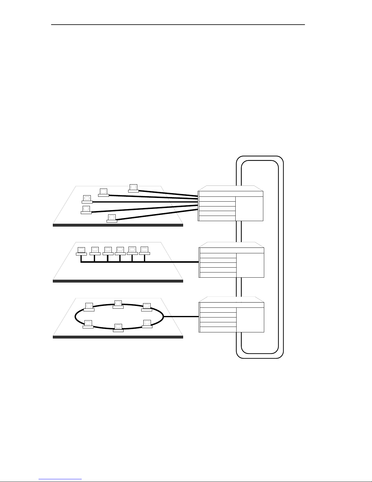
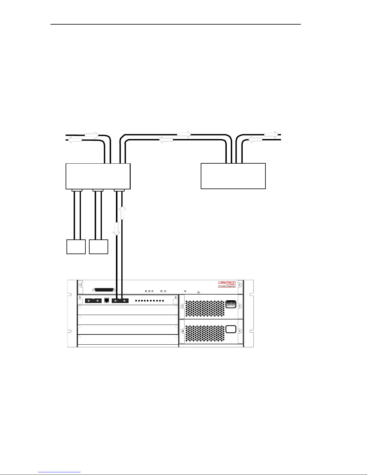
Both modules support a wide range of applications, such as intra-facility
or campus backbones, and client/server configurations. Figure 1-1 shows
a typical campus backbone application, with the ATX linking independent
workgroups on Ethernet and Token-Ring LANs to a high-performance
FDDI backbone.
10BASE-T
Ethernet
10BASE-2
Ethernet
Token-Ring
Token-Ring
Figure 1-1 Typical Network Configuration
ATX
ATX
ATX
FDDI
The 3F00-01 uses standard multimode fiber. The 3F55-01 uses single
mode fiber for extended distance capability. The extended distance
capability for single mode fiber is dependent upon how you want to
allocate your power budget. The 3F00-01 and the 3F55-01 allow the ATX
to be connected to the FDDI ring as a dual-attached station, dual-homed
single-attached station, or single attached station. Both modules support
Page 1-2 FDDI Dual-Attached Intelligent Module User’s Guide
Page 13

Chapter 1:
Introduction
an external Optical Bypass Switch (OBS) that allows full FDDI operation
to continue if the ATX is disabled.
Both FDDI standard station management (SMT) and SNMP are
supported, allowing you to use a v ariety of network management software
to configure your 3F00-01/3F55-01 and monitor your network.
Both the 3F00-01 and 3F55-01 are protected by a built-in temperature
sensor that sends an alarm if the module overheats. Local and remote
loopback tests on the module, and front panel LEDs showing the ring
status, aid in troubleshooting and diagnostics.
1.2 STANDARDS
The 3F00-01 and 3F55-01 comply with the following standards:
• ANSI X3T9.5 (PMD, PHY, MAC, and SMT)
• IEEE 802.1d and 802.1i
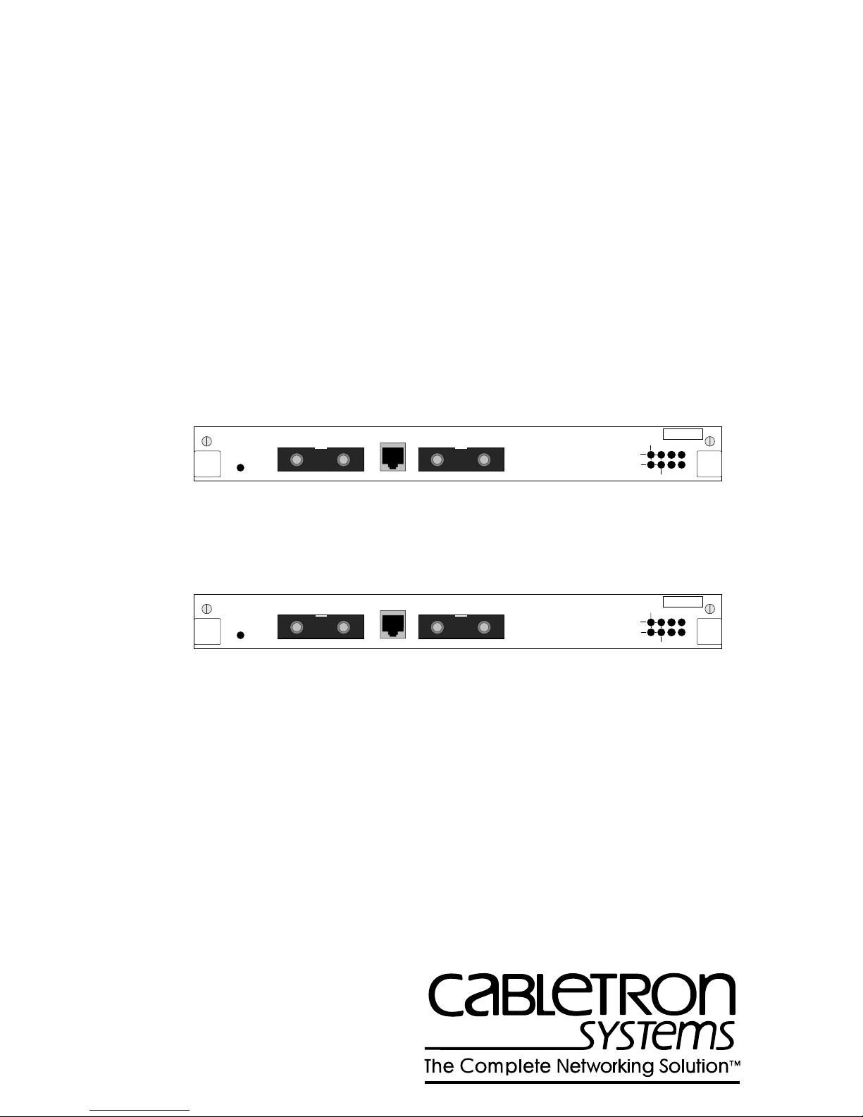
1.3 CONNECTORS
The 3F00-01 and 3F55-01 each have three connectors that are shown in
Figure 1-2 and Figure 1-3:
• Two Media Interface Connector (MIC) receptacles – an A port and a
B port.
• One RJ-11 modular jack, for connecting an optional Optical Bypass
Switch (OBS). (The OBS is not supplied with the 3F00-01 or the
3F55-01.)
RING A
RING B
THRU
SN
WRAP
RX PROC
PWR
TX
3F00-01
OFFLINE
FDDI MIC A FDDI MIC B
MULTI-MODE MULTI-MODE
OPTICAL BYPASS
Figure 1-2 3F00-01 Front Panel
3F55-01
OFFLINE
FDDI MIC A FDDI MIC B
SINGLE-MODE SINGLE-MODE
FDDI Dual-Attached Intelligent Module User’s Guide Page 1-3
OPTICAL BYPASS
Figure 1-3 3F55-01 Front Panel
RING A
RING B
THRU
SN
WRAP
RX PROC
PWR
TX
Page 14

Chapter 1:
Introduction
1.4 LEDS
The 3F00-01 front panel (Figure 1-2) contains 8 green LEDs:
• Processor status (PROC)
• Power OK (PWR)
• Receive activity (RX)
• Transmit activity (TX)
• Thru mode – one per primary and secondary ring (THRU)
• Wrap mode – one per primary and secondary ring (WRAP)
The 3F55-01 front panel (Figure 1-3) contains 8 green LEDs:
• Processor status (PROC)
• Power OK (PWR)
• Receive activity (RX)
• Transmit activity (TX)
• Thru mode – one per primary and secondary ring (WRAP)
• Wrap mode – one per primary and secondary ring (THRU)
1.5 DOCUMENT CONVENTIONS
The following conventions are used in presenting information in this
manual:
LCM commands, prompts, and information displayed by the computer
appear in Courier typeface:
Current Number of Static Addresses: 5
Current Number of Learned Addresses: 133
Number of Defined Filters: 4
Information that you enter appears in Courier bold typeface:
ATX >
Page 1-4 FDDI Dual-Attached Intelligent Module User’s Guide
status
Page 15

Chapter 1:
Introduction
Information that you need to enter with a command is enclosed in angle
brackets < >. For example, you must enter a MAC address to execute the
address matrix
<MAC address>
command:
ATX >
address matrix 00:40:27:04:1a:0f
Field value options appear in bold typeface. F or e xample, a filter type can
be either
Entry
or
Exit
.
Note: A note provides additional information or describes the possible
consequence of a specific action you may perform.
Caution: A caution alerts you that a specific action you may perform
could damage your computer equipment, server communication with your
ATX, or cause data to be lost.
Warning: A warning means you could cause physical harm to yourself.
Follow the guidelines in the manual or on the unit itself when handling
electrical equipment.
1.6 RELATED DOCUMENTATION
You may need to refer to the following documentation when you are using
your ATX:
•
ATX User Guide
for the ATX.
•
ATX MIB Reference Guide
If you need internetworking reference material, you may find the
following books helpful:
•
Interconnections, Bridges and Routers
Wesley
•
Internetworking with TCP/IP: Principles, Protocols, and Architectur e
1992.
(2nd edition), Volumes I and II, Douglas Comer, Prentice Hall
•
The Simple Book, An Introduction to Management of TCP/IP-based
Internets
, Marshall T. Rose, Prentice Hall 1991.
– contains installation and configuration instructions
– contains the SMC Enterprise MIB.
, Radia Perlman, Addison
1991.
FDDI Dual-Attached Intelligent Module User’s Guide Page 1-5
Page 16

Chapter 1:
Introduction
1.7 GETTING HELP
If you need additional support related to this device, or if you have any
questions, comments, or suggestions concerning this manual, contact the
Cabletron Systems Global Call Center:
Phone (603) 332-9400
Internet mail support@ctron.com
FTP ctron.com (134.141.197.25)
Login
Password
BBS (603) 335-3358
Modem setting 8N1: 8 data bits, No parity, 1 stop bit
For additional information about Cabletron Systems or our products,
visit our World Wide Web site:
For technical support, select
anonymous
your email address
http://www.cabletron.com/
Service and Support
.
Before calling the Cabletron Systems Global Call Center, have the
following information ready:
• Your Cabletron Systems service contract number
• A description of the failure
• A description of any action(s) already taken to resolve the problem
(e.g., changing mode switches, rebooting the unit, etc.)
• The serial and revision numbers of all involved Cabletron Systems
products in the network
• A description of your network environment (layout, cable type, etc.)
• Network load and frame size at the time of trouble (if known)
• The device history (i.e., have you returned the device before, is this a
recurring problem, etc.)
• Any previous Return Material Authorization (RMA) numbers
Page 1-6 FDDI Dual-Attached Intelligent Module User’s Guide
Page 17

CHAPTER 2
CONNECTING TO THE NETWORK
The 3F00-01/3F55-01 can be installed in any slot, and more than one can
be installed in your ATX. Refer to the
how to unpack, power up, and check your ATX before continuing with
this chapter.
Instructions for installing or swapping an 3F00-01 or 3F55-01 are
included in Chapter 6,
Adding/Swapping Modules
ATX User Guide
2.1 CONFIGURATION OPTIONS
Both the 3F00-01 and the 3F55-01 permit the ATX to attach to the FDDI
ring as a dual-attached station using either multimode (3F00-01) or single
mode (3F55-01) fiber respectively. They both can also be configured with
an optional Optical Bypass Switch.
for instructions on
.
FDDI Dual-Attached Intelligent Module User’s Guide Page 2-1
Page 18
Chapter 2:
Connecting to the Network
2.1.1 Dual-attached Station
A dual-attached station (DAS) is connected to both the primary and
secondary FDDI rings. This is the preferred configuration, since it
provides the full benefits of dual-ring operation, allowing the network to
continue to operate if a station or cable fails.
Figure 2-1 shows the ATX, with a 3F00-01 installed, connected as a DAS
to two other DASs in an FDDI network. (A and B indicate A port and B
port.) When D AS de vices are connected on an FDDI ring, A ports must be
connected to B ports, and B ports must be connected to A ports.
DAS
B
ABA
AB
FastNET ATX
FDDI MIC A FDDI MIC BOPTICAL BYPASS
NMS PORT
ACT
THRU
RING A RING B
POWER STATUS
ENGINE STATUS
TURBO STATUS
SUPPLY A
SUPPLY B
1.6 Gbps
POWER
POWER
ACT
RX
STATUS
WRAP
WRAP
TX
THRU
RESET
DAS
ATX
PACKET PROCESSING ENGINE
Figure 2-1 Dual-attached Configuration
Page 2-2 FDDI Dual-Attached Intelligent Module User’s Guide
Page 19
Chapter 2: Connecting to the Network
2.1.2 Dual-homed Single-attached Station
Dual-homing is a method of connecting concentrators and stations that
permits an alternate or backup path to the dual ring in case the primary
connection fails.
The connection is normally made via dual-attached concentrators (DACs)
which are connected to both the primary and secondary FDDI rings.
Other FDDI stations or concentrators are connected to the DAC master
(M) ports.
Figure 2-2 shows the ATX, with a 3F00-01 installed, connected to the
master ports of two DACs.
Network
M
DAC 2
M
SAS SAS
M
DAC 1
M
M
SAS SAS
M
Port A Port B
FastNET ATX
NMS PORT
FDDI MIC A FDDI MIC BOPTICAL BYPASS
ACT
THRU
RING A RING B
ATX
POWER STATUS
ENGINE STATUS
TURBO STATUS
SUPPLY A
SUPPLY B
1.6 Gbps
RESET
POWER
POWER
ACT
RX
STATUS
WRAP
WRAP
TX
THRU
PACKET PROCESSING ENGINE
Figure 2-2 Dual-homed Single-attached Configuration
In this configuration, the ATX accesses the FDDI ring through port B and
DAC 2. FDDI standards for D ASs such as the ATX state that if the B port
cannot be used, the device will automatically use its A port. Therefore, if
DAC 2 fails, the ATX is still connected to the ring through port A
(DAC 1).
FDDI Dual-Attached Intelligent Module User’s Guide Page 2-3
Page 20
Chapter 2: Connecting to the Network
2.1.3 Single-attached Station
A single-attached station (SAS) is an FDDI station that uses only one
connection (an S port) for connection to the FDDI ring.
Figure 2-3 shows the ATX, with a 3F00-01 installed, configured as an
SAS, connected to a master port of a dual-attached concentrator (DAC)
on the main FDDI ring.
Network
DAC
M
M
SAS SAS
FastNET ATX
FDDI MIC A FDDI MIC BOPTICAL BYPASS
NMS PORT
M
Port B
ACT
WRAP
THRU
RING A RING B
ACT
POWER STATUS
ENGINE STATUS
WRAP
THRU
TURBO STATUS
POWER
DAS
ATX
SUPPLY A
SUPPLY B
POWER
RX
STATUS
TX
1.6 Gbps
RESET
PACKET PROCESSING ENGINE
Figure 2-3 Single-attached Configuration
Page 2-4 FDDI Dual-Attached Intelligent Module User’s Guide
Page 21
Chapter 2: Connecting to the Network
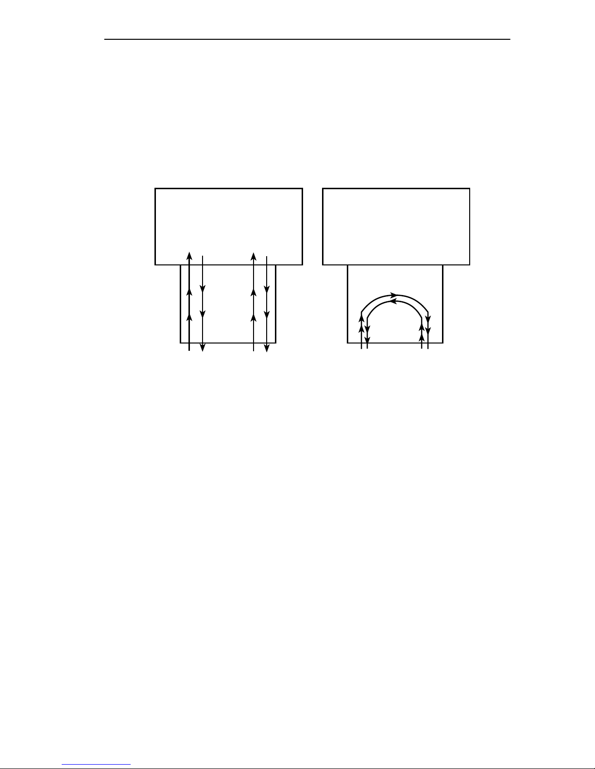
2.1.4 Optical Bypass Switch
An Optical Bypass Switch (OBS) may be used to provide added
protection when the ATX is configured as a DAS. If an OBS is connected
to the 3F00-01 or 3F55-01, and a failure occurs at the ATX, the OBS
automatically isolates the ATX from the rest of the network by
reconfiguring the FDDI dual rings as shown in Figure 2-4.
ATX
3F00-01
OBS
Through Mode
(Normal)
Figure 2-4 Optical Bypass Switch Operation
ATX
3F00-01
OBS
Bypass Mode
This avoids ring “wrapping” (automatic reconfiguration to isolate a f ault)
and ring re-initialization. In addition, an OBS makes it possible to
disconnect the ATX from the network without disrupting the FDDI rings.
2.2 LED POWER-UP SEQUENCE
Before connecting the 3F00-01 or 3F55-01 to the network, power on the
ATX and observe the automatic power-up diagnostics sequence of the
front panel LEDs to check for proper operation. Refer to the ATX User
Guide for instructions on how to power up the ATX.
Each of the modules in the ATX is tested in order, (from top to bottom of
the unit). The power-up sequence takes between 1 and 2 minutes,
depending on the ATX configuration.
FDDI Dual-Attached Intelligent Module User’s Guide Page 2-5
Page 22

Chapter 2: Connecting to the Network
2.2.1 3F00-01 LED Sequence
Figure 2-5 shows the positions of the LEDs on the 3F00-01 front panel.
RING A
RING B
THRU
SN
WRAP
RX PROC
PWR
TX
3F00-01
OFFLINE
FDDI MIC A FDDI MIC B
MULTI-MODE MULTI-MODE
OPTICAL BYPASS
Figure 2-5 3F00-01 LEDs
The LED power-up sequence for the 3F00-01 is as follows:
1. All LEDs light briefly and turn off, except for the PWR LED, which
remains on.
2. The STATUS LED lights while power-up diagnostics are being run on
the 3F00-01.
3. The TX and RX LEDs flash.
4. The STATUS LED goes off while diagnostics are running on the other
modules in the ATX.
5. The STATUS LED lights again when the 3F00-01 software initializes
and remains on.
6. The RING A and RING B RX, TX, THRU, and WRAP LEDs remain
off until the module is connected to the network.
Note: RING A refers to the primary FDDI ring, and RING B to the
secondary FDDI ring. These LEDs do NOT correspond to FDDI MIC A
and FDDI MIC B.
Page 2-6 FDDI Dual-Attached Intelligent Module User’s Guide
Page 23

Chapter 2: Connecting to the Network
2.2.2 3F55-01 LED Sequence
Figure 2-6 shows the positions of the LEDs on the 3F55-01 front panel.
RING A
RING B
THRU
SN
WRAP
RX PROC
PWR
TX
3F55-01
OFFLINE
FDDI MIC A FDDI MIC B
SINGLE-MODE SINGLE-MODE
OPTICAL BYPASS
Figure 2-6 3F55-01 LEDs
The LED power-up sequence for the 3F55-01 is as follows:
1. All LEDs light briefly and turn off, except for the PWR LED, which
remains on.
2. The PROC LED lights while power-up diagnostics are being run on
the 3F55-01.
3. The WRAP LED for Ring A lights briefly.
4. The TX and RX LEDs flash.
5. The PROC LED lights again when the 3F55-01 software initializes
and remains on.
6. The RING A and RING B RX, TX, THRU, and WRAP LEDs remain
off until the module is connected to the network.
Note: RING A refers to the primary FDDI ring, and RING B to the
secondary FDDI ring. These LEDs do NOT correspond to FDDI MIC A
and FDDI MIC B.
FDDI Dual-Attached Intelligent Module User’s Guide Page 2-7
Page 24

Chapter 2: Connecting to the Network
2.3 KEYING OF MEDIA INTERFACE CONNECTORS
Optical fiber connections are made using a Media Interface Connector
(MIC). A MIC consists of two parts:
• The MIC plug, which terminates the optical fiber cable
• The MIC receptacle, which is on the FDDI node or station
To ensure that the MIC plugs and MIC port receptacles are correctly
mated, FDDI standards state that different types of MIC plugs and
receptacles must be keyed as one of the following:
• A (primary in/secondary out)
• B (secondary in/primary out)
• M (master)
• S (slave)
Matching slots are used to identify the MIC plugs and receptacles of the
same type. The MIC key slot must be the correct type for the MIC
receptacle (A, B, M, or S) and must be properly aligned, or you will not
be able to connect the MIC.
The key slot may be permanently molded into the MIC, although many
vendors supply one MIC that can be alternately keyed as an A, B, M, or S
connector. Several MIC vendors provide an attached dust cover that fits
over the end of the MIC plug and contains three small plastic pieces
which may be fitted into the MIC to provide the appropriate keying.
The small movable pieces used to k ey MIC connectors are usually marked
(A, B, M, or S) and are often color coded (usually: red=MIC A, blue or
yellow = MIC B). However, since color coding is not specified in the
FDDI standards, there is no standard color coding scheme.
Page 2-8 FDDI Dual-Attached Intelligent Module User’s Guide
Page 25

Chapter 2: Connecting to the Network
2.3.1 A and B Keying
To install the ATX as a DAS, the preferred configuration, a MIC A and
MIC B are required.
Figure 2-7 shows the keying scheme used to differentiate A and B MICs,
which are identified on the 3F00-01 and 3F55-01 front panel as FDDI
MIC A and FDDI MIC B respectively.
CenterlineCenterline
FDDI MIC B
FDDI MIC A
Centerline
B Keyed MIC plug
Centerline
A Keyed MIC plug
and Receptacle
Figure 2-7 MIC A and MIC B Keying
Key Slot
and Receptacle
Looking into the open end of the receptacle, an A key slot is to the left of
the horizontal center of the MIC and a B key slot is to the right of the MIC
center. The arrows indicate how the plug mates to the receptacle.
Note: If you are making a fiber cable assembly to connect FDDI DAS
devices, the MIC plug on one end must be keyed as a MIC A, and the MIC
plug on the other end must be keyed as a MIC B. This will help ensure
that devices are correctly connected. Also, FDDI terminations should
always be labeled for connection to port A or port B.
FDDI Dual-Attached Intelligent Module User’s Guide Page 2-9
Page 26

Chapter 2: Connecting to the Network
2.3.2 M and S Keying
MICs on concentrators are keyed as type M MICs to connect to a master
port (for the attachment) of stations or other concentrators, and type S
MICs to connect to a slave port (for attachment to the FDDI network).
For M port connections the MIC key slot runs along the center of the
connector.
2.4 CONNECTING THE 3F00-01 OR 3F55-01 TO THE
NETWORK
Caution: Power-off the ATX before connecting the 3F00-01 or 3F55-01
to the network. Failure to disconnect power will result in damage to the
module. The steps for connecting a 3F00-01 or 3F55-01 to the network
are the same.
The 3F00-01 and 3F55-01 connect the ATX to the FDDI network as a
dual-attached station, dual-homed single-attached station, or
single-attached station. Use the appropriate 3F00-01 or 3F55-01; either
the multimode version or single mode version, depending on the type of
fiber used for the network.
2.4.1 Pre-connection Information
Check that MICs are correctly keyed as A and B MICs for connecting
DAS ports.
If MICs are keyed incorrectly, the FDDI network may continue to
function, but the incorrectly connected station will not function. The dual
ring will “twist around,” bypassing the faulty connection. The ring
configuration LED on the 3F00-01 or 3F55-01 (either the THRU or
WRAP LED) will blink.
Before connecting the FDDI cable, inspect the MIC plug and receptacle
contact points to make sure they are clean. (To protect fiber ends from
dust or other contamination, always keep the open ends of unused MIC
plugs and receptacles covered with a dust cover.)
Caution: Only properly trained personnel should attempt to fabricate an
FDDI cable assembly or polish fiber cable terminations.
Page 2-10 FDDI Dual-Attached Intelligent Module User’s Guide
Page 27

Chapter 2: Connecting to the Network
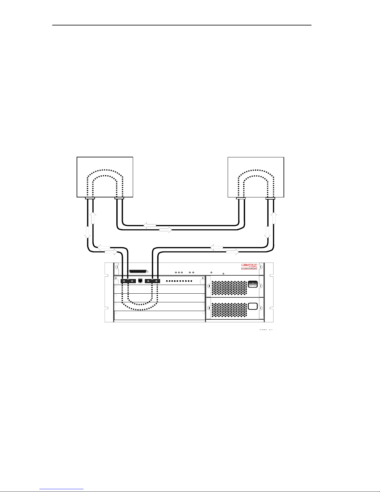
2.4.2 Connecting Dual-attached Stations
The cable assembly consists of a fiber cable (either multimode or single
mode, depending on the type of module you are using) with a MIC A plug
on one end and a MIC B plug on the other end. Two cable assemblies are
required for each ATX that you are connecting.
Note: Remember, when DASs are connected on an FDDI ring, A ports
(MIC A) must be connected to B Ports (MIC B), and B ports must be
connected to A ports.
1. Attach the MIC A plug on the end of one cable assembly to the
receptacle labeled “FDDI MIC A” on the module front panel
(Figure 2-8).
2. Attach the MIC B plug on the other end to the MIC B receptacle on the
first DAS.
3. Attach the MIC B plug on the end of the second cable assembly to the
receptacle labeled “FDDI MIC B” on the module front panel
(Figure 2-8).
4. Attach the MIC A plug on the other end of the second cable to the MIC
A receptacle on the second DAS.
5. Check the LEDs. In this configuration the RING A RX, TX and THRU
LEDs will be on.
3F00-01 Front Panel
FDDI MIC A
MIC A Receptacle
FDDI MIC B
MIC B Receptacle
MIC A Plug
FDDI Dual-Attached Intelligent Module User’s Guide Page 2-11
Lock/Release
Latch
FDDI Cables
Figure 2-8 3F00-01 MIC Connections
MIC B Plug
Page 28

Chapter 2: Connecting to the Network
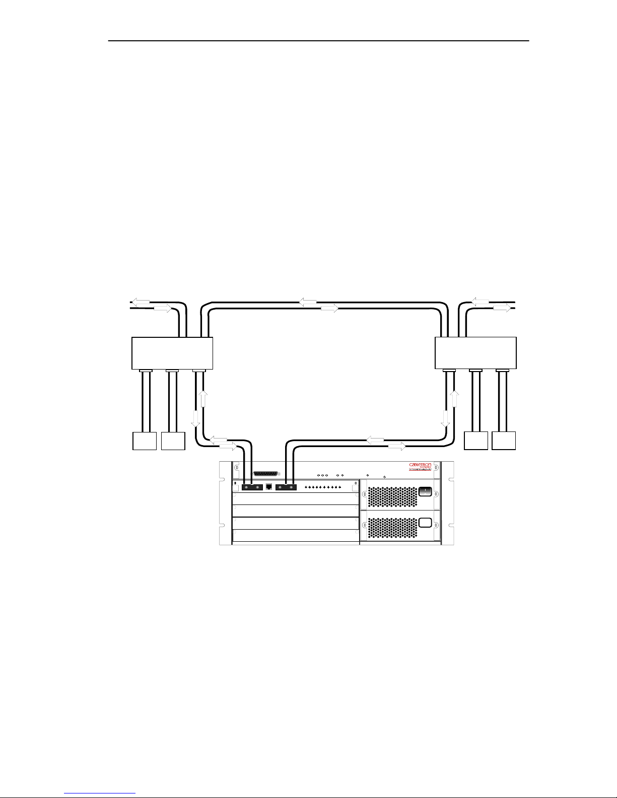
2.4.3 Connecting Dual-homed Single-attached Stations
Two cable assemblies are required for each ATX. One consists of a fiber
cable with a MIC A plug on one end and a MIC M plug on the other end,
and the second consists of a fiber cable with a MIC B plug on one end and
a MIC M plug on the other end.
1. Attach the MIC A plug on the end of the first cable assembly to the
receptacle labeled “FDDI MIC A” on the module front panel
(Figure 2-8).
2. Attach the MIC M plug on the other end of the first cable to the master
port MIC M receptacle on the first DAC.
3. Attach the MIC B plug on the end of the second cable assembly to the
receptacle labeled “FDDI MIC B” on the module front panel
(Figure 2-8).
4. Attach the MIC M plug on the other end of the second cable to the
master port MIC M receptacle on the second DAC.
5. Check the LEDs. In this configuration the RING B RX, TX and
WRAP LEDs will be on.
2.4.4 Connecting Single-attached Stations
The cable assembly consists of one fiber cable with a MIC B plug on one
end and a MIC M plug on the other end.
Warning: When you are using a single-mode cable, do not look at the
end of the cable. The single-mode cable uses a laser, which could cause
damage to your eye if you look directly into it.
1. Attach the MIC B plug on one end of the cable assembly to the
receptacle labeled “FDDI MIC B” on the module front panel
(Figure 2-8).
2. Attach the MIC M plug on the other end to the master port MIC M
receptacle on the DAC.
3. Check the LEDs. In this configuration the RING B RX, TX and
WRAP LEDs will be on.
Page 2-12 FDDI Dual-Attached Intelligent Module User’s Guide
Page 29

Chapter 2: Connecting to the Network
You can use a MIC A plug and the FDDI MIC A receptacle instead of
MIC B, in which case the equivalent RING A LEDs will be on.
2.4.5 Connecting the Optical Bypass Switch
The OBS has three built-in cables with MIC A and MIC B plugs and a
male RJ-11 connector for connecting to the 3F00-01 or 3F55-01. It also
contains MIC A and MIC B receptacles for connecting to the ring.
Figure 2-9 shows the OBS connectors.
You also need two cable assemblies consisting of a fiber cable appropriate
to the type of cabling you are using (either multimode or single mode)
with a MIC A plug on one end and a MIC B plug on the other end to
connect the OBS to the ring.
3F00-01 Front Panel
MIC A
MIC B
Optical
Bypass
Switch
Figure 2-9 Connecting the Optical Bypass Switch
RJ11 Connector
MIC A
MIC B
ATX
1. Attach the MIC A and MIC B plugs on the OBS to the receptacles
labeled “FDDI MIC A” and “FDDI MIC B” respectively on the
module front panel.
2. Plug the male RJ-11 connector on the OBS into the female RJ-11
connector on the module front panel.
3. Attach the MIC A plug on the end of the first cable assembly to the
MIC A receptacle on the OBS (Figure 2-9).
FDDI Dual-Attached Intelligent Module User’s Guide Page 2-13
Page 30

Chapter 2: Connecting to the Network
4. Attach the MIC B plug on the other end of the first cable to the MIC B
receptacle on the first DAS.
5. Attach the MIC B plug on the end of the second cable assembly to the
MIC B receptacle on the OBS (Figure 2-9).
6. Attach the MIC A plug on the other end of the second cable to the MIC
A receptacle on the second DAS.
7. Check the LEDs. In this configuration the RING A RX, TX and THRU
LEDs will be on.
Page 2-14 FDDI Dual-Attached Intelligent Module User’s Guide
Page 31

CHAPTER 3
CONFIGURING THE 3F00-01 AND 3F55-01
You can configure your 3F00-01 and 3F55-01 using the following tools:
• Local Console Manager (LCM), an application that allows you to
monitor, manage, and configure your ATX through an out-of-band
RS-232 connection.
• Remote Console Manager, a remote standalone configuration
application
• EliteView/UX, an SNMP-based network management system
• EliteView/OV, an SNMP-based network management software
module for HP’s OpenView
• EliteView/NV, an SNMP-based network management software
module for IBM’s NetView/6000 network management systems
• Any SNMP-based network management system
For more details about LCM, see your ATX User Guide. For details about
the other network management software, refer to the product’s
documentation.
3.1 CONFIGURATION
Refer to the ATX User Guide for the LCM configuration commands
common to all I/O modules. Configuration information particular to the
3F00-01 and 3F55-01 is described below. Version 2.4 of the ATX system
software supports SMT version 7.3. Versions of ATX system software
prior to 2.4 support SMT version 6.2.
FDDI Dual-Attached Intelligent Module User’s Guide Page 3-1
Page 32

Chapter 3: Configuring the 3F00-01 and 3F55-01
3.1.1 SMT Version 6.2
Some of the SMT version 6.2 MIB variables (snmpFddiSMT 2) have had
their access types extended from Read-Only to Read-Write. These
variables can be written to, using a Network Management Station (NMS).
The variables with extended access include:
snmpFddiSMTStationId – The port’s unique eight byte SMT station
•
identifier (corresponds to ANSI
bytes to zero will cause the unit to automatically use the port’s MAC
address in the lower six bytes.
snmpFddiMACTMax – The MA C’s value for T_Max (corresponds to ANSI
•
fddiMAC 53). Possible values range from 32 to 2,097,120.
•
snmpFddiMACTvxValue – The MAC’s value for Tvx (corresponds to
ANSI
fddiMAC 54). Possible values range from 255 to 65,025.
fddiSMT 11). Setting the lower six
•
snmpFddiMACFrameCts – The MAC’s Frame_Ct (corresponds to ANSI
fddiMAC 71). Any attempt to write this parameter will cause the MAC’ s
Frame_Ct, Error_Ct, and Lost_Ct to be zeroed.
•
snmpFddiMACErrorCts – The MAC’s Error_ Ct (corresponds to ANSI
fddiMAC 81). Any attempt to write this parameter will cause the MAC’ s
Frame_Ct, Error_Ct, and Lost_Ct to be zeroed.
•
snmpFddiMACFrameErrorThreshold – Value for the
fddiMACFrameErrorThreshold variable (corresponds to ANSI fddiMAC
95
).
Variables in the SMC enterprise MIB can be set to specify under what
conditions traps should be sent to an NMS. (Refer to the ATX MIB
Reference Guide for more detailed information.) Those variables include:
• sfddiSmtConditions – SMT conditions which should be reported to
the NMS via SNMP traps.
• sfddiSrfConditions – SRF conditions which should be reported for
the NMS via SNMP traps.
In the SMC enterprise MIB, you can set a variable to connect to port B:
•
sfddiThruB – Whether to connect to the FDDI port B (not applicable
for single-attached stations).
Page 3-2 FDDI Dual-Attached Intelligent Module User’s Guide
Page 33

Chapter 3: Configuring the 3F00-01 and 3F55-01
3.1.2 SMT Version 7.3
Some of the SMT version 7.3 MIB variables (fddimibSMT 2) have had
their access types extended from Read-Only to Read-Write. These
variables can be written to, using an NMS. The variables with extended
access include:
fddimibSMTStationId – The port’s unique eight byte SMT station
•
identifier (corresponds to ANSI
bytes to zero will cause the unit to automatically use the port’s MAC
address in the lower six bytes.
fddimibMACFramesCts – A count of the number of frames received by
•
this MAC (corresponds to ANSI {fddiMAC 71}, refer to ANSI MAC
7.5.1). Any attempt to write this parameter will cause the MAC’s
Frame_Ct, Copied_Ct, Transmit_Ct, Error_Ct, and Lost_Ct to be
zeroed.
fddiSMT 11). Setting the lower six
• fddimibMACCopiedCts – A count that should, as closely as possible,
match the number of frames addressed to (A bit set) and successfully
copied into the station’s receive buffers (C bit set) by this MAC
(corresponds to ANSI {fddiMAC 72}, refer to ANSI MA C 7.5). Note
that this count does not include MAC frames. An y attempt to write this
parameter will cause the MAC’s
Error_Ct, and Lost_Ct to be zeroed.
•
fddimibMACTransmitCts – A count that should, as closely as possible,
Frame_Ct, Copied_Ct, Transmit_Ct,
match the number of frames transmitted by this MAC (corresponds to
ANSI {fddiMAC 73}, refer to ANSI MAC 7.5). Note that this count
does not include MAC frames. Any attempt to write this parameter will
cause the MAC’s
Lost_Ct to be zeroed.
•
fddimibMACErrorCts – A count of the number of frames that were
Frame_Ct, Copied_Ct, Transmit_Ct, Error_Ct, and
detected in error by this MAC that had not been detected in error by
another MAC (corresponds to ANSI {fddiMAC 81}, refer to ANSI
MAC 7.5.2). Any attempt to write this parameter will cause the MA C’ s
Frame_Ct, Copied_Ct, Transmit_Ct, Error_Ct, and Lost_Ct to be
zeroed.
FDDI Dual-Attached Intelligent Module User’s Guide Page 3-3
Page 34

Chapter 3: Configuring the 3F00-01 and 3F55-01
• fddimibMACLostCts – A count of the number of instances that this
MAC detected a format error during frame reception such that the
frame was stripped (corresponds to ANSI {fddiMAC 82}, refer to
ANSI MAC 7.5.3). Any attempt to write this parameter will cause the
MAC’s
Frame_Ct, Copied_Ct, Transmit_Ct, Error_Ct, and Lost_Ct to
be zeroed.
Some of the SMT version 7.3 MIB variables (fddimibSMT 2) have had
their access types restricted from Read-Write to Read-Only . The variables
with restricted access include:
fddimibSMTConfigPolicy – A value that indicates the configuration
•
policies currently desired in a node (corresponds to ANSI {fddiSMT
26}). This is always 0.
fddimibMACRequestedPaths – List of permitted paths which specifies
•
the path(s) into which the MAC may be inserted (corresponds to ANSI
{fddiMAC 32}, refer to ANSI SMT 9.7). Only default setting as
defined in SMT 9.7 is supported.
fddimibPORTConnectionPolicies – A value representing the port’s
•
connection policies desired in the node (corresponds to ‘none’, the
second octet to ‘tree’, and the third octet to ‘peer’.
Variables in the SMC enterprise MIB can be set to specify under what
conditions traps should be sent to an NMS. (Refer to the ATX MIB
Reference Guide for more detailed information.) Those variables include:
sfddiSmtConditions – SMT conditions which should be reported to
•
the NMS via SNMP traps.
• sfddiSrfConditions – SRF conditions which should be reported for
the NMS via SNMP traps.
In the SMC enterprise MIB, you can set a variable to connect to port B:
•
sfddiThruB – Whether to connect to the FDDI port B (not applicable
for single-attached stations).
Page 3-4 FDDI Dual-Attached Intelligent Module User’s Guide
Page 35

CHAPTER 4
MONITORING AND MANAGING
THE 3F00-01 AND 3F55-01
You can monitor your 3F00-01 and 3F55-01 using the following network
management software:
• Local Console Manager (LCM), an application that allows you to
monitor, manage, and configure your ATX through an out-of-band
RS-232 connection.
• Remote Console Manager, a remote standalone configuration
application
• EliteView/UX, an SNMP-based network management system
• EliteView/OV, an SNMP-based network management software
module for HP’s OpenView
• EliteView/NV, an SNMP-based network management software
module for IBM’s NetView/6000 network management systems
• Any SNMP-based network management system
This chapter describes some basic monitoring functions you can perform
using LCM, and additional information you can access using the network
management software listed above.
For more details about LCM, refer to the ATX User Guide. For details
about the other network management software, refer to the product’s
documentation.
FDDI Dual-Attached Intelligent Module User’s Guide Page 4-1
Page 36

Chapter 4: Monitoring and Managing the 3F00-01 and 3F55-01
4.1 DISPLAYING THE MODULE STATUS
To display the status of the 3F00-01 and 3F55-01, at the LCM prompt
type:
ATX >status
Current Number of Learned Addresses: 34
Number of Defined Filters: 2
ModuleType DiagStatus InUse TempOk Ports
1 PPE Passed True Normal 1
2 FDDI–IOM Passed True Normal 2
3 CSMA–IOM Passed True Normal 3
4 HSSI–IOM Passed True Normal 4
5 IFDDI–IOM Passed True Normal 5
6 TR–IOM Passed True Normal 6
Displaying the 3F00-01 Port Status
To display the status of a 3F00-01 or 3F55-01 port using LCM, at the
LCM prompt type:
ATX > status <port number>
The port number is determined by counting from the first port on the
top-most module in the ATX, which is the Packet Processing Engine
(PPE).
The status of a 3F00-01 or 3F55-01 port includes:
• Type – There are six possible values for the module type, two for the
3F00-01 and four for the 3F55-01. The types are listed below:
- FDDI DAS
- FDDI DAS Single Mode
- Intelligent FDDI DAS
- Intelligent DAS Single Mode
- Intelligent DAS Single Mode on MIC A
- Intelligent DAS Single Mode on MIC B
• Bridging – which functions have been enabled for bridging (see the
bridge command).
• Routing – which functions have been enabled for bridging (see the
iproute or ipxroute commands).
Page 4-2 FDDI Dual-Attached Intelligent Module User’s Guide
Page 37

Chapter 4: Monitoring and Managing the 3F00-01 and 3F55-01
• Enabled/Disabled – enabled if it is operational, or disabled if you used
disable command to disable it. If the port is enabled but not
the
operational, its status will be broken. (A port could be broken if it is so
badly misconfigured as to be unusable, or if the port cannot connect to
the logical ring).
• Spanning Tree – the port’s Spanning Tree state. The following states
apply to the Spanning Tree protocol:
- Blocking – The port is not currently the designated port to a LAN
and is therefore not forwarding any packets. (This means there is
another route to that LAN and since the Spanning Tree protocol
does not allow simultaneous redundant paths this port is blocked.
If the other route to that LAN goes down, this port would then start
forwarding).
- Listening – The port is listening for other bridges on the network
to determine if it should go to the forwarding or blocking state.
- Learning – The port is listening for other bridges on the network
and making a table of addresses from packets it has receiv ed. Once
the port goes to the forwarding state, it can then use the address
information it has learned.
- Forwarding – The port is the designated port for the LAN and is
forwarding packets and sending out bridge protocol packets.
- Broken – The port is not forwarding packets. Reasons include no
cable connected, no link status, the ring is not operational, or an
NMS has disabled the port.
- Disabled – The port is not configured for Spanning Tree.
- Packets Transmitted – number of packets transmitted from the
port. This includes any packets that might have experienced
transmission errors. (The port’s statistics are reset whenever the
port is started.)
- Packets Received – number of good packets received through the
port. Packets with reception errors are not included, nor are
packets local to that segment that are hardware filtered. (All ports
automatically filter most local traffic without actually receiving
the packets, so the count may be lower than the LAN’s actual
packet count. Y ou can use an NMS to set the
sifFilterLocal MIB
variable to disable a port’s automatic filtering.)
FDDI Dual-Attached Intelligent Module User’s Guide Page 4-3
Page 38

Chapter 4: Monitoring and Managing the 3F00-01 and 3F55-01
- Small Buffers – number of buffers currently assigned to the port
(see RX_Q Overflows below).
- RX_Q Overflo ws – number of packets dropped by the port due to
a lack of buffers. After a reboot, the ATX tries to automatically
re-allocate the Small Buffers among the ports so the total number
of RX_Q Overflows is minimized.
- Ring State – either
Ring_Op or Isolated, although there are a
number of intermediate RMT states that are possible while the
ring is in transition.
- Port Config – normally
DAS_THRU_A. It is possible for the port to
wrap or be isolated when there are ring breaks. If the two FDDI
cables have been incorrectly connected
Twisted will be displayed
as the port status.
Note: All counter values ar e reset to zer os if the ATX is rebooted or if the
module housing that port is halted and restarted.
4.2 STATISTICS
The ATX collects statistics applicable to I/O modules and ports and stores
them in the following MIBs: the portion of MIB-2, the bridge MIB, the
FDDI MIB, and the SMC enterprise MIB. You can access the stored
information using an SNMP-based NMS. Refer to your NMS
documentation for instructions. The following statistics are available for
the 3F00-01 and 3F55-01:
• Module Status and Statistics
• Port Status and Statistics
- General Port Status and Statistics
- Port Receive Statistics
- Port Transmit Statistics
- Port Error Status and Statistics
• 3F00-01/3F55-01 Port SMT Status
• 3F00-01/3F55-01 Port MAC Status
• 3F00-01/3F55-01 Port PHY Status
Page 4-4 FDDI Dual-Attached Intelligent Module User’s Guide
Page 39

Chapter 4: Monitoring and Managing the 3F00-01 and 3F55-01
4.2.1 Module Status and Statistics
The status and statistics described in this section are applicable to an I/O
module:
• Whether the module’s temperature is too hot. [hwTempOK]
• Results of diagnostics, when diagnostics were last performed on the
module (usually power-up). Possible values: diagnostics failed,
diagnostics still running, diagnostics passed. Status code for the
diagnostics that were last run on the module. [
• Whether the module is currently executing its operational software.
[hwInuse]
• The manufacturing information for this module which includes part
number, hardware revision level, and serial number. [hwManufData ]
hwDiagCode]
4.2.2 Port Status and Statistics
The status and statistics described in this section are applicable to any
port.
4.2.2.1 General Port Status and Statistics
• The time, in centi-seconds (hundredth of a second), the port entered its
last state shown in the port, which will be one of the following:
-UP
The port can send/receive NMS packets; however, whether or not
the port has its bridging and/or routing functions enabled is not
indicated.
ifOperStatus = 1]
[
-DOWN
The port is broken, or is intentionally physically disabled
ifOperStatus = 2]
[
- TESTING
The port is in local loopback [ifOperStatus = 3]
• The port type, which would be FDDI
FDDI Dual-Attached Intelligent Module User’s Guide Page 4-5
Page 40

Chapter 4: Monitoring and Managing the 3F00-01 and 3F55-01
• The MAC address of the port [ifPhysAddress]
• The size (in bytes) of the largest netw ork datagram which may be sent/
received on the port. This does not include the MAC header, LLC
header, and FCS. For the 3F00-01/3F55-01, the size is 4352. [
ifMtu]
• The port’s estimated MAC-level bandwidth, in bits per second. The
bandwidth for the 3F00-01 is 100,000,000. [ifSpeed]
• The maximum length ever obtained by the port’s outbound packet
queue (in packets). [ifOutQLen]
• The number of packets recei ved by the port may be obtained by adding
the number of unicast packets receiv ed by the port and the number of
non-unicast packets received by the port.
ifInUcastPkts+ifInNUcastPkts]
[
• The total number of bytes received on the port, counting the MAC
header and FCS, but not counting the bytes in packets that were
rejected due to hardware errors. All counters are 32 bit wide
wrap-around counters which can only be reset by rebooting the ATX.
ifInOctets]
[
• The number of packets transmitted by the port may be obtained by
adding the number of unicast packets transmitted by the port and the
number of non-unicast packets transmitted by the port.
ifOutUcastPkts+ifOutNUcastPkts]
[
• The total number of bytes transmitted on the port, counting the MAC
header and FCS, but not counting the bytes in packets that were
rejected due to hardware errors. [
ifOutOctets]
4.2.2.2 Port Receive Statistics
• Number of characters in the forwarded received packets,
sifRxChars0]
[
• Number of characters in the filtered received packets, [
sifRxChars1]
Page 4-6 FDDI Dual-Attached Intelligent Module User’s Guide
Page 41

Chapter 4: Monitoring and Managing the 3F00-01 and 3F55-01
4.2.2.3 Port T ransmit Statistics
• The number of Bridge Mgmt Unicast packets transmitted.
sifTxPackets viewed as a 5-entry array of 4 bytes each indexed by
[
DEST_UBRIDGE]
• The number of Bridge Mgmt Multicast packets transmitted.
[sifTxPackets viewed as a 5-entry array of 4 bytes each indexed by
DEST_MBRIDGE]
• The number of known unicast packets transmitted. [
viewed as a 5-entry array of 4 bytes each indexed by
• The number of unknown unicast packets transmitted. [
viewed as a 5-entry array of 4 bytes each indexed by
• The number of multicast packets transmitted. [
as a 5-entry array of 4 bytes each indexed by
sifTxPackets viewed
DEST_MULTI]
sifTxPackets
DEST_KNOWN]
sifTxPackets
DEST_UNKNOWN]
4.2.2.4 Port Error Status and Statistics
• A list of up to 16 MAC addresses; the source addresses of the last 16
packets that were not sent due to packet size limitations. [
• Number of received packets discarded due to size errors.
[sifRxSizeErrors]
• Number of recei ved packets discarded due to FCS errors. [
• Number of times the receiver queue overflowed. [
sifRxQueue]
sifTxAddr]
sifRxHwFCS]
• The number of packets received by the port, which were sent to the
LMA; but the LMA discarded the packets because of unknown or
unsupported protocol. [
• Number of packets not transmitted due to transmit congestion.
[sifTxCongest]
• Number of packets not sent due to protection against a multicast storm.
[sifTxStorm]
• Number of packets not sent due to a destination port filtering
restriction. [sifTxDest]
• Number of packets not sent due to size limitations. [
FDDI Dual-Attached Intelligent Module User’s Guide Page 4-7
ifInUnknownProtos]
sifTxSize]
Page 42

Chapter 4: Monitoring and Managing the 3F00-01 and 3F55-01
• The number of packets to be transmitted out the port, that incurred
transmission hardware errors. [
ifOutErrors]
• The number of packets to be transmitted out the port, but were not
transmitted due to congestion detected by the IOM combined with
congestion detected by the PPE. [
ifOutDiscards]
• The number of packets that were discarded due to recei ve abort errors.
[sfddiRxHwAbort]
The following Port Error Statistics are available for the 3F00-01 only:
• The number of DPC errors. [
• The number of RBC errors. [
sfddiDpcErrCnt]
sfddiRbcErrCnt]
4.2.3 3F00-01/3F55-01 Port SMT Status
Station management (SMT) refers to the entity within a station on an
FDDI ring that monitors and controls station activity. Version 2.4 of the
ATX system software supports SMT version 7.3. Versions of ATX system
software prior to 2.4 support SMT version 6.2. In the sections that follo w,
the SMT version 6.2 MIB variables are presented first, followed by the
SMT version 7.3 versions.
4.2.3.1 SMT V ersion 6.2
• Version of SMT that this port is using. [snmpFddiSMTOpVersionId]
• The highest version of SMT that is supported by this port.
[snmpFddiSMTHiVersionId]
• The lowest version of SMT that is supported by this port.
[snmpFddiSMTLoVersionId]
• The number of MACs connected to this port. This is always 1.
[snmpFddiSMTMACCt]
• The number of PHYs connected to this port. This is always 2.
[snmpFddiSMTNonMasterCt]
Page 4-8 FDDI Dual-Attached Intelligent Module User’s Guide
Page 43

Chapter 4: Monitoring and Managing the 3F00-01 and 3F55-01
• The number of Master ports. This is al w ays 0. [snmpFddiSMTMasterCt]
• The types of paths available. This is always 1 (primary path only).
[snmpFddiSMTPathsAvailable]
• The capabilities that are supported by the port. This is always 0.
[snmpFddiSMTConfigCapabilities]
• The capabilities that are currently being enforced by the port. This is
always 0. [snmpFddiSMTConfigPolicy]
• The connection restrictions that are currently being enforced by the
port. [snmpFddiSMTConnectionPolicy]
• The value for the NIF T_Notify timer, in seconds.
[snmpFddiSMTNotify]
• Whether the port supports the SRF protocol. This is always true (1).
[snmpFddiSMTStatusReporting]
• The current state of the port’s ECM state machine.
[snmpFddiSMTECMState]
• The current state of the port’s CFM state machine.
[snmpFddiSMTCFState]
• The current state of the port’s Hold function. This is always
not-implemented (1).
snmpFddiSMTHoldState]
[
• Whether the port has been intentionally disconnected.
[snmpFddiSMTRemoteDisconnectFlag]
• A v alue that is greater than, or equal to, the time stamp used in the last
SMT frame.
snmpFddiSMTMsgTimeStamp]
[
• The time stamp of the last SRF condition or event.
[snmpFddiSMTTransitionTimeStamp]
4.2.3.2 SMT V ersion 7.3
• Used to uniquely identify an FDDI station. [fddimibSMTStationId]
• The version that this station is using for its operation.
fddimibSMTOpVersionId]
[
FDDI Dual-Attached Intelligent Module User’s Guide Page 4-9
Page 44

Chapter 4: Monitoring and Managing the 3F00-01 and 3F55-01
• The highest version of SMT that this station supports.
fddimibSMTHiVersionId]
[
• The lowest version of SMT that this station supports.
[fddimibSMTLoVersionId]
• This variable contains 32 octets of user defined information.
[fddimibSMTUserData]
• The version of the FDDI MIB of this station.
[fddimibSMTMIBVersionId]
• The number of MACs in this station or concentrator.
[fddimibSMTMACCts]
• The value of this variable is the number of A, B, and S ports in this
station or concentrator. [fddimibSMTNonMasterCts]
• The number of M ports in a node. [
fddimibSMTMasterCts]
• A value that indicates the path types available in the station.
[fddimibSMTAvailablePaths]
• A value that indicates the configuration capabilities of a node.
[fddimibSMTConfigCapabilities]
• A v alue that indicates the configuration policies currently desired in a
node. [fddimibSMTConfigPolicy]
• The connection restrictions that are currently being enforced by the
port. [fddimibSMTConnectionPolicy]
• The timer, expressed in seconds, used in the Neighbor Notification
protocol. [fddimibSMTTNotify]
• Indicates whether the node will generate Status Reporting Frames for
its implemented events and conditions. [fddimibSMTStatRptPolicy ]
• Reference
FDDI topology. [
Trace_Max maximum propagation time for a trace on an
fddimibSMTTraceMaxExpiration]
• A flag indicating if the station has a bypass on its A/B port pair.
fddimibSMTBypassPresent]
[
• Indicates the current state of the ECM state machine.
[fddimibSMTECMState]
Page 4-10 FDDI Dual-Attached Intelligent Module User’s Guide
Page 45

Chapter 4: Monitoring and Managing the 3F00-01 and 3F55-01
• The attachment configuration for the station or concentrator.
fddimibSMTCFState]
[
• Whether the port has been intentionally disconnected.
[fddimibSMTRemoteDisconnectFlag]
• The current status of the primary and secondary paths within this
station. [fddimibSMTStationStatus]
• This variable assumes the value of the
fddimibSMTPeerWrapFlag]
[
• This variable assumes the value of the
millisecond. [
fddimibSMTTimeStamp]
• This v ariable assumes the value of
milliseconds. [
fddimibSMTTransitionTimeStamp]
• An SMT action to be performed. [
PeerWrapFlag in CFM.
TimeStamp, in the unit of
TransitionTimeStamp, in the unit of
fddimibSMTStationAction]
4.2.4 3F00-01/3F55-01 Port MAC Status
Media Access Control (MAC) is the data link layer sublayer responsible
for scheduling, transmitting, and receiving data on a shared medium local
area network. Versions of system software prior to 2.4 support SMT
version 6.2. In the sections that follow, the SMT version 6.2 MIB
variables are presented first, followed by the SMT version 7.3 versions.
4.2.4.1 SMT V ersion 6.2
• Detailed status of the last DPC error. [sfddiDpcErrValue]
• Detailed status of the last RBC error. [
• Whether any packets were received with 16 bit MAC addresses.
[sfddiShortAddressing]
• Indicates the station’s bridge/end-station capabilities. This is always
FSC-Type0 (1). [snmpFddiMACFrameStatusCapabilities]
• Of this MAC’s paths, the greatest lower bound of
Every MAC has just one path, so this is simply the lower bound of
T_MAX, which is always -32. [snmpFddiMACTMaxGreatestLowerBound]
FDDI Dual-Attached Intelligent Module User’s Guide Page 4-11
sfddiRbcErrValue]
T_Max supported.
Page 46

Chapter 4: Monitoring and Managing the 3F00-01 and 3F55-01
• Of this MAC’s paths, the greatest lower bound of TVX supported.
Every MA C has just one path, so this is simply the lower bound of
which is always -255. [
snmpFddiMACTVXGreatestLowerBound]
TVX,
• The paths available for this MAC. This is none (0), unless the FDDI
ring is operational (Ring_Op is T rue), in which case this is the Primary
(1) path. [
snmpFddiMACCurrentPath]
• The current path associated with this MAC. This is isolated (16),
unless the FDDI ring is operational (Ring_Op is True), in which case
this is the Primary (2) path. [
snmpFddiMACCurrentPath]
• The MAC address of this MAC’s upstream neighbor.
[snmpFddiMACUpstreamNbr]
• Whether the upstream neighbor is a Station or a Concentrator.
[snmpsmtUpstreamDescriptor]
• The topology state of this station on the ring which may be one or more
of the following: [snmpsmtUpstreamState.Topology]
- Station is wrapped
- Station is an unrooted concentrator
- Station is in a twisted ring
- Station is a rooted station
• Whether a duplicate address was detected by this station or its
upstream neighbor. [
snmpsmtUpstreamState.Dup1Address]
• The date/time the NMS read this duplicate address detected condition.
This date/time is not the same as the date/time the port detected the
condition.
• The MAC address of this MAC’s previous upstream neighbor.
snmpFddiMACO1dUpstreamNbr]
[
• The current status of this MAC’s Duplicate Address Test.
snmpFddiMACDupAddrTest]
[
Page 4-12 FDDI Dual-Attached Intelligent Module User’s Guide
Page 47

Chapter 4: Monitoring and Managing the 3F00-01 and 3F55-01
• The path(s) desired for this MA C. This is al ways the Primary (1) path.
snmpFddiMACPathsRequested]
[
• The
• The MAC’s value for
• The
• The MAC’s value for
• The MAC’s value for
• The MAC’s value for
PC_Type of the MAC’s downstream neighbor. The ATX uses a
value of 5 when
snmpFddiMACDownstreamPORTType]
[
T_Neg value determined by this MAC. [snmpFddiMACTNeg]
-2,097,120. [
PC_Type is not known.
T_Req. [snmpFddiMACTReq]
T_Max. Possible values range from -32 to
snmpFddiMACTMax]
Tvx. [snmpFddiMACTvxValue]
T_Min. This is always -32. [snmpFddiMACTMin]
• The current usage of the station’ s bridge/end-station capabilities. This
is always FSC-Type0 (1). [snmpFddiMACCurrentFrameStatus]
• The MAC’s
• The MAC’s
Frame_Ct. [snmpFddiMACFrameCt]
Error_Ct. [snmpFddiMACLostCt]
• The MAC’s
Lost_Ct. [snmpFddiMACLostCt]
• The current state of the MAC’s RMT state machine.
[snmpFddiMACRMTState]
• The current value of the MAC’s RMT
DA_Flag. [snmpFddiMACDAFlag]
• Whether a MA C Frame Error condition is present. This is always F alse
(2), since the ANSI standard does not specify what this is.
snmpFddiMACFrameMACCondition]
[
4.2.4.2 SMT V ersion 7.3
• Whether any packets were received with 16 bit MAC addresses.
sfddiShortAddressing]
[
• The number of FDDI ports configured in Configuration EEPROM.
[fddimibMACNumber]
• Indicates the MAC’s optional Frame Status processing functions.
[fddimibMACFrameStatusFunctions]
FDDI Dual-Attached Intelligent Module User’s Guide Page 4-13
Page 48

Chapter 4: Monitoring and Managing the 3F00-01 and 3F55-01
• Indicates the maximum time value (in nanoseconds) of fddiMACTMax
that this MAC can support. [
fddimibMACTMaxCapability]
• Indicates the maximum time value (in nanoseconds) of
fddiMACTvxValue that this MAC can support.
fddimibMACTVXCapability]
[
• Indicates the paths available for this MAC.
[fddimibMACAvailablePaths]
• Indicates the path into which this MAC is currently inserted.
[fddimibMACCurrentPath]
• The MAC’s upstream neighbor’s long individual MAC address.
[fddimibMACUpstreamNbr]
• The MAC’s downstream neighbor’s long individual MAC address.
[fddimibMACDownstreamNbr]
• The pre vious value of the MA C’ s upstream neighbor’ s long indi vidual
MAC address. [fddimibMACO1dUpstreamNbr ]
• The previous value of the MAC’s downstream neighbor’s long
individual MAC address. [fddimibMACO1dDownstreamNbr]
• The Duplicate Address Test flag,
fddimibMACDupAddressTest]
[
Dup_Addr_Test.
• List of permitted paths which specifies the path(s) into which the MA C
may be inserted. [fddimibMACRequestedPaths]
• Indicates the PC-T ype of the first port that is do wnstream of this MAC.
[fddimibMACDownstreamPORTType]
• The 48-bit individual address of the MAC used for SMT frames.
[fddimibMACSMTAddress]
• This v ariable is the
• The
T_Neg value determined by this MAC. [fddimibMACTNeg]
T_Req v alue passed to the MA C. [fddimibMACTReq]
• This v ariable is the
• This variable is the
fddimibMACTvxValue]
[
Page 4-14 FDDI Dual-Attached Intelligent Module User’s Guide
T_Max value passed to the MAC. [fddimibMACTMax]
TVX_value passed to the MAC.
Page 49

Chapter 4: Monitoring and Managing the 3F00-01 and 3F55-01
• A count of the number of frames received by this MAC.
fddimibMACFrameCts]
[
• A count that should, as closely as possible, match the number of
frames addressed to (A bit set) and successfully copied into the
station’s receive buffers (C bit set) by this MAC.
fddimibMACCopiedCts]
[
• A count that should, as closely as possible, match the number of
frames transmitted by this MAC. [fddimibMACTransmitCts ]
• A count of the number of frames that were detected in error by this
MAC that had not been detected in error by another MAC.
fddimibMACErrorCts]
[
• A count of the number of instances that this MAC detected a format
error during frame reception such that the frame was stripped.
fddimibMACLostCts]
[
• A threshold (0..65536) for determining when a MA C Condition report
shall be generated. [fddimibMACFrameErrorThreshold]
• The actual frame error ratio (corresponds to ANSI {fddiMAC 96}).
[fddimibMACFrameErrorRatio]
• Indicates the current state of the RMT State Machine.
[fddimibMACRMTState]
• The RMT flag Duplicate Address Flag,
DA_Flag. [fddimibMACDaFlag]
• A flag set when the upstream neighbor reports a duplicate address
condition. [fddimibMACUnaDaFlag]
• Indicates the MAC Frame Error Condition is present when set.
[fddimibMACFrameErrorFlag]
• This variable shall take on the value of the
RMT. [
fddimibMACMAUnitdataAvailable]
MAC_Avail flag defined in
• This variable indicates the presence of underlying hardware support
for this MAC object. [fddimibMACHardwarePresent ]
• The variable determines the value of the
RMT. [
FDDI Dual-Attached Intelligent Module User’s Guide Page 4-15
fddimibMACMAUnitdataEnable]
MA_UNITDATA_Enable flag in
Page 50

Chapter 4: Monitoring and Managing the 3F00-01 and 3F55-01
4.2.5 3F00-01/3F55-01 Port PHY Status
Physical Layer Protocol (PHY) is the FDDI standard that defines
symbols, line states, clocking requirements, and the encoding of data for
transmission. Versions of system software prior to 2.3 support SMT
version 6.2. In the sections that follow, the SMT version 6.2 MIB
variables are presented first, followed by the SMT version 7.3 versions.
4.2.5.1 SMT V ersion 6.2
• Identifies the port as a DAS
snmpFddiATTACHMENTSMTClass = 2 means DAS]
[
• Whether the port has an optical bypass.
[snmpFddiATTACHMENTOpticalBypassPresent]
• The value of
I_Max. [snmpFddiATTACHMENTIMaxExpiration] (This is
always -125,000 which corresponds to 10 milliseconds.)
The following status information is available for each of the two PHYs of
the FDDI port:
• Indicates the PHY’s PC_Type. [snmpFddiPORTPCType]
• Indicates the PC_Type of the PHY’s neighbor.
[snmpFddiPORTPCNeighbor]
• Indicates the PHY’s signaling. [
snmpFddiPORTConnectionPolicies]
• Indicates the PHY’s received signals.
[snmpFddiPORTRemoteMACIndicated]
• The value for
T_Next (9), i.e., the time for the MAC local loop. This
is always -2,500,000, which corresponds to 200 milliseconds.
snmpFddiPORTMACLoopTime]
[
• The value for
50 milliseconds. [
TB_Max. This is always -625,000, which corresponds to
snmpFddiPORTTBMax]
• The
• The
• The
Page 4-16 FDDI Dual-Attached Intelligent Module User’s Guide
BS_Flag of the associated PHY. [snmpFddiPORTTBSFlag]
PC_LCT_Fail of the associated PHY. [snmpFddiPORTLCTFailCt]
LER_Estimate of the associated PHY.
snmpFddiPORTLerEstimateCt]
[
Page 51

Chapter 4: Monitoring and Managing the 3F00-01 and 3F55-01
• The LEM_Reject_Ct of the associated PHY.
snmpFddiPORTLemRejectCt]
[
• The value of the PHY’s
• The value of the PHY’s
• The PHY’s current connection state. [
LER_Cutoff. [snmpFddiPORTLerCutoff]
LER_Alarm. [snmpFddiPORTLerAlarm]
snmpFddiPORTConnectState]
• The current state of the PHY’s PCM state machine.
[snmpFddiPORTPCMState]
• The value of the PHY’s
snmpFddiPORTPCWithhold]
[
PC_Withhold. This is always none (1).
4.2.5.2 SMT V ersion 7.3
• The total number of PHYs possible (across all FDDI ports) on this
unit. [
• The value of the PORT’s
• The type of the remote PORT as determined in PCM.
[fddimibPORTNeighborType]
fddimibPORTNumber]
PC_Type. [fddimibPORTMyType]
• A value representing the PORT’s connection policies desired in the
node. [fddimibPORTConnectionPolicies]
• The indications (
T_Val (9), R_Val (9) in PC-Signalling, of the intent
to place a MAC in the output token path to a PORT.
fddimibPORTIndicated]
[
• Indicates the Path(s) into which this PORT is currently inserted.
[fddimibPORTCurrentPath]
• This variable is a list of permitted Paths where each list element
defines the PORT’s permitted Paths. [fddimibPORTRequestedPaths]
• Indicates the MA C, if any , whose transmit path exits the station via this
PORT. [fddimibPORTMACPlacement]
• Indicates the Paths which are available to this PORT.
[fddimibPORTAvailablePaths]
• This variable indicates the type of PMD entity associated with this
PORT. [fddimibPORTPMDClass]
FDDI Dual-Attached Intelligent Module User’s Guide Page 4-17
Page 52

Chapter 4: Monitoring and Managing the 3F00-01 and 3F55-01
• A value that indicates the connection capabilities of the PORT.
fddimibPORTConnectionCapabilities]
[
• This variable assumes the value of the
BS_Flag. [fddimibPORTBSFlag]
• The count of the consecutive times the Link Confidence Test (LCT)
has failed during connection management. [fddimibPORTLCTFailCts]
• A long term average link error rate. [
fddimibPORTLerEstimate]
• A link error monitoring count of the times that a link has been rejected.
[fddimibPORTLemRejectCts]
• The aggregate link error monitor error count, set to zero only on station
initialization. [fddimibPORTLemCts]
• The link error rate estimate at which a link connection will be broken.
[fddimibPORTLerCutoff]
• The link error rate estimate at which a link connection will generate an
alarm. [fddimibPORTLerAlarm]
• An indication of the connect state of this PORT which is equal to the
value of Connect_State. [fddimibPORTConnectState]
• The state of this PORT’s PCM state machine. [
• The value of
PC_Withhold. [fddimibPORTPCWithhold]
• The condition becomes acti ve when the value of
is less than or equal to
fddiPORTLerAlarm. [fddimibPORTLerFlag]
fddimibPORTPCMState]
fddiPORTLerEstimate
• This variable indicates the presence of underlying hardware support
for this PORT object. [fddimibPORTHardwarePresent]
• A PORT action to be performed. [
fddimibPORTAction]
4.2.6 3F00-01/3F55-01 PATH Group
This group applies to SMT version 7.3 only.
• The total number of PATHs possible (across all FDDI ports) on this
unit. [fddimibPATHNumber]
• Specifies the minimum time value of
used by the MAC that is configured in this PATH.
fddimibPATHTVXLowerBound]
[
fddiMACTvxValue that shall be
Page 4-18 FDDI Dual-Attached Intelligent Module User’s Guide
Page 53

Chapter 4: Monitoring and Managing the 3F00-01 and 3F55-01
• Specifies the minimum time v alue of fddiMACTMax that shall be used by
the MAC that is configured in this PATH.
fddimibPATHTMaxLowerBound]
[
• Specifies the minimum time v alue of
the MAC that is configured in this PATH. [
• A table of PATH configuration entries. [
fddiMACTReq that shall be used by
fddimibPATHMaxTReq]
fddimibPATHConfigTable]
• A set of operational attributes for a PATH configuration entry.
[fddimibPATHConfigEntry]
• The value of the SMT index associated with this configuration entry.
[fddimibPATHConfigSMTIndex]
• The value of the PATH resource index associated with this
configuration entry. [fddimibPATHConfigPATHIndex]
• An object associated with Token order for this entry.
[fddimibPATHConfigTokenOrder]
• The type of resource associated with this configuration entry.
[fddimibPATHConfigResourceType]
• The value of the SMT resource index used to refer to the instance of
this MAC or Port resource. [fddimibPATHConfigResourceIndex ]
• The current insertion status for this resource on this PATH.
[fddimibPATHConfigCurrentPath]
FDDI Dual-Attached Intelligent Module User’s Guide Page 4-19
Page 54

Chapter 4: Monitoring and Managing the 3F00-01 and 3F55-01
Page 4-20 FDDI Dual-Attached Intelligent Module User’s Guide
Page 55

CHAPTER 5
DIAGNOSTICS AND TROUBLESHOOTING
Built-in diagnostic capabilities for the 3F00-01 and 3F55-01 include:
• Po wer-up diagnostics, which are run e v ery time the 3F00-01/3F55-01
is brought online.
• Front panel status LEDs
• Local and remote loopback tests.
• Temperature sensors.
5.1 POWER -UP TESTS
The power-up diagnostics test processors, memory, and other critical
components on all ATX modules. Power-up diagnostics also v erify proper
interaction between all the modules.
Each of the interface modules is tested in order (from top to bottom of the
ATX). LEDs on the front panel indicate progress of the power-up
diagnostics sequence and the status of each module as determined by the
power-up diagnostics.
The 3F00-01 and 3F55-01 LED power-up sequence is described in detail
in Chapter 2, Connecting to the Network.
When the power-up diagnostics are completed (this tak es between 1 and 2
minutes after power is applied, depending on the configuration of the
ATX), the appropriate traps (alarms or event messages) are generated and
sent to the NMS.
If a 3F00-01 or 3F55-01 fails a critical test, it is automatically disabled.
After completion of the power-up diagnostics, the 3F00-01/3F55-01
status LEDs should operate as shown in Table 5-1 and Table 5-2.
FDDI Dual-Attached Intelligent Module User’s Guide Page 5-1
Page 56

Chapter 5: Diagnostics and Troubleshooting
Table 5-1 Meaning of 3F00-01 LEDs
LED Meaning
THRU On - Ring A or B (as indicated by LED label) is in through mode
Flashing - Ring is twisted
WRAP On - Ring A or B (as indicated by LED label) is in wrap mode
Flashing - Ring is twisted
STATUS On - 3F00-01 hardware is ready for operation (port may or may not be
enabled – controlled by software)
POWER On - 3F00-01 hardware is receiving power
RX Flashing - Port is receiving data
TX Flashing - Port is transmitting data
Table 5-2 Meaning of 3F55-01 LEDs
LED Meaning
THRU On - Ring A or B (as indicated by LED label) is in through mode
Flashing - Ring is twisted
WRAP On - Ring A or B (as indicated by LED label) is in wrap mode
Flashing - Ring is twisted
PROC On - 3F55-01 hardware is ready for operation (port may or may not be
enabled – controlled by software)
POWER On - 3F55-01 hardware is receiving power
RX Flashing - Port is receiving data
TX Flashing - Port is transmitting data
Note: In Table 5-1 and Table 5-2, Ring A refers to the primary FDDI
ring, and Ring B to the secondary FDDI ring. These LEDs do NOT
correspond to FDDI MIC A and FDDI MIC B.
Page 5-2 FDDI Dual-Attached Intelligent Module User’s Guide
Page 57

Chapter 5: Diagnostics and Troubleshooting
5.2 OPERATIONAL DIAGNOSTICS
Operational diagnostics for the 3F00-01/3F55-01 consist of built-in local
and remote loopback tests. These tests can be initialized by your network
management system, and the test results are reported back to the NMS.
When in local loopback, a port is disconnected from its network. The
ATX generates loopback packets for the port, and the port loops the
packets back without sending them into its network.
During a remote loopback test, the port is in normal operation, sending
and receiving packets to its network. The ATX generates loopback
packets which are sent out of the port to a particular destination device on
the port’ s network. The destination de vice echoes the packet back onto the
network, and the originating port receives the packet.
For both types of tests, normal operation is indicated when generated
packets are received back (after looping) without errors. For remote
loopback tests, the ATX creates LLC Type 1 test packets.
5.2.1 Troubleshooting
Refer to your ATX User Guide for additional guidelines on
troubleshooting if the problem is outside the scope of this manual. Some
common things to check are provided in the sections that follow.
Status LED Not Lit
If the STATUS LED is off on your 3F00-01 or 3F55-01:
1. Check the module status using the LCM
2. Restart the module using the LCM
offline and online commands.
status command.
FDDI Dual-Attached Intelligent Module User’s Guide Page 5-3
Page 58

Chapter 5: Diagnostics and Troubleshooting
5.2.2 Connectivity Problems
1. Check for LED abnormalities, such as WRAP LEDs on, or THRU
LEDs or RX, TX LEDs not lit. (LED behavior during normal
operation is explained earlier in this chapter.)
2. Check the status of the 3F00-01/3F55-01 port using LCM. The status
can be either:
• Wrapped – indicates breaks in the ring
• Twisted – indicates that the two FDDI cables have been
incorrectly connected
3. Check that the MICs are keyed correctly. See Chapter 2,Connecting
to the Network for information about MICs.
4. Check for loose port connections.
5. Check to make sure the front panel screws are tight, so that the module
is firmly seated against the ATX backplane.
6. Check the connections to the ring.
Page 5-4 FDDI Dual-Attached Intelligent Module User’s Guide
Page 59

CHAPTER 6
ADDING/SWAPPING MODULES
Once you have recei v ed your ATX, you may want to add a new module to
expand your network bandwidth, replace a module with a module of a
different type, or swap a module with another module of the same type . If
you are:
• Adding a 3F00-01 or 3F55-01 to a previously vacant slot or to a slot
that had a different type of module (which includes replacing a
3F00-01 with a 3F55-01), see Adding a 3F00-01 or 3F55-01 below,
for instructions.
• Replacing a 3F00-01 with another 3F00-01 or replacing a 3F55-01
with another 3F55-01, see Swapping a 3F00-01 or 3F55-01 for
instructions.
The 3F00-01and 3F55-01 can be installed in any slot and you can install
multiple modules in an ATX.
6.1 UNPACKING THE SWITCH MODULE
Unpack the 3F00-01 or 3F55-01 carefully, handling it by the edges only,
and inspect it for possible damage. If any damage is evident, contact
Cabletron Systems Global Call Center. Save the original container and
antistatic wrap in case the module needs to be repaired.
6.2 ADDING A 3F00-01 OR 3F55-01
If the module you are adding is different from the type of module that was
in the slot earlier, or if the slot w as vacant, you have to reboot the ATX so
it will recognize the new module. (Replacing a 3F00-01 with a 3F55-01 is
considered replacing a module of a different type.)
If the module you are adding has a different number of ports than the
module you are removing, before you can power cycle the ATX, you
must:
• Delete all static addresses
• Delete all ARP addresses and IP routing table entries
• Delete all filters
FDDI Dual-Attached Intelligent Module User’s Guide Page 6-1
Page 60

Chapter 6: Adding/Swapping Modules
1. Make sure the ATX is powered off.
2. Remove the network connections from the module you are going to
replace.
3. Loosen the screws at each end of the front panel of the interface
module you are going to replace.
4. Remove the installed interface module by pulling gently, but firmly,
on the ears at the ends of the module’s front panel.
5. Gently slide the switch module into the plastic guides in the module
slot until it is completely inserted. Push the module firmly into place,
as far as it will go, to fully engage the connectors at the back of the
module with the backplane at the rear of the ATX chassis.
6. Tighten the screws on each side of the switch module’s front panel.
7. Power on the ATX, and check the switch module LED
power-on-sequence as described in Chapter 2, Connecting to the
Network.
8. Make the connections to the network as described in Chapter 2.
6.3 SWAPPING A 3F00-01 OR 3F55-01
When swapping identical modules, it is recommended that you remove
power to the ATX. However, the 3F00-01 or 3F55-01 you are replacing
must be taken offline first, as described below:
Caution: Do not remove an interface module if its STATUS LED is on. If
the STATUS LED is on, you must turn off power to the ATX, press the
module’s OFFLINE (or RESET) button, use LCM to take the module
offline, or use an NMS to disable the module.
1. Take the module to be replaced offline, either by pressing the
OFFLINE button on the module’s front panel, or by using the Local
Console Manager
offline command.
2. Remove power from the ATX.
3. Remove the network connections from the module. Note the ports to
which the network connections attach.
4. Loosen the screws at each end of the front panel of the module to be
replaced.
Page 6-2 FDDI Dual-Attached Intelligent Module User’s Guide
Page 61

Chapter 6: Adding/Swapping Modules
5. Remove the installed module by pulling gently, but firmly, on the ears
at the ends of the module’s front panel.
6. Gently slide the new module into the plastic guides in the module slot
until it’s completely inserted. Push the module firmly into place, as far
as it will go, to fully engage the connectors at the back of the module
with the backplane at the rear of the ATX chassis.
7. Tighten the screws on each side of the module’s front panel.
8. If you took the original module offline by pressing the OFFLINE
button, the new module will automatically come back online when it
is inserted in the slot.
If you used the Local Console Manager
original module offline, you must use the
offline command to take the
online command to bring
the new module online.
9. Check the module LED power-on sequence as described in Chapter 2,
Connecting to the Network.
10. Make the connections to the network as described in Chapter 2.
FDDI Dual-Attached Intelligent Module User’s Guide Page 6-3
Page 62

Chapter 6: Adding/Swapping Modules
Page 6-4 FDDI Dual-Attached Intelligent Module User’s Guide
Page 63

APPENDIX A
TECHNICAL SPECIFICATIONS
A.1 DATA RATE
100 Mbs
A.2 STANDARDS COMPLIANCE
Protocols
• ANSI X3T9.5 PMD, X3T9.5 MAC, X3T9.5, SMT v6.2, SMT v7.3
• IEEE 802.2, 802.1d, 802.1i
A.3 CERTIFICATIONS
Safety UL 1950, CSA C22.2 No. 950, EN 60950, and
IEC 950
Emission FCC Part 15 Class A, EN 55022 Class A, and
VCCI Class I
Immunity EN 50082-1
A.4 FIBER CABLE
Multimode 62.5/125 µm
Single Mode 10/125 µm
FDDI Dual-Attached Intelligent User’s Guide Page A-1
Page 64

Appendix A: Technical Specifications
A.5 OPTICAL
Output level 14 to 18.5 dBm
Input level 14 to 31 dBm
A.6 INTERFACE
• DAS (dual-attached station)
A.7 STATUS LEDS
• Status
• Power OK
• Receive activity
• Transmit activity
• Ring activity (one per primary and secondary ring)
• Thru mode (one per primary and secondary ring)
• Wrap mode (one per primary and secondary ring)
A.8 CONNECTORS
FDDI 3F00-01, Dual Multimode MIC Receptacles
3F55-01, Dual Single Mode MIC Receptacles
Optical Bypass Switch RJ-11 modular jack
A.9 MAX POWER REQUIREMENTS
3F00-01 30 watts
3F55-01 30 watts
A.10PHYSICAL
Size 12.2 in. x 9.5 in. (30.99 cm x 24.13 cm)
Weight 2.27 lb. (1.03 kg)
Page A-2 FDDI Dual-Attached Intelligent User’s Guide
Page 65

Appendix A: Technical Specifications
A.11ENVIRONMENTAL
Operating Temperature 5˚ C to 40˚ C (41˚F to 104˚F)
Storage Temperature -30˚ C to 90˚ C (-22˚ F to 194˚ F)
Relative humidity: 5% to 95% (non-condensing)
FDDI Dual-Attached Intelligent User’s Guide Page A-3
Page 66

Appendix A: Technical Specifications
Page A-4 FDDI Dual-Attached Intelligent User’s Guide
Page 67

APPENDIX B
CABLING INFORMATION
B.1 CABLES AND CONNECTORS
The 3F00-01 and 3F55-01 use standard fiber optic cables for connecting
the MIC A and MIC B cables. The Optical Bypass Switch (OBS) uses an
RJ-11 connector (an AMP 6-pin shielded modular plug for the OBS is
recommended.) Pinouts for the connector at the end of the OBS cable are
provided in Table B-1 below.
Table B-1 OBS Connector Pin Assignments
RJ-11 Pin Assignment
1 + 5 Secondary Switch
2 + 5 Primary Switch
3 Ground Primary Switch
4 Ground Secondary Switch
5 Common to Pin 6
6 Common to Pin 5
1 2 3 4 5 6
Figure B-1 Pin Positions for OBS Cable
6
1
6
1
1876_13
FDDI Dual-Attached Intelligent Module User Guide Page B-1
Page 68

Appendix B: Cabling Information
Page B-2 FDDI Dual-Attached Intelligent Module User Guide
Page 69

INDEX
Numerics
3F00-01
Front Panel 1-3
LEDs 1-4
3F55-01
Front Panel 1-3
LEDs 1-4
A
A and B keying 2-9
C
configuration options
dual-attached station 2-2
dual-homed single-attached
station 2-3
optical bypass switch 2-5
single-attached station 2-4
configuration tools 3-1
configuration variable
SMT 7.3 3-3
configuration variables
SMT version 6.2 3-2
connecting
dual attached station 2-11
dual-homed single-attached
station 2-12
optical bypass switch 2-13
single-attached station 2-12
dual-attached station
about 2-2
dual-homed single-attached station
about 2-3
connecting 2-12
K
keying, media interface
connectors 2-8
L
LEDs
meaning
3F00-01 5-2
3F55-01 5-2
power-up sequence
3F00-01 2-6
3F55-01 2-7
types
3F00-01 1-4
3F55-01 1-4
M
M and S keying 2-10
media interface connectors,
keying 2-8
module status 4-5
modules
adding 6-1
swapping 6-2
D
diagnostic tests
power-up 5-1
diagnostics tests
operational 5-3
displaying
modual status 4-2
port statistics 4-2
port status 4-2
FDDI Dual-Attached Intelligent Module User Guide Index-1
O
operational diagnostics 5-3
optical bybass switch
cable pinouts B-1
optical bypass switch
about 2-5
connecting 2-13
Page 70

Index
P
pinouts, optical bypass switch B-1
port status 4-5
power-up tests 5-1
U
unpacking 6-1
Index-2 FDDI Dual-Attached Intelligent Module User Guide
 Loading...