

Page 1

SMALL OFFICE
REMOTE ACCESS SWITCH
EXAMPLE NETWORKS
Release 7.2
Cabletron Systems
(603) 332-9400 phone
(603) 337-3075 fax
support@ctron.com
Page 2

EXAMPLE NETWORKS
Only qualified personnel should perform installation
!
CAUTION
procedures.
NOTICE
You may post this document on a network server for public use as long as no
modificati ons are ma de to th e docume n t .
Cabletron Systems reserves the right to make changes in specifications and other
information contained in this document without prior notice. The reader should in
all cases consult Cabletron Systems to determine whether any such changes have
been made.
The hardware, firmware, or software described in this manual is subject to change
without notice.
IN NO EVENT SHALL CABLETRON SYSTEMS BE LIABLE FOR ANY
INCIDENTAL, INDIRECT, SPECIAL, OR CONSEQUENTIAL DAMAGES
WHATSOEVER (INCLUDING BUT NOT LIMITED TO LOST PROFITS) ARISING
OUT OF OR RELATED TO THIS MANUAL OR THE INFORMATION
CONTAINED IN IT, EVEN IF CABLETRON SYSTEMS HAS BEEN ADVISED OF,
KNOWN, OR SHOULD HAVE KNOWN, THE POSSIBILITY OF SUCH
DAMAGES.
©Copyrigh t 1998 by Cabletron Sy stems, Inc. All rights reserved.
Cabletron Systems, Inc.
P.O. Box 5005
Rochester, NH 03866-500 5
Order Number:9032448
VIRU S D ISCLAIMER
Cabletron Systems has tested its software with current virus checking
technologies. H owev er, because no anti-vir us sy stem is 100% reliabl e, we strongly
cauti on you to wr ite pro tect and th en verif y that th e Licen sed Sof tware, pr ior to
installing it, is virus-free with an anti-viru s system in which yo u have confi denc e.
Cabletron Systems makes no representations or warranties to the effect that the
Licensed Software is virus-free.
Copyright © July 1997, by Cabletron Systems, Inc. All rights reserved.
2 CyberSWITCH
Page 3

TRADEMARKS
Cabletron Systems, CyberSWITCH, MMAC-Plus, SmartSWITCH, SPECTRUM,
and SecureFast Virtual Remote Access Manager are trademarks of Cabletron
Systems, Inc.
All other product names m entioned in this manual are tradema rks or registered
trademarks of their re sp e ctive companies.
COPYRIGHTS
All of the code for this product is copyright ed by Cable tron System s , Inc.
© Copyright 1991-1997 Cabletron Systems, Inc. All rights reserved. Printed in the
United States of America .
Portio ns of the code for this p roduct are co pyrighted by the follow ing corpor ations:
Epilogue Technolo gy Co rporat io n
Copyright 1991-1993 by Epilogue Technology Corporation. All rights reserved .
Livingston Enterprises, Inc.
Copyright 1992 Livingston Enterprises, Inc.
Security Dynamics Technologies Inc.
Copyright 1995 by Security Dynamics Technologies Inc. All rights reserved.
Stac El e c troni cs
Stac Electronics 1993, including one or more U.S. Patents No. 4701745, 5016009,
5126739 and 5146221 and other pending patents.
Telenetw orks
Copyright 1991, 92, 93 by Telene tworks. All rights reser ved .
FCC NOTICE
This device complies with Part 15 of th e FC C rules. Operation is subject to the
following two conditions: (1) this d e vice m ay no t cause har mful interference, and
(2) this device must accept any int erference received, includ ing interference that
may caus e undesire d o pe ra ti on.
NOTE: This equipment has been tested and found to comply with the limits for a
Class A digital device, pursuant to Part 15 of the FCC rules. These limits are
designed to provide reasonable protection against harmful interference when the
equipment is operated in a commercial environment. This equipment uses,
generates, and can radiate radio frequency energy and if not installed in
accordance with the operator’s manual, may cause harmful interference to radio
communications. Operation of this equipment in a residential area is likely to cause
interference in which case the user will be required to correct the interference at his
own expense.
Small Office Remote Access Switch 3
Page 4

EXAMPLE NETWORKS
WARNING : Changes or modific ations made to this d evice wh ich ar e not expr essly
approved by the party responsible for compliance could void the user’s authority
to operate the equipment.
DOC NOTICE
This digital apparatus do es not exceed the Class A limits for radio noise emissions
from digital apparatus set out in the Radio Interference Regulations of the
Canadian Departme nt of Commun ications.
Le présent appareil numérique n’émet pas de bruits radioélectriques dépassant les
limites applicables aux appareils numériques de la class A prescrites dans le
Règlement sur le brouillage radioélectrique édicté par le ministère des
Communicatio ns du Cana d a.
VCCI NOTICE
This is a Class 1 product based on the standard of the Voluntary Control Council
for Interference by Information Technology Equipment (VCCI). If th is equipment
is used in a domestic environment, radio disturbance may arise. When such
trouble occurs, th e user may be requir e d to take correc tive actions.
CABLETRON SYSTEMS, INC. PROGRAM LICENSE AGREEMENT
IMPORTANT: Before utilizing this product, carefully read this License Agreement.
This document is an agreement between you, the end user, and Cabletron Systems,
Inc. ("Cabletron") that sets forth your rights and obligations with respect to the
Cabletron software program (the "Program") contained in this package. The
Progra m may be contai ned in fi rmware, ch ips or ot her media. BY UTILIZ ING THE
ENCLOSED PRODUCT, YOU ARE AGREEING TO BECOME BOUND BY THE
TERMS OF THIS AGREEMENT, WHICH INCLUDES THE LICENSE AND THE
LIMITATION OF WA RRANTY A ND DISCLAIMER O F LIABILITY. IF YOU DO
NOT AGREE TO THE TERMS OF THIS AGREEMENT, PROMPTLY RETURN
THE UNUSED PRODUCT TO THE PLACE OF PURCHASE FOR A FULL
REFUND.
4 CyberSWITCH
Page 5

CONTENTS
Simpl e Re m ote Bridging Netwo r k 9
Overview 9
Initial Installation Steps 9
Configuring the Simple Remote Bridge 9
Resour ce s 10
Lines 10
Bridging and Routing Info rm ation 11
Bridging 11
IP Routing 11
Configure the CyberSWITCH 12
Save Configuration Files 15
Verify the Installation 16
Remote Bridging Network with Security 17
Overview 17
Initial Installation Steps 17
Resour ce s 19
Lines 19
Device Information 20
Bridging and Routing Info rm ation 22
Bridging 22
IP Routing 22
Configure the CyberSWITCH 23
Configuring the Options 23
Configuring the Security 24
Save Configuration Files 27
Verify the Installation 27
IP Rout in g Network 28
Overview 28
Initial Installation Steps 28
System Details 30
Resour ce s 30
Lines 30
Device Information 31
Device Information 33
Bridging and Routing Info rm ation 35
Bridging 35
IP Routing 35
Configure the CyberSWITCH 36
Configuring the Cybe rSW ITCH Options 36
Configuring the Security 40
Save Configuration Files 43
Verify the Installation 44
Small Office Remote Access Switch 5
Page 6

EXAMPLE NETWORKS
IP Routing Network with Remote Bridge Devices 45
Overview 45
Business A ssu mp tions 45
Initial Installation Steps 45
Resour ce s 47
Lines 47
Device Information 48
Bridging and Routing Info rm ation 50
Bridging 50
IP Routing 50
Configure the CyberSWITCH 51
Configuring the Cybe rSW ITCH Options 51
Configuring the Security 54
Verify the Installation 57
IP Routing Network with PPP Devices 58
Overview 58
Initial Installation Steps 58
System Details 60
Resour ce s 60
Lines 60
Bridging and Routing Info rm ation 61
Bridging 61
IP Routing 61
Bridging and Routing Info rm ation 62
Bridging 62
IP Routing 62
Device Information 63
Configure SITE1 65
Configur ing the Syste m Op tions 65
Finishi ng the Security Con f iguration 73
Configure SITE2 74
Configurin g SITE2 Options 74
Configuring Security 75
Save Configuration Files 75
Verify the Installation 75
IPX Routing Ne tw ork 77
Overview 77
Business A ssu mp tions 77
Initial Installation Steps 77
System Details 79
Resour ce s 79
Lines 79
Device Information 80
Bridging and Routing Info rm ation 83
Bridging 83
IP Routing 83
IPX Routing 84
6 CyberSWITCH
Page 7

Configure IPX Routing: Masternet (Detroit) 85
Configure Devices 85
Configure Sy ste m Options 87
Save Configuration Files 92
Configure the Remote Devices 92
Verify the Installation 92
AppleTalk Routing Netwo rk 93
Overview 93
Initial Installation Steps 93
Resour ce s 95
Lines 95
AppleTalk Routing 96
Configure the CyberSWITCH 98
Configuring the Options 98
Configuring Device Inform a tion 101
Configuring an AppleTalk Static Route 104
Save Configuration Files 105
Verify the Installation 105
Index 106
Small Office Remote Access Switch 7
Page 8

E
XAMPLE NETWORKS
We provide se ver al exam ple n etwork s , beg inni ng wit h a simpl e net work and progre ssi ng t o more
complex networks. You m ay find t he c onfigurati on instruc tions pr ovided fo r each example helpful
when configuring your own network.
We inc l u de th e f ollowi ng cha p te r s:
• Simple Remote Bri dgin g Network
An example of a s imple netwo rk u sing re mote bri dge d ev ices to acce ss a C ybe rSWI TCH’s f our
basic rate lines.
• Remote Bridg i ng Network with Security
A bridged network with Cal ling Line Id secu rity and Bridge MAC Address security enabled.
The network is configured with two devices. One device will be configured to require a Bridge
MAC Address security password, and one device will not. This network uses BRI lines.
•IP Routing Network
An IP routing network with devices accessing the network f rom their homes.
• IP Routing Network with Remote Bridge Devices
A smart brid g in g interface to allow the two remote bridge devices t o connect to an IP subnet.
The CyberSWITCH treats these devices connected to the Smart Bridging network interface as
if they were connected to the same Ethernet segment.
• IP Routin g Netwo rk w i th PP P Dev ices
Uses IP routing to connec t two of our products, both using PPP. Each sys tem is on a separat e
LAN. The configura tion for this network i s designed to allow th ree different types of accesse s.
•IPX Routing Network
A sample netw ork usi ng IPX p rotoc ol to c omm unic ate with r emot e br idge s as we ll as a r emot e
IPX router.
• AppleTalk Network
An Appl e T alk ne tw o r k ma de up of tw o L ANs, se parated by the W A N.
Page 9

S
IMPLE REMOTE BRIDGING NETWORK
OVERVIEW
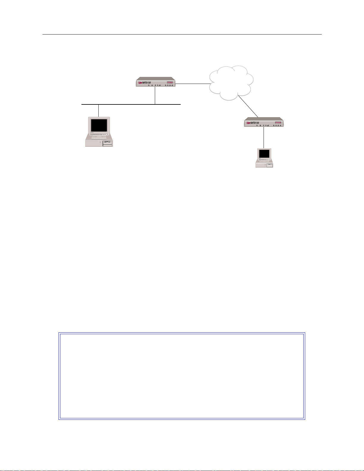
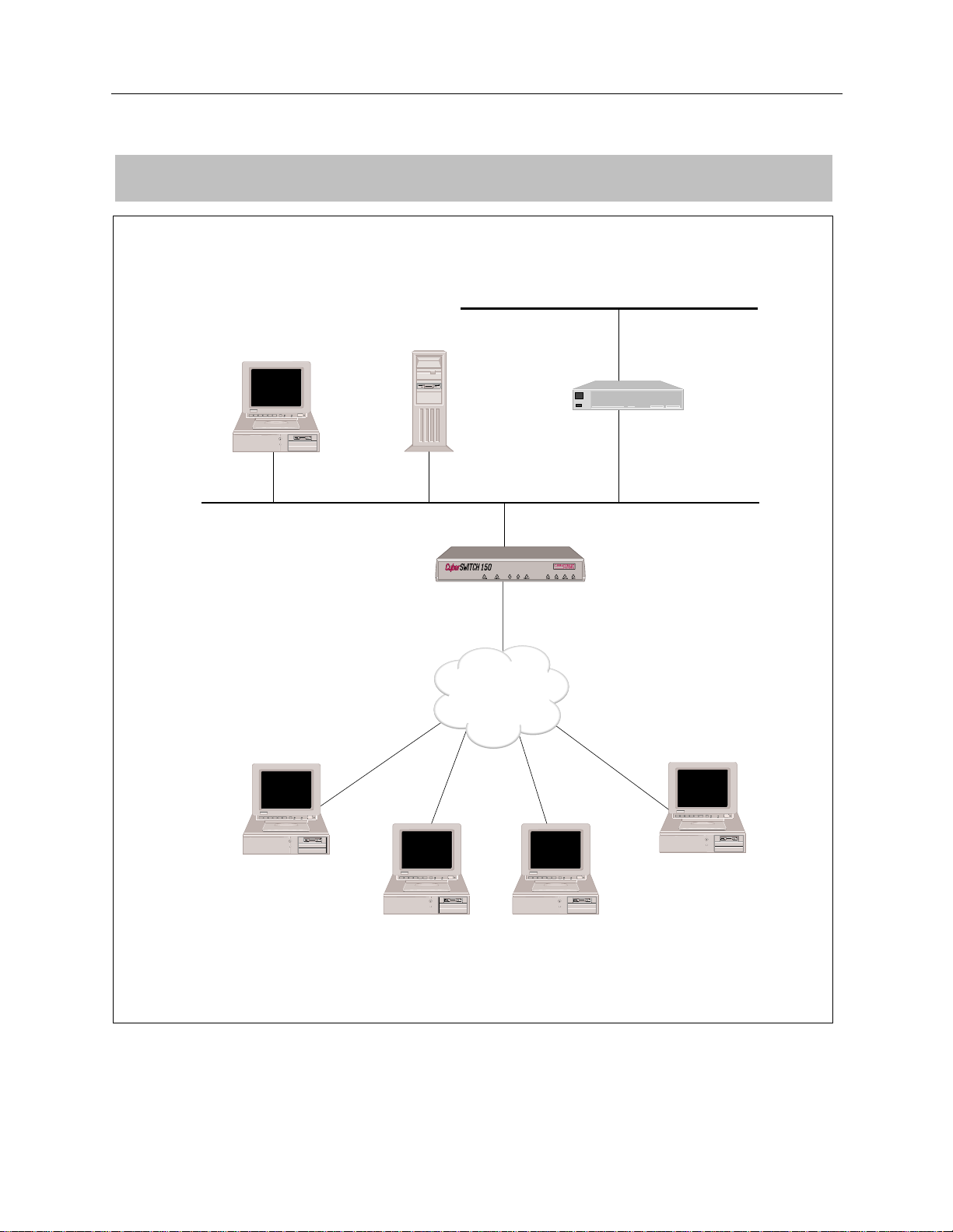
This chapter provides an example of a simple network using remote bridge devices to access four
basic rate lines in the CyberSWITCH. Bridges are formed between each of the LANs to which the
remote bridge device s are connected, and the LAN to which the Cyb erSWITCH is connected.
The following section provides the initial installation steps that would be used with any type of
network in stallation.
INITIAL INSTALLATION STEPS
The initial steps in the CyberS WIT CH insta llati on process ar e basica lly the same no matt er how
complicated the network. These steps are:
• completing the requirement worksheets
•ordering ISDN service
• powering on the sy stem
• accessing Release Notes
• connecti ng an administration console
• setting up Telnet access
• upgrading syste m s of t wa re
• changing defaults to secure system
• returning configuration to factory defaults
The chapt e rs Accessing the CyberSWITCH and Upgrading System Software (in the User’s Guide)
describe each of these steps in detail.
Worksheets for this network are included on the next few pages.
CONFIGURING THE SIMPLE REMOTE BRIDGE
Because this is a simple bridged network, you only need to fill out the System Details and Bridging
and Routing Information worksheets. The worksheets for Example 1 are on the following pages.
Page 10

EXAMPLE NETWORKS
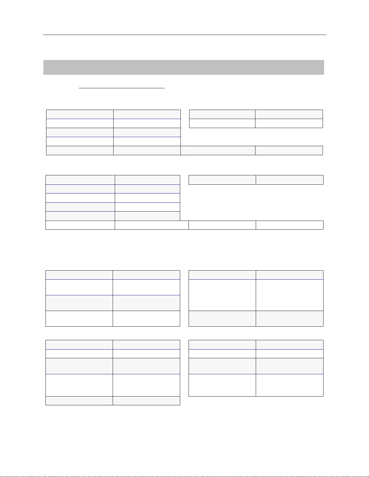
SYSTEM DETAILS
System Name:
SITE1
PAP Password:_______________ CHAP Secret:___________________
RESOURCES
Type Slot Switch type Synchronization type
BRI 1 5ESS
Ethernet_1 2
LINES
BRI Lines
Name Slot Port Line type Call screen TEI SPID Di rectory number
Line1 1 1 PPP Auto
PRI Lines
Name Slot Port Framing type Line coding Sig. method Line build-out
V.35 and RS232 Lines
Name Slot Port Device/Net wo rk Idle character
10 CyberSWITCH
Page 11

BRIDGING
BRIDGING AND ROUTING INFORMATION
S
IMPLE REMOTE BRIDGING NETWORK
Bridging and Routing Information
Bridging
Mode of Operation ❒ restricted ❒ unrestricted
Bridge Filters
Bridge Dial Out/
Known Connect List
IP ROUTING
IP Routin g
Mode of Operation ❒ router
Network Interface Information
LAN Name
Unnu m b e red W A N ❒ need
Remote LAN Name
Tradition al WAN Name
Direct Host WAN Name
IP Host Mode IP address
X
enabled ❒ disabled
X
enabled ❒ disabled
X
IP host
IP address
Mask
❒ don’t need
IP address
Mask
IP address
Mask
IP address
Mask
Mask
192.42.1.6 192.42.1.7
Static Routes
Destination network address Mask Next hop
❒ default?
❒ default?
❒ default?
❒ default?
Small Office Remote Access Switch 11
Page 12

EXAMPLE NETWORKS
CONFIGURE THE CYBERSWITCH
Using CFGEDIT, we will guide you through the steps to configure the CyberSWITCH for a simple
remote bridge network. We will execute these steps in the same order as they appear in the
configuration menus.
Start the CFGEDIT configura tion utility . Type the foll owing comm a nd at the system prom p t:
cfgedit
The following Main Menu will then be displayed:
Main Menu:
1) Physical Resources
2) Options
3) Security
4) Save Changes
Select function from above or <RET> to exit:
<return>
C
ONFIGURING THE PHYSICAL RESOURCE INFORMATION
We start with confi guring the P hysical Resou rce information. Pr e ss 1 at the Main Menu to display
the Physical Resource Configuration Menu:
Physical Resource Menu:
1) Resources
2) Data Lines
3) Access
4) ISDN Subaddress
Select function from above or <RET> for previous menu:
You may only configure th e switch type. The rest of the resource information may only be
displayed.
We will next add the line in formation . Press 2 at the Physic al Resour ces Menu and pres s 1 to add a
line. First, you will be prompted for the line name. You will then be asked to select which slot and
port you wish to use. We will use LINE1 as the line name, and slot 1, port 1 as the slot and port
combination:
LINE NAME or press <RET> for previous menu: LINE1
Currently available Ports:
SLOT Resource Type Available Ports Switch Type
---- --------------- ----------------- ---------------
1 BASIC_RATE 1, 2, 3, 4 BRI_5ESS
Slot number from above? 1
Port number from Slot 1? 1
You will then be prompted for the line interface type. For our example, we will be using point-to-
point lines. Press 1 as shown below to select this line type.
12 CyberSWITCH
Page 13

S
IMPLE REMOTE BRIDGING NETWORK
Bridging and Routing Information
LINE TYPE = BR_ISDN
1) POINT_TO_POINT
2) POINT_MULTIPOINT
Select Option [default = POINT_TO_POINT] or press <RET> for previous menu: 1
The next item th at you need to c onfigure is the Dat a Link for t he line. Depending on the switch type,
there may be more than one Data Link per line. In our ex ample, we use one Data Link with
Automatic TEI Negotiat ion:
Current DATA LINK Configuration for this line:
id TEI
-- ----
There are currently no Data Links configured for this line.
Enter (1) to Add or press <RET> for previous menu: 1
Automatic TEI Negotiation (Y or N) [default = Y]? Y
Current Data Link Configuration for this line:
id TEI
-- ----
1 AUTO
(1) Add, (2) Change, (3) Delete a DATA LINK or press <RET> for previous menu? <RET>
After entering the above information, press <return> to display the lin e menu.Press <return> twice
to retu rn to th e Main Me nu .
C
ONFIGURING THE OPTIONS
The default configuration for the CyberSWITCH is bridging disabled and IP routing enabled. For
reasons we provide below, we want both bridging and IP routing enabled. Under the Option Menu,
select the bridging option and follow the instructions to enable bridging.
This network is a bridged network, but we are going to configure an IP option (the IP host operating
mode) so that we may use an IP application (such as Telnet, TFTP, or SNMP) to manage the
CyberSWITCH. Refer to the graphic below for clarification.
Small Office Remote Access Switch 13
Page 14
EXAMPLE NETWORKS
CSX150
ISDN
CSX150
"SITE2"
IP Host Interface
192.42.1.7
192.42.1.0
Telnet Client
"SITE1"
IP Host Interface
192.42.1.6
The network illustrated above is a bridged network. Each system, SITE1 and SITE2 have been
configured with all the necessar y bridging informati on. SITE1 and S ITE2 have also been configured
in the IP host operating mode, and each have an IP host interface. This will allow each system to be
managed remotely by the PC using Telnet client software (once the initial configuration has been
completed).
Note that th e IP add ress associated with each sys te m is on the same LAN as the PC. This does not
have to be the case. As long as the P C h a s access to the systems thro u gh their IP addresses, it can
manage the systems using Telnet (or one of the oth e r IP applicati ons).
The steps below describe the configuration steps needed for the above example:
To enable the IP Host Operat ing Mode:
1. Select IP Operating Mode fr om the IP configuration menu.
2. Select IP host operating mode.
Note: The IP operating mode can not be set to host unless bridging is enabled.
3. When you select the IP host operating mode, an abbreviated IP configuration will be displayed
(similar to the following ):
IP Menu:
1) IP Routing (Enable/Disable)
2) IP Operating Mode
3) IP Interfaces
4) IP Static Routes
5) RIP (Enable/Disable)
6) IP Static ARP Table Entries
7) Isolated Mode (Enable/Disable)
8) Static Route Lookup via RADIUS (Enable/Disable)
9) IP Address Pool
10) IP Filter Information
11) DHCP Information
Select function from above or <RET> for previous menu:
14 CyberSWITCH
Page 15

S
IMPLE REMOTE BRIDGING NETWORK
Bridging and Routing Information
To configure the IP host interface:
1. Select IP Interfaces from the IP configuratio n men u.
2. Select to add an interface.
3. Enter the IP address assigned to this interface. For SITE1, this is 192.42.1.6; for SITE2, this is
192.42.1.7.
4. Enter the subne t mask.
5. Ent e r the MT U size.
6. Select the transmit broad cast address.
If IP RIP is enabled, enter the following additional inf orm ation:
7. IP RIP receive control.
8. IP RIP respond con trol.
9. IP RIP v2 authentication control.
10. IP RIP v2 auth e ntication key (required only if the IP RIP v2 authentication control has been
config u r e d wi th a value other tha n “No Au thenticatio n.“
For more detailed information on the IP host operating mode, refer to the IP Operating Mode section
in the Configuring Basic IP Routing chapter of the User’s Guide.
C
ONFIGURING THE SECURITY
For this network configuration, we require no security. The default configuration is device security
enabled. To make the required configuration change, select Security from the Main Menu. Then
select Security Level. Finally, select No Security.
SAVE CONFIGURATION FILES
We have now configured all of the required information. Press 4 from the Main menu to save the
changes and then press <RET> to exit. Reboot the system to activate your changes.
Small Office Remote Access Switch 15
Page 16

EXAMPLE NETWORKS
VERIFY THE INSTALLATION
Steps on how to verify the installation are detailed in the System Verification chapter of the User’s
Guide. This section gives an outline of which steps should be executed.
On the CyberSWI TCH:
Verify resources are operational
Issue
dr
Look for BRI lin e me ssages
Look for LAN initialized messages
Look for Bridge initializ ed mes s age s
Verify WAN Lin es Av ai lab le
Connect WAN lines
Issue
dr
Look for “Data Link up 1,1” in reports
On each Combinet LAN:
Attempt accessing a resource on the system LAN. This may require that you reboot y ou r machine
and proceed through the logon sequence.
command
command
16 CyberSWITCH
Page 17

R
EMOTE BRIDGING NETWORK WITH SECURITY
OVERVIEW
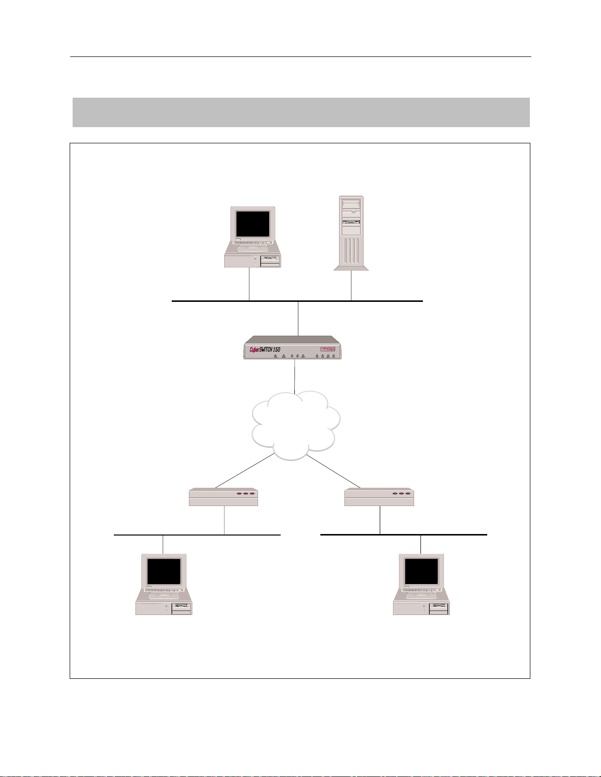
This example network is a bridged network with Calling Line Id security and Bridge MAC Address
security enabled. The network is configured with two devices. One device will be configured to
require a Bridge MAC Address security password, and one device will not. This network uses BRI
lines.
Worksheets for this network are included on t he following pages.
Note that a Hunt Group i s used for the BRI lines pictured in the Network Topology Worksheet.
Remote devi ce s wil l then on ly nee d to con fig ure on e tel ephon e numbe r (t he Hunt Group n umber)
for the CyberSWITCH instead of all four phone numbers. If the first line is busy, the next line is
automatically used, and so on until a free line is found. A Hunt Group number can be arranged
through your Service Provider.
INITIAL INSTALLATION STEPS
The initial steps in the CyberS WIT CH insta llati on process ar e basica lly the same no matt er how
complicated the network. These steps are:
• completing the requirement worksheets
•ordering ISDN service
• powering on the system
• accessing Release Notes
• connecting an administrati on console
• setting up Telnet access
• upgrading syste m s of t wa re
• changing defaults to secure system
• returning configuration to factory defaults
The chapt e rs Accessing the CyberSWITCH and Upgrading System Software (in the User’s Guide)
describe each of these steps in detail.
Worksheets for this network are included on the next few pages.
Page 18
EXAMPLE NETWORKS
NETWORK TOPOLOGY
13135551212
13135552121
Bridge Ethernet Address:
000123456789
Password: JXF30
BRI
PC
CSX150
13135551111
13135551112
BRI
ISDN
File Server
Hunt Group Number:
13135551111
BRI
13135556789
13135559876
Bridge Ethernet Address:
003456789000
Password: None
18 CyberSWITCH
PC
User Name:
Mike Mann
User Name:
Pat Smith
PC
Page 19

SYSTEM DETAILS
R
EMOTE BRIDGING NETWORK WITH SECURITY
Initial Installation Steps
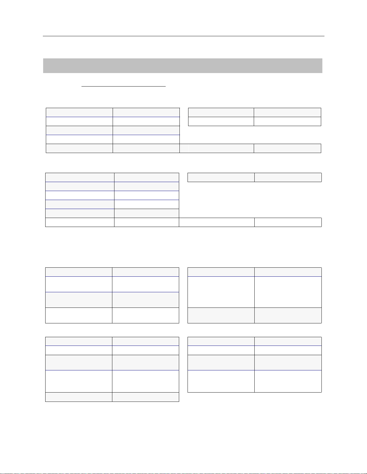
System Name:
Remote Bridge
PAP Password:____________ ___ CHAP Secret:_____ ______________
RESOURCES
Type
BRI 1 NI-1
Ethernet_1 2
Slot Switch type Synchronization type
LINES
BRI Lines
Name Slot Port Line type Call
screen
Line1 1 1 PPP Auto 3135551111 13135551111*
TEI SPID Directory
3135551112 13135551112*
number
* Hunt Group Number: 13135551111
Small Office Remote Access Switch 19
Page 20
EXAMPLE NETWORKS
DEVICE INFORMATION
Devi ce N ame:
Mike Mann
Calling (ISDN, FR, etc.) Information X.25 Information
Line Protocol
Base Data Rate SVC
Initial Data Rate
Max Data Rate
Dial-Out Number(s)
Authentication Information
PAP Password DLCI
CHAP Secret
IP Host ID
Bridge Ethernet Address*
Bridge Password*
CLID(s)
* HDLC Bridge only
Protocol fo r th is pa rt ic ul a r devi ce?
HDLC bridge
:
PVC
Frame Relay Information
000123456789
JXF30
13135551212 13135552121
Bridge IP
Bridging enabled? ❒ enabled ❒ disabled IP enabled? ❒ enabled ❒ disabled
Make calls
for bridged data?
For IP RLAN, IP (Sub-)
network number
For IPX RLAN, external
network number
❒ enabled ❒ disabled IP Address
(on WAN link)
Make calls f or IP data? ❒ enabled ❒ disabled
❒ 0.0.0.0 if
unnumbered link
IPX AppleTalk
IPX enabled? ❒ enabled ❒ disabled AppleTalk enabled? ❒ enabled ❒ disabled
Callable by IPX? ❒ enabled ❒ disabled AppleTalk Address
IPXWAN protocol? ❒ enabled ❒ disabled Make calls f o r
AT data?
IPX routing protocol?
IPX spoofing?
❒ none
❒ RIP/SAP
❒ triggered RIP/SAP
AT Routing Protocol
❒ enabled ❒ disabled
20 CyberSWITCH
Page 21
R
EMOTE BRIDGING NETWORK WITH SECURITY
DEVICE INFORMATION
Device Information
Devi ce N ame:
Pat Smith
Calling (ISDN, FR, etc.) Information X.25 Information
Line Protocol
Base Data Rate SVC
Initial Data Rate
Max Data Rate
Dial-Out Number(s)
Authentication Information
PAP Password DLCI
CHAP Secret
IP Host ID
Bridge Ethernet Address*
Bridge Password*
CLID(s)
* HDLC Bridge only
Protocol fo r th is pa rt ic ul a r devi ce?
HDLC bridge
:
PVC
Frame Relay Information
003456789000
13135556789 13135559876
Bridge IP
Bridging enabled? ❒ enabled ❒ disabled IP enabled? ❒ enabled ❒ dis abled
Make calls
for bridged data?
For IP RLAN, IP (Sub-)
network number
For IPX RLAN, external
network number
❒ enabled ❒ disabled IP Address
(on WAN link)
Make calls f or IP data? ❒ enabled ❒ disabled
❒ 0.0.0.0 if
unnumbered link
IPX AppleTalk
IPX enabled? ❒ enabled ❒ disabled AppleTalk enabled? ❒ enabled ❒ disabled
Callable by IPX? ❒ enabled ❒ disabled AppleTalk Address
IPXWAN protocol? ❒ enabled ❒ disabled Make calls f o r
AT data?
IPX routing protocol?
IPX spoofing?
❒ none
❒ RIP/SAP
❒ triggered RIP/SAP
AT Routing Protocol
❒ enabled ❒ disabled
Small Office Remote Access Switch 21
Page 22

EXAMPLE NETWORKS
BRIDGING
Bridging X enabled ❒ disabled
Mode of Operation ❒ restricted ❒ unrestricted
Bridge Filters
Bridge Dial Out/
Known Connect List
IP ROUTING
BRIDGING AND ROUTING INFORMATION
IP Routin g
Mode of Operation ❒ router ❒ IP host
Network Interface Information
LAN Name
Unnu m b e red W A N ❒ need
Remote LAN Name
Tradition al WAN Name
Direct Host WAN Name
IP Host Mode IP address
X
enabled ❒ disabled
IP address
Mask
❒ don’t need
IP address
Mask
IP address
Mask
IP address
Mask
Mask
Static Routes
Destination network address Mask Next hop
22 CyberSWITCH
❒ default?
❒ default?
❒ default?
❒ default?
Page 23

CONFIGURE THE CYBERSWITCH
Note: We are assuming that the softwar e ha s al ready been installed and is running. Be sure you
are working from the system prompt.
Using the detailed instructions for these steps found in the Simple Remote Bridging chapter,
complete the following configurat ion step s.
Start the Run-Time CFGEDIT program
Select physical resources
Select to add a resource
Select Switch type to be NI-1
Select to add a line
Enter the line name
Select slot and port numbers
Select line interface type of “P oint-to-Point”
Add Data Links (Data Link explanati on follows)
Choose Auto TEI Neg otiation
Enter Service Profile ID (SPID) Value
Enter Directory Number for Data Link
Enter Maximum Number of Digits to Verify
Repeat “Add Data Links” for second Data Link
Repeat “Select to add a line” for each additional line
R
EMOTE BRIDGING NETWORK WITH SECURITY
Configure the CyberSWITCH
Data links are handled differently on a NI-1 switch. Some BRI lines have only one phone number
(for the Data Link), but can handle two calls (one for each bearer channel). For NI-1 switches, the
BRI line has two phone numbers (one for each bearer channel), and each phone number has it s own
SPID. You must enter the number of d igits to verify, so that when the system receives a phone ca ll
it can determine on which bearer to accept the phone call. Refer to the System Details worksheet for
the SPIDs, directory n umbers, and the number of digits to verify.
CONFIGURING THE OPTIONS
The default configuration for the CyberSWITCH is bridging disabled and IP routing enabled. For
reasons we provide below, we want both bridging and IP routing enabled. Under the Option Menu,
select the bridging option and follow the instructions to enable bridging.
This network is a bridged network, but we are going to configure an IP option (the IP host operating
mode) so that we may use an IP application (such as Telnet, TFTP, or SNMP) to manage the
CyberSWITCH. This process was described in the previous chapter (page 13) and will not be
repeated here.
Small Office Remote Access Switch 23
Page 24

EXAMPLE NETWORKS
CONFIGURING THE SECURITY
This network has remote devices, and the device informat ion for each of those devices must be
configured. Device security is used, and th e remote devices are configured in th e on-node
authentication data base. Device secu rity using a on-node authent ic a tion database are the default
values.
To begin the security configuration, press 3 at the Main CFGEDIT Menu. The Security Menu will
then be displayed as follow s :
Security Menu:
1) Security Level
2) System Options and Information
3) Device Level Databases
4) User Level Databases (Enable/Disable)
5) Off-node Server Information
6) Network Login Information
Select function from above or <RET> for previous menu:
C
ONFIGURING THE SECURITY LEVEL
From the Security Menu, press 1, Security Level. Then press 2 to enable Device Level Security:
Security Level Menu:
1) No Security
2) Device Level Security
3) User Level Security
4) Device and User Level Security
Select function from above or <RET> for previous menu:
After enabling Device Level S e curity, return to the Security Menu .
C
ONFIGURING THE SYSTEM OPTIONS AND INFORMATION
The default configuration for System Options is all security options enabled, which is acceptable
for this network. No Sys te m Information or Administration Sessions are required. Theref ore, no
changes are n ecessary.
C
ONFIGURING THE DEVICE LEVEL DATABASE
From the Secu rity Menu, press 3 to displa y the Device Level Database Menu . To enable the Onnode Device Database, press 1 and follow th e on-screen instruct ions:
Device Level Databases Menu:
1) On-node Device Database (Enable/Disable)
2) On-node Device Entries
3) Off-node Device Database Location
Select function from above or <RET> for previous menu:
24 CyberSWITCH
Page 25

R
EMOTE BRIDGING NETWORK WITH SECURITY
Configure the CyberSWITCH
Press 2 to configure the information for our f irst device, Mike Mann. Press 1 to add a device. You
will first be asked to enter the Device Name:
Device Name? Mike Mann
After the new device name has been specified, a screen similar to the following is displayed.
Device Table Menu: (Device = "Mike Mann")
1) ISDN
2) Frame Relay
3) X.25
4) Authentication
5) IP
6) IPX
7) AppleTalk
8) Bridging
9) POTS
10) Compression
Select function from above or <RET> for previous menu:
Information for the new device may be configured in any order. You have control over how much
information is specified for each device, and the order in which it is entered.
We will begin by specifying the type of device. We need to determine if the device will use ISDN
Line Protoc ol (choic e 1), Frame Relay (choic e 2) , or X. 25 (choice 3 ).T his d evice i s an ISDN devic e, so
we will press 1 for “ISDN Information” from the Device Table Configuration Menu.
The ISDN Configuration Menu will then be displayed with the preconfigured default values:
Device ISDN Menu: (Device = "Mike Mann")
1) ISDN Line Protocol "PPP (Point to Point Protocol)"
2) Base Data Rate "64000 bps"
3) Initial Data Rate "64000 bps"
4) Maximum Data Rate "128000 bps"
5) Dial Out Phone Number(s) ""
6) Subaddress ""
7) Profile Name "Default_Profile"
8) H0 Call Support ENABLED
Select function from above or <RET> for previous menu:
We do not want to use th e default ISDN Line Protocol of PPP. Press 1 to configure this device’ s
ISDN line protocol. The device Mike Mann uses HDLC protocol, so we will press 2:
Device ISDN Line Protocol Menu: (Device = "Mike Mann")
1) PPP (Point to Point Protocol)
2) HDLC Bridge
3) IP Host (RFC1294)
Select option to associate with device "Mike Mann",
or "0" to disable ISDN access for this device [default = 1]? 2
Small Office Remote Access Switch 25
Page 26

EXAMPLE NETWORKS
The only other item on the Device ISDN Line Protoc ol Menu that this type of device needs is the
maximum data rate. We will accept the default value of 128,000 bps. No changes are required.
Return to th e Device Tab le Menu.
At the Device Table Menu, press 4 to enter the authe ntication information needed for th is device.
The authentication information needed for each device depends on the device type.
For device “Mike Mann,” we opt to configure a bridge Ethernet address (000123456789), we will
assign a bridge password (JXF30), and configure a first and second calling line Id. After the device
authentication has been entered for device “Mike Mann,” the screen will appear as follows:
Device Authentication Menu: (Device = "Mike Mann")
PPP:
1) PAP Password ""
2) CHAP Secret ""
3) Outbound Authentication ENABLED
4) User Level Authentication DISABLED
IP Host (RFC 1294):
5) IP Host Id ""
HDLC Bridge:
6) Bridge Ethernet Address "000123456789"
7) Bridge Password "JXF30"
ISDN:
8) Calling Line Id(s) "13135551212"
"13135552121"
Select function from above or <RET> for previous menu:
Next, enter the device info rma ti on for Pat Smit h. Th is dev ice is also an HDLC bridge , and is
configured using the same type of authentication as device Mike Mann, except we will configure
no password for device Pat Smith . Enter 003456789000 for th e bridge Ethernet address,
13135556789 for the first calling line Id, and 13135559876 for the second calling line Id.
The following screen will be displayed after information for both devices in our network has been
entered:
CURRENT DEVICE TABLE (Sorted by Device Name in Ascending ASCII Order)
id Device Name
---------------------------1 "Mike Mann"
2 "Pat Smith"
(1) Add, (2) Change, (3) Delete, (4) Display a Device or press <RET> for previous menu?
26 CyberSWITCH
Page 27

SAVE CONFIGURATION FILES
We have now configured all of the required information for a bridged system with Calling Line Id
Security and Bridge MAC Add ress Sec urit y enable d. Pr ess 4 at the Mai n menu t o save th e changes.
The old configuration files w ill be stored in the \CON FIG direc tor y with a file extensio n of .BAK
(e.g., the old NODE.NEI file will be called NODE.BAK).
After you sa ve the configu ration files, press <RET > to exit the CFGEDIT program. Re boot the
system to a ctivate your changes.
VERIFY THE INSTALLATION
Steps on how to verify the installation are detailed in the System Verification chapter of the User’s
Guide. This section gives an outline of which steps should be executed.
On the CyberSWI TCH:
Verify hardware resources are operational
Issue
dr
Look for BRI messages
Look for LAN initialized messages
Verify WAN Lin es Av ai lab le
Connect WAN lines
Issue
dr
Look for “Data Link up 1,1” in reports
command
command
R
EMOTE BRIDGING NETWORK WITH SECURITY
Verify the Installation
On eac h HD LC Bridge LAN:
Attempt ac cessing a re source on the Cy berSWITCH LAN. Th is may require th at you reboot
your system and proceed through the logon sequence.
Small Office Remote Access Switch 27
Page 28

IP R
OUTING NETWORK
OVERVIEW
This sample network has an IP network with devices accessing the network f rom their homes.
INITIAL INSTALLATION STEPS
The initial steps in the CyberS WIT CH insta llati on process ar e basica lly the same no matt er how
complicated the network. These steps are:
• completing the requirement worksheets
•ordering ISDN service
• powering on the system
• accessing Release Notes
• connecting an administrati on console
• setting up Telnet access
• upgrading syste m s of t wa re
• changing defaults to secure system
• returning configuration to factory defaults
The chapt e rs Accessing the CyberSWITCH and Upgrading System Software (in the User’s Guide)
describe these step s in detail.
Worksheets for this network are included on the next few pages.
Page 29
IP R
OUTING NETWORK
Initial Installation Steps
NETWORK TOPOLOGY
LAN 131.1.0.0
PC
SITE:
San Fran
Host
File Server
BRI
BRI
BRI
ISDN
Router 1 131.1.1.16
128.1.1.1
WAN Interface 192.1.1.1
BRI
BRI
128.1.1.16
Host
192.1.1.2
Rick Bear
Host
192.1.1.3
Victoria Moose
Host
128.1.1.3
Todd Jones
128.1.1.2
Jill Smith
Small Office Remote Access Switch 29
Page 30

EXAMPLE NETWORKS
SYSTEM DETAILS
System Name:
IP Network
PAP Password:__________ _____ CHAP Se cret: __________ ______ ___
RESOURCES
Type Slot Switch type Synchronization type
BRI 1
Ethernet_1 3
LINES
BRI Lines
Name Slot Port Line type Call screen TEI SPID Di rectory number
line1 1 1 Auto
NTT
30 CyberSWITCH
Page 31

DEVICE INFORMATION
IP R
OUTING NETWORK
Device Information
Devi ce N ame:
Rick Bear
Calling (ISDN, FR, etc.) Information X.25 Information
Line Protocol PVC
Base Data Rate SVC
Initial Data Rate
Max Data Rate
Dial-Out Number(s)
Authentication Information
PAP Password DLCI
CHAP Secret
IP Host ID
Bridge Ethernet Address*
Bridge Password*
CLID(s)
* HDLC Bridge only
Protocol fo r th is pa rt ic ul a r devi ce?
:
RICK
Frame Relay Information
Bridge IP
Bridging enabled? ❒ enabled ❒ disabled IP enabled? X enabl ed ❒ disabl ed
Make calls
for bridged data?
For IP RLAN, IP (Sub-)
network number
For IPX RLAN, external
network number
❒ enabled ❒ disabled IP Address
(on WAN link)
Make calls f or IP data? ❒ enabled ❒ disabled
192.1.1.2
❒ 0.0.0.0 if
unnumbered link
IPX AppleTalk
IPX enabled? ❒ enabled ❒ disabled AppleTalk enabled? ❒ enabled ❒ disabled
Callable by IPX? ❒ enabled ❒ disabled AppleTalk Address
IPXWAN protocol? ❒ enabled ❒ disabled Make calls f o r
AT data?
IPX routing protocol?
IPX spoofing?
❒ none
❒ RIP/SAP
❒ triggered RIP/SAP
AT Routing Protocol
❒ enabled ❒ disabled
Small Office Remote Access Switch 31
Page 32

EXAMPLE NETWORKS
DEVICE INFORMATION
Devi ce N ame:
Jill Smith
Calling (ISDN, FR, etc.) Information X.25 Information
Line Protocol PVC
Base Data Rate SVC
Initial Data Rate
Max Data Rate
Dial-Out Number(s)
Authentication Information
PAP Password DLCI
CHAP Secret
IP Host ID
Bridge Ethernet Address*
Bridge Password*
CLID(s)
* HDLC Bridge only
Protocol fo r th is pa rt ic ul a r devi ce?
:
JILL
Frame Relay Information
Bridge IP
Bridging enabled? ❒ enabled ❒ disabled IP enabled? X enabl ed ❒ disabl ed
Make calls
for bridged data?
For IP RLAN, IP (Sub-)
network number
For IPX RLAN, external
network number
❒ enabled ❒ disabled IP Address
(on WAN link)
Make calls f or IP data? ❒ enabled ❒ disabled
128.1.1.2
❒ 0.0.0.0 if
unnumbered link
IPX AppleTalk
IPX enabled? ❒ enabled ❒ disabled AppleTalk enabled? ❒ enabled ❒ disabled
Callable by IPX? ❒ enabled ❒ disabled AppleTalk Address
IPXWAN protocol? ❒ enabled ❒ disabled Make calls f o r
AT data?
IPX routing protocol?
IPX spoofing?
❒ none
❒ RIP/SAP
❒ triggered RIP/SAP
AT Routing Protocol
❒ enabled ❒ disabled
32 CyberSWITCH
Page 33

DEVICE INFORMATION
IP R
OUTING NETWORK
Device Information
Devi ce N ame:
Ralph Moose
Calling (ISDN, FR, etc.) Information X.25 Information
Line Protocol PVC
Base Data Rate SVC
Initial Data Rate
Max Data Rate
Dial-Out Number(s)
Authentication Information
PAP Password DLCI
CHAP Secret
IP Host ID
Bridge Ethernet Address*
Bridge Password*
CLID(s)
* HDLC Bridge only
Protocol fo r th is pa rt ic ul a r devi ce?
:
RALPH
Frame Relay Information
Bridge IP
Bridging enabled? ❒ enabled ❒ disabled IP enabled? X enabl ed ❒ disabl ed
Make calls
for bridged data?
For IP RLAN, IP (Sub-)
network number
For IPX RLAN, external
network number
❒ enabled ❒ disabled IP Address
(on WAN link)
Make calls f or IP data? ❒ enabled ❒ disabled
192.1.1.23
❒ 0.0.0.0 if
unnumbered link
IPX AppleTalk
IPX enabled? ❒ enabled ❒ disabled AppleTalk enabled? ❒ enabled ❒ disabled
Callable by IPX? ❒ enabled ❒ disabled AppleTalk Address
IPXWAN protocol? ❒ enabled ❒ disabled Make calls f o r
AT data?
IPX routing protocol?
IPX spoofing?
❒ none
❒ RIP/SAP
❒ triggered RIP/SAP
AT Routing Protocol
❒ enabled ❒ disabled
Small Office Remote Access Switch 33
Page 34

EXAMPLE NETWORKS
DEVICE INFORMATION
Devi ce N ame:
Todd Jones
Calling (ISDN, FR, etc.) Information X.25 Information
Line Protocol PVC
Base Data Rate SVC
Initial Data Rate
Max Data Rate
Dial-Out Number(s)
Authentication Information
PAP Password DLCI
CHAP Secret
IP Host ID
Bridge Ethernet Address*
Bridge Password*
CLID(s)
* HDLC Bridge only
Protocol fo r th is pa rt ic ul a r devi ce?
:
TODD
Frame Relay Information
Bridge IP
Bridging enabled? ❒ enabled ❒ disabled IP enabled? X enabl ed ❒ disabl ed
Make calls
for bridged data?
For IP RLAN, IP (Sub-)
network number
For IPX RLAN, external
network number
❒ enabled ❒ disabled IP Address
(on WAN link)
Make calls f or IP data? ❒ enabled ❒ disabled
128.1.1.3
❒ 0.0.0.0 if
unnumbered link
IPX AppleTalk
IPX enabled? ❒ enabled ❒ disabled AppleTalk enabled? ❒ enabled ❒ disabled
Callable by IPX? ❒ enabled ❒ disabled AppleTalk Address
IPXWAN protocol? ❒ enabled ❒ disabled Make calls f o r
AT data?
IPX routing protocol?
IPX spoofing?
❒ none
❒ RIP/SAP
❒ triggered RIP/SAP
AT Routing Protocol
❒ enabled ❒ disabled
34 CyberSWITCH
Page 35

BRIDGING
Bridging ❒ enabled ❒ disabled
Mode of Operation ❒ restricted ❒ unrestricted
Bridge Filters
Bridge Dial Out/
Known Connect List
IP ROUTING
BRIDGING AND ROUTING INFORMATION
IP R
OUTING NETWORK
Bridging and Routing Information
IP Routin g
Mode of Operation
Network Interface Information
LAN Name
Unnumbered WAN ❒ need
Remote LAN Name
Traditional WAN Name
Direct Host WAN Name
IP Host Mode IP address
X
enabled ❒ disabled
X
router ❒ IP host
IP address
Mask
❒ don’t need
IP address
Mask
IP address
Mask
IP address
Mask
Mask
(unnumbered)
SanFra n
128.1.1.1
SanJose
192.1.1.1
Monterey
Static Routes
Destination network address Mask Next hop
❒ default?
❒ default?
❒ default?
❒ default?
Small Office Remote Access Switch 35
Page 36

EXAMPLE NETWORKS
CONFIGURE THE CYBERSWITCH
Note: The software should have alr e ady been installed and you should see th e system prompt
before proceeding with these steps.
Using the detailed instructions for these steps found in the Simple Remote Bridging chapter,
complete the following configurat ion step s.
Start the CFGEDIT program
Select physical resources
Select to add a resource
Select Switch type to be 4ESS
Select to add a line
Enter “Line1” as the line na me
Select slot 1, port 1
Add Data Links
Choose Auto TEI Neg otiation
Enter SPID Val ue
Enter Directory Number for Data Link
Enter Maximum Number of Digits to Verify
Repeat “Add Data Links” for second Data Link
The following sections provide instructions for completing the remaining configuration steps.
CONFIGURING THE CYBERSWITCH OPTIONS
To begin the configurati on of th e system options, press 2 at the Main Menu. The following op tions
menu will then be displayed:
Options Menu:
1) Bridging
2) IP
3) IPX Routing
4) AppleTalk
5) SNMP
6) PPP
7) Call Control Options
8) Default Line Protocol
9) Log Options
10) Compression
Select function from above or <RET> for previous menu:
For this example, we only need IP routing enabled. IP routing is already enabled as fault, so no
change is necess ary.
For this example, the only other IP information we need to configure is for IP interfaces. No static
routes are needed because Router 1 supports RIP, which eliminates the need to manually configure
a static route. The next section will provide the instructions needed to configure the necessary IP
interfaces.
36 CyberSWITCH
Page 37

CONFIGURING THE IP INTERFACE INFORMATION
In our example, we need to configure three types of interfaces (refer to the Network Topology
Worksheet). The LAN type network interface represents the system connection to the IP Network
128.1.0. 0 on the LAN. The WAN (Direct Host) interface is a logical extension of th e LA N IP
network. Di rect Host r emote I P de vices sh are t he sam e IP add ress space as t he I P netw ork 128.1. 0.0
on the LAN. The WAN network inter f ace is a logical interface to an IP network connected to the
CyberSWITCH over the ISDN. The reason we are using both a WAN and a WAN (Direct Host)
Interfac e is to allow the t wo device s, Ric k Bear and Ralph Moose, t o call into some where el se if need
be.
We will begin by adding the LAN interface. Press 2 at the IP configuration menu to begin the LAN
interface confi gurati on. Press 1 to add an IP int erface. Press 1 to se lect LAN as the type of inter face
that you wish to configure.
The inter f ace name is a symbolic name given to the interface. For the LAN interface, you should
use a name that describes the LAN. It could be the name of the site or department. Type SanFran
for this example.
You will then be asked for the IP Address for the interface. In our exam ple, the value you should
enter is 128.1.1.1. You will then be asked for th e IP Subnet mask information. In our ex ample, we
are using a Clas s B address (without any subnetwork add ressing) that requires 1 6 bits of the
address to define the network number. Therefore, press <return> to accept the default of “16”
significant bits. Press <return> to accept the default packet encapsulation type (Ethernet). Press
<return> to accept the default of 1500 as the MTU size.
IP R
OUTING NETWORK
Configure the CyberSWITCH
Press <re turn> to ac cept the defau lt tr ansmit b roadcast address. For almos t all d evices, this a ddress
will let the broadcast be transmitted to all devices on the local network. For some older devices, you
may need to try some of the other se lections to g et the transmi ssion to work correctly.
The rest of the LA N information requested pertains to the syst e m RI P feature. (This information
will not be asked for if you have disabled RIP.) RIP is a protocol used to exchange routing
inform a ti o n a mo ng IP dev i ce s . Using RIP can au to m a te the mai nte nance of ro u ting tab le s o n IP
devices and relieve you of having to keep the routing tables up to date manually. Static routes need
to be confi gured manu ally if we need to acc ess a WAN networ k that is n ot direc tly connec ted to t he
system, or if we need to acce ss a LAN network thr ough a router that does not supp ort RIP.
RIP det ermines the s hortest pat h betwee n two p oints i n a net work i n terms of th e number of “h ops”
between these points.
For the rest of the required RIP LAN interface information, accept the default values.
Small Office Remote Access Switch 37
Page 38

EXAMPLE NETWORKS
The interactive LAN interface session should be simil ar to the following:
1) LAN
2) WAN
3) WAN (Direct Host)
4) WAN (RLAN)
5) WAN (UnNumbered)
Select function from above or <RET> for previous menu: 1
INTERFACE NAME or <RET> to cancel? SanFran
Enter the IP Address in dotted decimal notation
or <RET> to cancel? 128.1.1.1
Enter the number of significant bits for the Subnet Mask
[default = 16]? <RET>
Enter the packet encapsulation type 1) for ETHERNET 2) for SNAP
[default = ETHERNET]? <RET>
Enter the MTU size in bytes [default = 1500]? <RET>
Transmit Broadcast Address:
1) 128.1.255.255
2) 128.1.0.0
3) 255.255.255.255
4) 0.0.0.0
5) Specify Explicitly
Enter a Transmit Broadcast Address from the above menu [default = 1]? <RET>
RIP Send Control:
1) Do Not Send.
2) RIP Version 1.
3) RIP Version 1 Compatibility.
4) RIP Version 2.
Enter a RIP Send Control from the above menu [default = 2]? <RET>
(
RIP Receive Control:
1) Do Not Receive.
2) RIP Version 1 Only.
3) RIP Version 2 Only.
4) RIP Version 1 or Version 2.
Enter a RIP Receive Control from the above menu [default = 4]? <RET>
RIP Respond Control:
1) Do Not Respond.
2) RIP Version 1 Only.
3) RIP Version 2 Only.
4) RIP Version 1 or Version 2.
Enter a RIP Respond Control from the above menu [default = 4]? <RET>
RIP Version 2 Authentication Control:
1) No Authentication.
2) Simple Password.
Enter a RIP Authentication Control from the above menu [default = 1]? <RET>
38 CyberSWITCH
Page 39

IP R
OUTING NETWORK
Configure the CyberSWITCH
After you have entered all of the information for the interface, a summary screen is displayed. You
are asked if you want to save this information. If all of the configured information is accurate, press
<return> to save the information. If any configuration elem ents need to be changed, press N, and
reconfigure the interface.
Current Configuration for INTERFACE "sanfran":
Interface Type LAN
IP Address 128.1.1.1
Mask 255.255.0.0
MTU (bytes) 1500
Encapsulation Ethernet
LAN Port 1
Transmit Broadcast 128.1.255.255
RIP Configuration:
Send Control RIP Version 1
Receive Control RIP1 or RIP2
Respond Control RIP1 or RIP2
v2 Authentication No Authentication
Are you sure you want to add the INTERFACE "sanfran" (Y or N) [Y]? <RET>
Next, we will configure the system’s WAN interface. This interface is used for the two devices Rick
Bear and Ralph Moose. The in terfac e name is a sym bolic name given to the interf ace. For t he WAN
interface, you should use a name that describes the WAN. For this e xample, both WAN sites are
located in San Jose, so we will enter SanJose for the WAN interface Name.
You will then be asked for the IP Address for the WAN interface. In our exam ple, the value yo u
should enter is 192.1.1.1 (r efer to Network Topology Worksheet). You will then be asked for the IP
Subnet mask information. Pres s <return> to accept the default of “24” signifi cant bits. Press
<return> to acce pt the def ault of 1500 as the MTU s ize. Press <ret urn> to accept the default tr ansmit
broadcast ad dress.
The last configuration elemen t pert ains to the system’s RIP feature. This informa tion will not be
requested if you have di sabled the RIP feature. Here, you have a choice of e nabling or disabling
host routes propagation. The RIP host routes propagation scheme determines how the WAN local
route will be propagated via RIP. The default value is “Host Routes Propagation is currently
DISABLED.” With the default, WAN local routes are propagated as subnetwork routes. If Host
routes propagation is enabled, host routes will be propagated on other network interfaces only
while each remote IP device is con nected to the system.
When the RIP host propagation scheme is enabled, multiple systems on the same LAN will work
properly. RIP information is then advertised as multiple host rout es as they connect to the system.
In our examp le network, th e re is only one system on the LAN. Therefore, we want to leave host
routes propagation disabled.
The following screen illustr ate s the host routes propagati on portion of the e ntry of the WAN
interface information:
Host Routes Propagation is currently DISABLED.
By enabling Host Route Propagation for this interface,
host routes will be propagated on other network interfaces
while each remote IP device is connected to the system.
Do you wish to ENABLE Host Route Propagation (Y or N) [default = N]? <RET>
Small Office Remote Access Switch 39
Page 40

EXAMPLE NETWORKS
The WAN interface summary screen will then be displayed. If all of the configured information is
accurate, press <return> to save th e in f ormation.
Finally, we will enter the interface inf ormation for the WAN ( Direct Host) inte rface. Press 1 t o add
another interface. This interface will be used for devices Jill Smith and Todd Jones. The interface
name is a symbol ic name given to the interface. For the WAN (Direct Host) interfac e , you should
use a name t hat d escri bes th e Di rec t Host WAN. F or th is exa mpl e, bot h Di rect Host WAN site s are
located in Monterey, so we will enter Monterey for the interface Name.
You will also need to enter an MTU value. Press <return> to accept the default of 1500. If all of the
configured information is accurate, press <return> to save the information.
After all three interfaces have been configured, the following screen will be displayed:
Current INTERFACE Configuration:
id Name Type IP address Mask
-- -------------- ---------------------- ------------- --------------1 sanfran LAN 128.1.1.1 255.255.0.0
2 sanjose WAN 192.1.1.1 255.255.255.0
3 monterey WAN (Direct Host) UnNumbered (128.1.1.1)
(1) Add, (2) Change, (3) Delete, (4) Display a INTERFACE or press <RET> for previous menu?
We have now completed the IP information required for this example. Return to the Main Menu.
CONFIGURING THE SECURITY
This example has remote devices, and the device information for each of those devices must be
configured. Device security is used, and th e remote devices are configured in th e on-node
authentication data base. Device secu rity using a on-node authent ic a tion database are the default
values.
To begin the security configuration , press 3 at the Main CFGEDIT Menu to displa y the Se curity
Menu. The sections below provide instructions for configuring the needed security information.
C
ONFIGURING THE SECURITY LEVEL
To begin, press 1 at the Security Menu to display the Security Level Menu. To enable Device level
Security, press 2.
C
ONFIGURING THE SYSTEM OPTIONS AND INFORMATION
The default configuration for System Options is all security options enabled, which is acceptable
for this network. No Sys te m Information or Administration Sessions are required. Theref ore, no
changes are n ecessary.
40 CyberSWITCH
Page 41

CONFIGURING THE DEVICE LEVEL DATABASE
Before beginning, note the following:
The Device Name is the symbolic name for the Device. The Host Id is the information that will be
exchanged when the call is received to ensure only the proper Devices gain access to the system.
The IP Address is simply the IP Address for the device. The IP address must have a valid IP
network in te rface defined for it.
Press 3 at the Security Menu to di splay the Device Level Database Menu. To enable the On- node
Device Database, press 1 and follow the on-screen instructions.
To add the remote devices, press 2 (On-node Device Database entries). Press 1 to confi gure the
information for our first device, Rick Bear:
Device Name? Rick Bear
After the new device name has been specified, a screen similar to the following is displayed. Select
1, ISDN:
IP R
OUTING NETWORK
Configure the CyberSWITCH
Device Table Menu: (Device = "Rick Bear")
1) ISDN
2) Frame Relay
3) X.25
4) Authentication
5) IP
6) IPX
7) AppleTalk
8) Bridging
9) POTS
10) Compression
Select function from above or <RET> for previous menu: 1
The ISDN Configuration Menu then displays preconfigured default values:
Device ISDN Menu: (Device = "Rick Bear")
1) ISDN Line Protocol. "PPP (Point to Point Protocol)"
2) Base Data Rate. "64000 bps"
3) Initial Data Rate. "64000 bps"
4) Maximum Data Rate. "128000 bps"
5) Dial Out Phone Number(s). ""
6) Subaddress. ""
7) Profile Name. "Default_Profile"
8) H0 Call Support DISABLED
Select function from above or <RET> for previous menu:
We do not want to use th e default ISDN Line Protocol of PPP. Press 1 to configure this device’ s
ISDN line protocol. The device Rick Bear uses RFC 1294 protocol, so we will press 3:
Small Office Remote Access Switch 41
Page 42

EXAMPLE NETWORKS
Device ISDN Line Protocol Menu: (Device = "Rick Bear")
1) PPP (Point to Point Protocol)
2) HDLC Bridge
3) IP Host (RFC1294)
Select option to associate with device "Rick Bear",
or "0" to disable ISDN access for this device [default = 1]? 3
The only other item on the Device ISDN Line Protoc ol Menu that this type of device needs is the
maximum data rate. We will accept the default value of 128,000 bps. No changes are required.
Return to th e Device Tab le Menu.
From the Device Table Menu, press 4 to specify Authentication Information:
Device Authentication Menu: (Device = "Rick Bear")
PPP:
1) PAP Password ""
2) CHAP Secret ""
3) Outbound Authentication ENABLED
4) User Level Authentication DISABLED
IP Host (RFC 1294):
5) IP Host Id ""
HDLC Bridge:
6) Bridge Ethernet Address ""
7) Bridge Password ""
ISDN:
8) Calling Line Id(s) ""
Select function from above or <RET> for previous menu:
Since “Rick Bear” is an IP Host Devic e, you must specify an IP Host Id. Press 5. The foll owing screen
is displayed:
IP Host Id [default = NONE]? RICK
“RICK” is the IP Host Id in our example.
At this point, we now need to specify the IP address for “Rick Bear”. Return to the Device Table
Menu and press 5, IP. Enter Rick’s IP address of 192.1.1.2 at the displayed screen :
IP Address in dotted decimal notation or 0.0.0.0 if the device is
over an unnumbered link [default = NONE]? 192.1.1.2
Configuration is now complete for device “Rick Bear.” Following this example, complete the entry
of information for all remainin g devices.
42 CyberSWITCH
Page 43

The following screen will be displayed after all four devices in our example have been entered:
Current Device Table (Sorted by Device Name in Ascending ASCII Order)
id DEVICE NAME
----------------------------1 "Jill Smith"
2 "Rick Bear"
3 "Todd Jones"
4 "Ralph Moose"
(1) Add, (2) Change, (3) Delete, (4) Display a Device or press <RET> for previous
menu?
Return to the Security Con f iguration Menu.
C
ONFIGURING THE USER LEVEL DATABASES
This network doesn’t require the use of a user l evel d atabase. Therefore, no changes are necessar y.
IP R
OUTING NETWORK
Configure the CyberSWITCH
C
ONFIGURING THE OFF-NODE SERVER INFORMATION
The default configuration for Off-node Server Information is None (Use On-node). Since this
network doesn’t require the use of an off-node server, no changes are necessary.
C
ONFIGURING THE NETWORK LOGIN INFORMATION
This netw ork doesn’t require the use of a user level database so network login information
configuration is not necessary.
SAVE CONFIGURATION FILES
We have now configured all t he required information fo r this example. Pre ss 4 from the Main menu
to save the changes. The old configuration files will be stored in the \CONFIG directory with a file
extension of .BAK (e.g., the old NODE.NEI file will be called NODE.BAK).
After you sa ve the configu ration files, press <RET > to exit the CFGEDIT program. Re boot the
system to a ctivate your changes.
Small Office Remote Access Switch 43
Page 44

EXAMPLE NETWORKS
VERIFY THE INSTALLATION
Steps on how to verify the installation are detailed in the System Verification chapter of the User’s
Guide. This section gives an outline of which steps should be executed for Example 3.
On the CyberSWI TCH:
Verify hardware resources are operational
Issue
dr
Look for BRI lin e me ssages
Look for LAN initialized messages
Che c k for IP routing in itialized message in log
Verify WAN Lin es Av ai lab le
Connect WAN lines
Issue
dr
Look for “Data Link up 1,1” in reports
On each Remo te Host:
• Attempt to access a reso urce on the CyberSWITCH LAN. This may require that you reboot
your system and proceed through the logon sequence.
• Have the remote hosts ping the CyberSWITCH.
• Have the CyberSWITCH pin g the remote host s ( if a connection is up).
command
command
44 CyberSWITCH
Page 45

IP R
OUTING NETWORK WITH REMOTE BRIDGE DEVICES
OVERVIEW
This sample network has two remote satellite offices in Monterey and Carmel, California, that need
to be in daily electronic communic a tion with their Corporate Office. Eac h satellit e office ha s an IP
Host that commun ic a t e s throug h a remote b ri dge usi ng the CyberSWITCH’s WAN Remote LAN
(RLAN) interface. The CyberSWITCH treats these devices connected to the RLAN network
interface as if they were connecte d to the same Ethe rnet segment. We will assume in this net work
that we on ly want to route IP traffic onto the corporate LAN, but the same ne twork could be built
to route IPX traffic.
BUSINESS ASSUMPTIONS
• All devices are PPP-compliant.
• Corporate Office (central site) is on a PBX; therefore, 9 required to dial out.
• No File Servers at Carmel or Monterey sites.
• Uses the On-node Device Database for au thentication database.
• Uses P A P to authe ntic a te re m ot e s; CHAP on central site .
• Carmel and Monterey dial into Corporate Office.
• Corporate Office supports two BRI lines (4-port BRI card), with NTT custom switch
configuration.
• Assumes we want to route IP traffic onto the cor p orate LAN.
INITIAL INSTALLATION STEPS
The initial steps in the CyberS WIT CH insta llati on process ar e basica lly the same no matt er how
complicated the network. These steps are:
• completing the requirement worksheets
•ordering ISDN service
• powering on the system
• accessing Release Notes
• connecting an administrati on console
• setting up Telnet access
• upgrading syste m s of t wa re
• changing defaults to secure system
• returning configuration to factory defaults
The chapt e rs Accessing the CyberSWITCH and Upgrading System Software (in the User’s Guide)
describe each of these steps in detail.
Worksheets for this network are included on the next few pages.
Page 46

EXAMPLE NETWORKS
Corporate Office
NETWORK TOPOLOGY
CSX150
"Corp"
BRI
Host
RLAN Interface
198.12.10.1
ISDN
File Server
128.1.1.1
Host
Remote Satellite
Offices
HDLC Bridge
"Carmel"
BRI
198.12.10.2
Host
46 CyberSWITCH
BRI
HDLC Bridge
"Monterey"
IP (Sub-) Network Number
198.12.10.0
198.12.10.3
Page 47

IP R
OUTING NETWORK WITH REMOTE BRIDGE DEVICES
SYSTEM DETAILS
Resources
System Name:
Corp
PAP Password:______________ CHAP Secret:_______________
RESOURCES
Type Slot Switch type Synchronization type
BRI 1 NTT
Ethernet_1 2
LINES
BRI Lines
Name Slot Port Line type Call screen TEI SPID Di rectory number
line1 1 1 Auto
line2 1 2 Auto
Small Office Remote Access Switch 47
Page 48

EXAMPLE NETWORKS
DEVICE INFORMATION
Devi ce N ame:
Monterey
Calling (ISDN, FR, etc.) Information X.25 Information
Line Protocol
Base Data Rate SVC
Initial Data Rate
Max Data Rate
Dial-Out Number(s)
Authentication Information
PAP Password DLCI
CHAP Secret
IP Host ID
Bridge Ethernet Address*
Bridge Password*
CLID(s)
* HDLC Bridge only
Protocol fo r th is pa rt ic ul a r devi ce?
HDLC Bridge
:
123123123123
q3bay
PVC
Frame Relay Information
Bridge IP
Bridging enabled? X enabled ❒ disabl ed IP enabled? ❒ enabled X disabled
Make calls
for bridged data?
For IP RLAN, IP (Sub-)
network number
For IPX RLAN, external
network number
❒ enabled X disabled IP Address
(on WAN link)
198.12.10.0
Make calls f or IP data? ❒ enabled ❒ disabled
❒ 0.0.0.0 if
unnumbered link
IPX AppleTalk
IPX enabled? ❒ enabled ❒ disabled AppleTalk enabled? ❒ enabled ❒ disabled
Callable by IPX? ❒ enabled ❒ disabled AppleTalk Address
IPXWAN protocol? ❒ enabled ❒ disabled Make calls f o r
AT data?
IPX routing protocol?
IPX spoofing?
❒ none
❒ RIP/SAP
❒ triggered RIP/SAP
AT Routing Protocol
❒ enabled ❒ disabled
48 CyberSWITCH
Page 49

IP R
OUTING NETWORK WITH REMOTE BRIDGE DEVICES
DEVICE INFORMATION
Device Information
Devi ce N ame:
Carmel
Calling (ISDN, FR, etc.) Information X.25 Information
Line Protocol
Base Data Rate SVC
Initial Data Rate
Max Data Rate
Dial-Out Number(s)
Authentication Information
PAP Password DLCI
CHAP Secret
IP Host ID
Bridge Ethernet Address*
Bridge Password*
CLID(s)
* HDLC Bridge only
Protocol fo r th is pa rt ic ul a r devi ce?
HDLC Bridge
:
222222222222
dharry
PVC
Frame Relay Information
Bridge IP
Bridging enabled? X enabled ❒ disabl ed IP enabled? ❒ enabled X disabled
Make calls
for bridged data?
For IP RLAN, IP (Sub-)
network number
For IPX RLAN, external
network number
❒ enabled X disabled IP Address
(on WAN link)
198.12.10.0
Make calls f or IP data? ❒ enabled ❒ disabled
❒ 0.0.0.0 if
unnumbered link
IPX AppleTalk
IPX enabled? ❒ enabled ❒ disabled AppleTalk enabled? ❒ enabled ❒ disabled
Callable by IPX? ❒ enabled ❒ disabled AppleTalk Address
IPXWAN protocol? ❒ enabled ❒ disabled Make calls f o r
AT data?
IPX routing protocol?
IPX spoofing?
❒ none
❒ RIP/SAP
❒ triggered RIP/SAP
AT Routing Protocol
❒ enabled ❒ disabled
Small Office Remote Access Switch 49
Page 50

EXAMPLE NETWORKS
BRIDGING
Bridging ❒ enabled X disabled
Mode of Operation ❒ restricted ❒ unrestricted
Bridge Filters
Bridge Dial Out/
Known Connect List
IP ROUTING
BRIDGING AND ROUTING INFORMATION
IP Routin g
Mode of Operation
Network Interface Information
LAN Name
Unnumbered WAN ❒ need
Remote LAN Name
Traditiona l WAN Name
Direct Host WAN Name
IP Host Mode IP address
X
enabled ❒ disabled
X
router ❒ IP host
CorpOffice
IP address
Mask
❒ don’t need
IP address
Mask
IP address
Mask
IP address
Mask
Mask
128.1.1.1
255.255.0.0
Satellites
198.12.10.1
255.255.255.0
Static Routes
Destination network address Mask Next hop
50 CyberSWITCH
❒ default?
❒ default?
❒ default?
❒ default?
Page 51

CONFIGURE THE CYBERSWITCH
Using the detailed instructions found in the Simple Remote Bridging cha p te r , compl e te the
configuration steps listed below.
Note: The software should have alr e ady been installed and the system prompt should be
displayed before beginning the configuration.
Start the CFGEDIT program
Select physical resources
Select to add a resource
Select Switch type to be NI-1
Select to add a line
Select slot 1, port 1
Enter “Line1” as the line na me
Add Data Links
Choose Auto TEI Neg otiation
Enter SPID Val ue
Enter Directory Number for Data Link
Enter Maximum Number of Digits to Verify
Repeat “Add Data Links” for second Data Link
IP R
OUTING NETWORK WITH REMOTE BRIDGE DEVICES
Configure the CyberSWITCH
The following sections provide instructions for completing the remaining configuration steps.
CONFIGURING THE CYBERSWITCH OPTIONS
To begin the configuration of the system options, press 2 at the Main Menu. The options menu will
then be displayed.
E
NABLE/DISABLE BRIDGING
Whether or not to use bridging depends on network requirements. The RLAN interface will work
either way. For this example, we will assume that we only want to route IP traffic onto the corporate
LAN. Therefore, we will disable bridging on the CyberSWITCH. IP routing is already enabled as
fault, so no change is necessary.
For this example, the only other IP information we need to configure is two IP interfaces. (No static
routes are needed.) The next section will provide the instructions needed to configure the necessary
IP interfaces.
Small Office Remote Access Switch 51
Page 52

EXAMPLE NETWORKS
CONFIGURING THE IP INTERFACE INFORMATION
In our example, we need to configure two types of interfaces. The LAN interface represents the
system connection to the LAN IP Network 128.1.0.0. The WAN RLAN interface represents the
system con nection to the remote IP network 19 8.12.10.0.
Press 2 at the I P main menu to begin the configuration of the IP interface information . Press 1 to
add an IP interface. Select the LAN interface option fr om the list of possible interface types.
The interface name is a symbolic name given to the interface . For the LAN interface, use a name
that describes the LAN, such as the name of the site or departme nt. Type Cor p Office for this
example.
You will then be asked for the IP address for the interface. In our example, the value you should
enter is 128.1.1.1. You will then be asked for th e IP subnet mask information. In our example, we
are using a Clas s B address (without any subnetwork add ressing) that requires 1 6 bits of the
address to define t he networ k number. P ress <ret urn> to acc ept th e default of “ 16” s ignifica nt bits.
Press <return> to accept the default packet encapsulat ion type (Ethernet). Press <return> to accept
the default of 1500 as the MTU size.
Press <re turn> to ac cept the defau lt tr ansmit b roadcast address. For almos t all d evices, this a ddress
will allow the transmission of the broadcast to all devices on the local network. For some older
devices, you may need to try some of the other selections to get the transmission to work correctly .
The rest of the LAN information requested pertains to the system’s RIP capability on the LAN (if
RIP is enabled). For the rest of the required RIP LAN interface information, accept the default
values. If RIP is disabled, no RIP prompts will be displ a yed.
The sequence of prompts will be similar to the following:
52 CyberSWITCH
Page 53

IP R
OUTING NETWORK WITH REMOTE BRIDGE DEVICES
1) LAN
2) WAN
3) WAN (Direct Host)
4) WAN (RLAN)
5) WAN (UnNumbered)
Select Option or press <RET> for previous menu: 1
INTERFACE NAME or <RET> to cancel? CorpOffice
Enter the IP Address in dotted decimal notation
or <RET> to cancel? 128.1.1.1
Enter the number of significant bits for the Subnet Mask
[default = 16]? <RET>
Enter the packet encapsulation type 1) for ETHERNET 2) for SNAP
[default = ETHERNET]? <RET>
Enter the MTU size in bytes [default = 1500]? <RET>
Transmit Broadcast Address:
1) 128.1.255.255
2) 128.1.0.0
3) 255.255.255.255
4) 0.0.0.0
5) Specify Explicitly
Enter a Transmit Broadcast Address [default = 1]: <RET>
Configure the CyberSWITCH
RIP Send Control:
1) Do Not Send.
2) RIP Version 1.
3) RIP Version 1 Compatibility.
4) RIP Version 2.
Enter RIP Send Control [default = 2]: <RET>
RIP Receive Control:
1) Do Not Receive.
2) RIP Version 1 Only.
3) RIP Version 2 Only.
4) RIP Version 1 or Version 2.
Enter RIP Receive Control [default = 4]: <RET>
RIP Respond Control:
1) Do Not Respond.
2) RIP Version 1 Only.
3) RIP Version 2 Only.
4) RIP Version 1 or Version 2.
Enter RIP Respond Control [default = 4]: <RET>
RIP Version 2 Authentication Control:
1) No Authentication.
2) Simple Password.
Enter a RIP Authentication Control [default = 1]: <RET>
You will then be prompted to verify your input. Make changes if necessary, or, if original input
correct , co n t in ue with confi gu r a tion for RLAN inte rf a ce.
Press 1 to add the next interface. Configure the information for the WAN (RLAN) interface as
follows:
Small Office Remote Access Switch 53
Page 54

EXAMPLE NETWORKS
The int erface name is a symbolic name give n to the interfac e . For the WAN (RLAN) interface, you
shou ld u se a na me tha t de s cribes this int e rf a c e . Ty p e Satellites for th is example.
You will then be asked for the IP address for the interface. In our example, the value you should
enter is 198.12.10.1. You will then be asked for the IP subnet mask value. In our example, we are
using a Class C address (without any subnetwork addressing) that requires 24 bits of the address
to define the network number. Therefore, press <return> to accept the default of “24” significant
bits. Press <return> to accept the default packet encapsulation type (Ethernet). Press <return> to
accept the default of 1500 as the MTU size. Press <return > to accept the default transmit bro adcast
address.
The rest of the RLAN interface information requested pertains to the Proxy ARP and, if you have
not disabled RIP, the RIP feature. Accept all of the default values, or modify as needed.
The following scre en will su mma rize the co nfigured interfaces:
Current INTERFACES:
id Name Type IP address Mask
-- ----------------- ---------------------- --------------- --------------1 corpoffice LAN 128.1.1.1 255.255.0.0
2 satellites WAN (RLAN) 198.12.10.1 255.255.255.0
(1) Add, (2) Change, (3) Delete, (4) Display a INTERFACE or press <RET> for previous
menu?
Return to the Main Menu.
CONFIGURING THE SECURITY
This exampl e has two remo te devi ces, and the device i nformati on for e ach of thos e device s must be
configured. Device security is used, and th e remote devices are configured in th e on-node
authentication da tab ase. Device security usin g an on-node authentication database are the default
values.
Before beginning, note the following:
This is a system configuration using IP Routing and Bridge MAC Address Security. We will disable
IP routing so that the system will recognize particular devices as a remote bridges. When
configuring device-level bridging information for each remote bridge, we will provide the
following elements: Device Name, Device Type, Bridge Ethernet Address and ass ociated
password, and the IP (Sub-) Network Number of the remote LAN.
Note that t here may be multi ple r emote br idges and L AN seg ments o n the subnetwo rk 198.12. 10.0.
(Our example includes two.) When using the RLAN interface, you are only required to enter the
subnetwork address of the IP network when configuring each device. In this example, the host at
Carmel is 198.12.10.2, and the host at Monterey is 198.12.10.3; but when configuring each device
(i.e., bridge) you only enter th e IP subnetwork number 198.12.10.0.
To begin the security configuration, press 3 at CFGEDIT’s Main Menu. The Security Configuration
Menu will then be displayed. Th e sections belo w provi de instru ct ions for con figurin g secu rity
information.
54 CyberSWITCH
Page 55

CONFIGURING THE SECURITY LEVEL
To begin, press 1 at the Security Menu, and the Security Level Menu will be displayed. To enable
Device Level Security, press 2.
C
ONFIGURING THE SYSTEM OPTIONS AND INFORMATION
The default configuration for System Options is all security options enabled, which is acceptable
for this network. No Sys te m Information or Administration Sessions are required. Theref ore, no
changes are n ecessary.
C
ONFIGURING THE DEVICE LEVEL DATABASES
Press 3 at the Security Menu, and the Device Level Database Menu will be displayed. To enable the
On-node Device Database, press 1 and follow the on-screen instructions.
To add the remote devices, press 2 (On-node Device entries). Pres s 1 to configure the in formation for
our first device, Monterey. You will be prompted for the device name, followed by the Device Table
Menu:
IP R
OUTING NETWORK WITH REMOTE BRIDGE DEVICES
Configure the CyberSWITCH
Device Name? Monterey
Device Table Menu: (Device = "Monterey")
1) ISDN
2) Frame Relay
3) X.25
4) Authentication
5) IP
6) IPX
7) AppleTalk
8) Bridging
9) POTS
10) Compression
Select function from above or <RET> for previous menu: 1
Select 1, ISDN. The ISDN Menu will display the preconfigured default values:
Device ISDN Menu: (Device = "Monterey")
1) ISDN Line Protocol “PPP (Point to Point Protocol)”
2) Base Data Rate “64000 bps”
3) Initial Data Rate “64000 bps”
4) Maximum Data Rate “128000 bps”
5) Dial Out Phone Number(s) “”
6) Subaddress “”
7) Profile Name “Default_Profile”
8) H0 Call Support DISABLED
Select function from above or <RET> for previous menu: 1
We do not want to use th e default ISDN Line Protocol of PPP. Press 1 to configure this device’ s
ISDN line protocol. The device Monterey uses HDLC protocol, so we will press 2:
Small Office Remote Access Switch 55
Page 56

EXAMPLE NETWORKS
Device ISDN Line Protocol Menu: (Device = "Monterey")
1) PPP (Point to Point Protocol)
2) HDLC Bridge
3) IP Host (RFC1294)
Select option to associate with device "Monterey",
or “0” to disable ISDN access for this device [default = 1]? 2
No othe r chang es are requ ired. Re turn to the D evi c e T a bl e Menu.
Next, we will configure the Bridge Ethernet Address and Password. At the Device Table Menu
press 4, Authentication. The following screen is displayed:
Device Authentication Menu: (Device = "Monterey")
PPP:
1) PAP Password ""
2) CHAP Secret ""
3) Outbound Authentication ENABLED
4) User Level Authentication DISABLED
IP Host (RFC 1294):
5) IP Host Id ""
HDLC Bridge:
6) Bridge Ethernet Address ""
7) Bridge Password ""
ISDN:
8) Calling Line Id(s) ""
Select function from above or <RET> for previous menu: 5
Press 6 to s pecify Brid ge Ether net Addres s (123 123123123); and pr ess 7 to spec ify Bridg e Pass word
(q3bay) at this prompt.
Return to the Device Table Menu and select 5, IP Routing. Disable IP routing for this device.
We will configure bridging options next . Return to the Device Table Me nu and p ress 8, Bridging:
• Select IP (Sub-)Network Number. Respond to the prompt as follows:
IP (Sub-) Network Number in dotted decimal notation or NONE [default = NONE]?
198.12.10.0
• Select Bridging. Enable bridging.
• Leave rema in i ng opti ons dis a b le d . (The Make Calls... feature is not supported for RLAN
interfaces; the IPX... options are not app licable for this example.)
Return to th e On-node Device Entries Menu. Configuration is now compl e te for the device
Monterey. Enter the device Carmel in the same way, providing its Bridge Ethernet address and
password.
C
ONFIGURING THE USER LEVEL DATABASES
This network doesn’t require the use of a user l evel d atabase. Therefore, no changes are necessar y.
56 CyberSWITCH
Page 57

CONFIGURING THE OFF-NODE SERVER INFORMATION
The default configuration for Off-node Server Information is None (Use On-node). Since this
network doesn’t require the use of an off-node server, no changes are necessary.
C
ONFIGURING THE NETWORK LOGIN INFORMATION
This netw ork doesn’t require the use of a user level database so network login information
configuration is not necessary.
S
AVE CONFIGURATION FILES
We have now configured all neces sar y informat io n. Press 4 from the Main menu to save the
changes. The old configuration files will be stored in the \CONFIG directory with a file extension
of .BAK
(i.e., the old NODE.NEI file will be called NODE.BAK).
After you sa ve the configu ration files, press <RET > to exit the CFGEDIT program. Re boot the
system to a ctivate your changes.
IP R
OUTING NETWORK WITH REMOTE BRIDGE DEVICES
Verify the Installation
VERIFY THE INSTALLATION
Steps on how to verify the installation are detailed in the System Verification chapter of the User’s
Guide. This section gives an outline of which steps should be executed.
On the CyberSWI TCH:
Verify hardware resources are operational
Issue
dr
Look for BRI lin e me ssages
Look for LAN initialized messages
Check for IP routing initialized message
Verify WAN Lin es Av ai lab le
Connect WAN lines
Issue
dr
Look for “Data Link up 1,1” in reports
On each Remote LAN:
• Attempt to access a reso urce on the CyberSWITCH LAN. This may require that you reboot
your system and proceed through the logon sequence.
• Have the remote hosts ping the CyberSWITCH.
• Have the CyberSWITCH pin g the remote host s ( if a connection is up).
command
command
Small Office Remote Access Switch 57
Page 58

IP R
OUTING NETWORK WITH
OVERVIEW
This sample network uses IP routing to connect two of our products, both using PPP. Each system
is on a separate LAN. The configuration for this network is designed to allow three different types
of accesses:
• To give Host1 access to resources on LAN2, and to give Host2 access to resources on LAN1.
• To give Host2 access to th e In te rnet which is connecte d to LAN1.
• To allow Host1 to remotely manage SITE2, and to allow Host2 to remotely manage SI TE 1.
These accesses are achieved through configuring a combination of interfaces and static routes.
To better understand th e layout of this network, refer to the CyberSWITCH Network Topology
Worksheet.
This chapter discusses the configuration proces s for SITE1 and SITE2. Note that the Network
Topology an d the System Details worksheets are identical for both systems. Each system has
unique Routing Information a nd Device Information worksh e ets.
PPP D
EVICES
INITIAL INSTALLATION STEPS
The initial steps in the CyberS WIT CH insta llati on process ar e basica lly the same no matt er how
complicated the network. These steps are:
• completing the requirement worksheets
•ordering ISDN service
• powering on the system
• accessing Release Notes
• connecting an administrati on console
• setting up Telnet access
• upgrading syste m s of t wa re
• changing defaults to secure system
• returning configuration to factory defaults
The chapt e rs Accessing the CyberSWITCH and Upgrading System Software (in the User’s Guide)
describe each of these steps in detail.
Worksheets for this network are included on the next few pages.
Page 59

Host #1
NETWORK TOPOLOGY
File Server
IP R
OUTING NETWORK WITH
Internet
Router
PPP D
EVICES
Initial Installation Steps
Phone Number:
918105551234
128.1.1.8
LAN Interface 128.1.1.1
CSX150
IP UnNumbered Interface for
SITE1 and SITE2
Host #2
"SITE1"
128.1.1.3 128.1.1.7
ISDN
CSX150
Z
Phone Number:
913135553232
LAN 1
"SITE2"
LAN 2
128.3.3.4
LAN Interface 128.3.3.1
Small Office Remote Access Switch 59
Page 60

EXAMPLE NETWORKS
System Name:
Site1
___Site2____ _____ikcd98s_____
RESOURCES
SYSTEM DETAILS
PAP Password:_______________ CHAP Secret:_____
df8sfds33
_________
Type
Slot Switch type Synchronization type
BRI 1 5ESS
Ethernet_1 2
LINES
BRI Lines
Name Slot Port Line type Call screen TEI SPID Di rectory number
Line1 1 1 Auto
60 CyberSWITCH
Page 61

BRIDGING
Bridging ❒ enabled X disabled
Mode of Operation ❒ restricted ❒ unrestricted
Bridge Filters
Bridge Dial Out/
Known Connect List
IP ROUTING
IP R
BRIDGING AND ROUTING INFORMATION
For SIT E 1
OUTING NETWORK WITH
PPP D
Bridging and Routing Information
EVICES
IP Routin g
Mode of Operation
Network Interface Information
LAN Name
Unnu m b e red W A N
Remote LAN Name
Tradition al WAN Name
Direct Host WAN Name
IP Host Mode IP address
X
enabled ❒ disabled
X
router ❒ IP host
IP address
Mask
X
need
❒ don’t need
IP address
Mask
IP address
Mask
IP address
Mask
Mask
128.1.1.1
LAN1
Static Routes
Destination network address Mask Next hop
128.3. 0. 0
❒ default?
❒ default?
❒ default?
16 0 (SITE2)
Small Office Remote Access Switch 61
Page 62

EXAMPLE NETWORKS
BRIDGING
Bridging ❒ enabled X disabled
Mode of Operation ❒ restricted ❒ unrestricted
Bridge Filters
Bridge Dial Out/
Known Connect List
IP ROUTING
BRIDGING AND ROUTING INFORMATION
For SIT E 2
IP Routin g
Mode of Operation
Network Interface Information
LAN Name
Unnu m b e red W A N
Remote LAN Name
Tradition al WAN Name
Direct Host WAN Name
IP Host Mode IP address
X
enabled ❒ disabled
X
router ❒ IP host
IP address
Mask
X
need
❒ don’t need
IP address
Mask
IP address
Mask
IP address
Mask
Mask
128.3.3.1
LAN2
Static Routes
Destination network address Mask Next hop
128.1. 0. 0
62 CyberSWITCH
X default?
❒ default?
❒ default?
16 0 (SITE1)
Page 63

IP R
DEVICE INFORMATION
For Site 1
Devi ce N ame:
Calling (ISDN, FR, etc.) Information X.25 Information
Line Protocol
Base Data Rate
Initial Data Rate
Max Data Rate
Dial-Out Number(s)
Authentication Information
PAP Password DLCI
CHAP Secret
IP Host ID
Bridge Ethernet Address*
Bridge Password*
CLID(s)
* HDLC Bridge only
Site2
913135553232
:
PPP
64 Kbps
64 Kbps
384 Kbps
ikcd98s
PVC
SVC
Frame Relay Information
OUTING NETWORK WITH
Device Information
PPP D
EVICES
Protocol fo r th is pa rt ic ul a r devi ce?
Bridge IP
Bridging enabled? ❒ enabled ❒ disabled IP enabled? X enabled ❒ disabled
Make calls
for bridged data?
For IP RLAN, IP (Sub-)
network number
For IPX RLAN, external
network number
❒ enabled ❒ disabled IP Address
(on WAN link)
Make calls f or IP data? ❒ enabled ❒ disabled
unnumbered
X
0.0.0.0 if
unnumbered link
IPX AppleTalk
IPX enabled? ❒ enabled ❒ disabled AppleTalk enabled? ❒ enabled ❒ disabled
Callable by IPX? ❒ enabled ❒ disabled AppleTalk Address
IPXWAN protocol? ❒ enabled ❒ disabled Make calls f o r
AT data?
IPX routing protocol?
IPX spoofing?
❒ none
❒ RIP/SAP
❒ triggered RIP/SAP
AT Routing Protocol
❒ enabled ❒ disabled
Small Office Remote Access Switch 63
Page 64

EXAMPLE NETWORKS
DEVICE INFORMATION
For Site 2
Devi ce N ame:
Calling (ISDN, FR, etc.) Information X.25 Information
Line Protocol
Base Data Rate
Initial Data Rate
Max Data Rate
Dial-Out Number(s)
Authentication Information
PAP Password DLCI
CHAP Secret
IP Host ID
Bridge Ethernet Address*
Bridge Password*
CLID(s)
* HDLC Bridge only
Site1
918105551234
:
PPP
64 Kbps
64 Kbps
384 Kbps
df8sfds33
PVC
SVC
Frame Relay Information
Protocol fo r th is pa rt ic ul a r devi ce?
Bridge IP
Bridging enabled? ❒ enabled ❒ disabled IP enabled? X enabled ❒ disabled
Make calls
for bridged data?
For IP RLAN, IP (Sub-)
network number
For IPX RLAN, external
network number
❒ enabled ❒ disabled IP Address
(on WAN link)
Make calls f or IP data? ❒ enabled ❒ disabled
unnumbered
X
0.0.0.0 if
unnumbered link
IPX AppleTalk
IPX enabled? ❒ enabled ❒ disabled AppleTalk enabled? ❒ enabled ❒ disabled
Callable by IPX? ❒ enabled ❒ disabled AppleTalk Address
IPXWAN protocol? ❒ enabled ❒ disabled Make calls f o r
AT data?
IPX routing protocol?
IPX spoofing?
❒ none
❒ RIP/SAP
❒ triggered RIP/SAP
AT Routing Protocol
❒ enabled ❒ disabled
64 CyberSWITCH
Page 65

CONFIGURE SITE1
Note: The software should have alr e ady been installed and the system prompt should be
displayed before beginning the configuration.
Using the detailed instructions for these steps found in the Simple Remote Bridging chapter,
complete the following configuration steps.
Start the CFGEDIT program
Select physical resources
Select Switch type to be 5ESS
Select to add a line
Enter the line name
Select slot and port numbers
Select line interface type of “P oint-to-Point”
Add Data Links
The sections below provide instructions for completing the remaining configuration steps for SITE1
and SITE2.
Choose Auto TEI Neg otiation
IP R
OUTING NETWORK WITH
PPP D
Configure SITE1
EVICES
CONFIGURING THE SYSTEM OPTIONS
To begin the option configuration, press 2 at the Main Menu. The options menu will then be
displayed.
For this example, we only need IP routing enabled. The first thing to do: disable bridging. After
that, we will need to enable IP routing, and configure all the necessa ry IP routing informa tion. To
disable b ri dging, press 1 at the Options Men u . Follow the on screen prompts to disable br idging.
Press <return> to ret ur n to the Options M e nu.
E
NABLING THE INTERNET PROTOCOL (IP ROUTING)
To enable IP routing and conf igure al l the necessary IP routing information, pres s 2 at the Options
Menu. The abbreviated IP Configuration Menu will then be displayed.
The next step i s to e nable the Internet Protoc ol (IP routing). Press 1, and follow the onscr e e n
instructions for enabling IP routing. The complete IP routing menu will then be displayed.
For this example, the additional IP information we need to configure is IP interfaces and a static
route. The next two section will provide the instructions needed to configure this IP information.
Small Office Remote Access Switch 65
Page 66

EXAMPLE NETWORKS
CONFIGURING THE IP INTERFACE INFORMATION
In our example, we need to configure two types of interfaces. The LAN interface represen ts SITE1’s
connection to the LAN IP Network 128.1.1.1. A WAN UnNumbered interface represents SITE1’s
logical connection to SITE2. A WAN UnNumbered interface allows you to configure an IP WAN
interface without assigning an IP address to it. With this feature, unnecessa ry logical IP (sub)
network numbers for the WAN connections do not have to be created, and therefore saving IP (sub)
network nu mb ers.
First we will add the LAN interface. Press 2 to edit the IP Interface Information. Press 1 to add an
IP interface. Press 1 to select “LAN” as the type of interface.
The inter f ace name is a symbolic name given to the interface. For the LAN interface, you should
use a name that d e scribes the LAN. Enter LAN1 for this example.
You will then be asked for the IP Address for the interface. Enter 128.1.1.1.
For the rest of th e entries for this interface, press <return> to accept the default values (including
the default values for the LAN RIP information).
66 CyberSWITCH
Page 67

IP R
OUTING NETWORK WITH
The screen interaction wi ll resem ble the foll owing:
1) LAN
2) WAN
3) WAN (Direct Host)
4) WAN (RLAN)
5) WAN (UnNumbered)
Select function from above or <RET> for previous menu: 1
INTERFACE NAME or <RET> to cancel? LAN1
Enter the IP Address in dotted decimal notation
or <RET> to cancel? 128.1.1.1
Enter the number of significant bits for the Subnet Mask
[default = 16]? <RET>
Enter the packet encapsulation type 1) for ETHERNET 2) for SNAP
[default = ETHERNET]? <RET>
Enter the MTU size in bytes [default = 1500]? <RET>
Transmit Broadcast Address:
1) 128.1.255.255
2) 128.1.0.0
3) 255.255.255.255
4) 0.0.0.0
5) Specify Explicitly
PPP D
EVICES
Configure SITE1
Enter a Transmit Broadcast Address [default = 1]: 1
RIP Send Control:
1) Do Not Send.
2) RIP Version 1.
3) RIP Version 1 Compatibility.
4) RIP Version 2.
Enter a RIP Send Control [default = 2]: <RET>
RIP Receive Control:
1) Do Not Receive.
2) RIP Version 1 Only.
3) RIP Version 2 Only.
4) RIP Version 1 or Version 2.
Enter a RIP Receive Control [default = 4]: <RET>
RIP Respond Control:
1) Do Not Respond.
2) RIP Version 1 Only.
3) RIP Version 2 Only.
4) RIP Version 1 or Version 2.
Enter a RIP Respond Control [default = 4]: <RET>
RIP Version 2 Authentication Control:
1) No Authentication.
2) Simple Password.
Enter a RIP Authentication Control [default = 1]: <RET>
After you have entered all of the information for the interface, a summary screen will be displayed.
If all of t he con fig ur ed inf ormat ion is ac cur ate , fo llo w the onscr een pr ompt to save th e in for mati on.
Small Office Remote Access Switch 67
Page 68

EXAMPLE NETWORKS
After you save the LAN interface configuration, press 1 to add the next interface. Configure the
information for the WA N (UnNumbered) inte rface as follo w s:
1) LAN
2) WAN
3) WAN (Direct Host)
4) WAN (RLAN)
5) WAN (UnNumbered)
Select function from above or <RET> for previous menu: 5
Enter the MTU size in bytes [default = 1500]? <return>
As the above screen shows, not much information is needed to configure a WAN (UnNumbered)
interface. Simply press 5 to select the WAN (UnNumbered) interface type, then press <return> to
accept the default of 1500 as the MTU size.
After you save the interface information, a screen summarizing the configured interfaces will be
displayed.
Normally, at this point, we would co nfigure the necessary static routes. But, because this example
uses an UnNumbered Interface, we must first configure the device that will act as SITE1’s next hop.
We must do this because to add the static route for an UnNumbered interface, you need to enter
SITE2’s device name for the next ho p device. To do this, you must already have configured devic e
SITE2.
Return to the Main Menu to begin the device configurati on.
A
DDING DEVICE SITE2
Begin by pressing 3 at the Main CFGEDIT Menu. The Security Menu will then be displayed. Then,
press 1 at the Security Menu, and the Security Level Menu will be displayed. To enable Device
Level Security, press 2.
Press 3 at the Security Menu, and the Device Level Database Menu will be displayed. To enable the
On-node Device Database, press 1 and follow the on-screen instructions.
To add the remote devic e s, press 2 (On-node Device entries ). Press 1 to add the device. You will first
be asked to enter the Device Name as shown below:
Device Name? SITE2
After the new device name has been specified, the following screen is displayed.
68 CyberSWITCH
Page 69

IP R
OUTING NETWORK WITH
PPP D
EVICES
Configure SITE1
Device Table Menu: (Device = "SITE2")
1) ISDN
2) Frame Relay
3) X.25
4) Authentication
5) IP
6) IPX
7) AppleTalk
8) Bridging
9) POTS
10) Compression
Select function from above or <RET> for previous menu:
Information for the new device may be configured in any order. You have control over how much
information is specified for each device, and the order in which it is entered.
We will begin by specifying the type of device. This device is an ISDN device, so we will press 1 for
ISDN from the Devi ce Table Menu.
The ISDN Menu will then be displayed with the preconfigured default values as shown below:
Device ISDN Menu: (Device = "SITE2")
1) ISDN Line Protocol "PPP (Point to Point Protocol)"
2) Base Data Rate "64000 bps"
3) Initial Data Rate "64000 bps"
4) Maximum Data Rate "128000 bps"
5) Dial Out Phone Number(s) ""
6) Subaddress ""
7) Profile Name "Default_Profile"
8) H0 Call Support DISABLED
Select function from above or <RET> for previous menu?
The ISDN Line Protocol default configuration value of “PPP” is what SITE2 uses, so no changes are
required for this parameter.
The last thre e items on the ISDN Menu ( initial data rate, maximum data rate, and first dial out
number) must be configured for each PPP device SITE1 wants to be able to call.
The default values of the Base Data Rate and the initial data rate are acceptable. No changes are
required for these parameters.
We want to change the default maximum data rate for this example. Press 4 to change the
maximum data rate. The maximum data rate is used to limit the total number of channels that can
be committed to a single logical connection. This sets an upper boundary for line and capacity
utilization. This upper boundary allows you to keep one remote device from crowding out o ther
devices and using an unfair share of available resources. This paramet er is enforced on inbound
and outbound calls. SITE1 will not accept or make a call when the added bandwidth will exceed
the configured maximum. The value is configured as a number from 2,400 to 2,048,000. You may
configure any value in this range. For example, i f you have configured the base data rate at 64 Kbps,
and the maximum data rate at 512,000, SI TE1 would use a maximum of eight calls (connections)
running in parallel to open up bandwidth quick l y (51 2,000 / 64,000 = 8). The value need not be a
multip le of the base data rate. For thi s e xamp le, enter 384,000 for the maximum data rate.
Small Office Remote Access Switch 69
Page 70

EXAMPLE NETWORKS
Press 5 to e nte r the f ir st di al out num ber. A phon e numbe r mu st be de fi ned f or ea ch re mo te de vice
that will be dialed. This number includes any prefix digits, area codes, or extensions as required to
dial the destination device. It is possible to specify two phone numbers for the remote device. For
this example, we will only be entering one phone number, 913135553232, which is the phone
number for SITE2.
After all of the ISDN configuration has been completed, the ISDN Configuration Menu will be
displayed as follows:
Device ISDN Menu: (Device = "SITE2")
1) ISDN Line Protocol "PPP (Point to Point Protocol)"
2) Base Data Rate "64000 bps"
3) Initial Data Rate "64000 bps"
4) Maximum Data Rate "384000 bps"
5) Dial Out Phone Number(s) "913135553232"
6) Subaddress ""
7) Profile Name "Default_Profile"
8) H0 Call Support DISABLED
Select function from above or <RET> for previous menu?
Return to th e Device Tab le Menu.
At the Device Table Menu, press 4 to enter the authe ntication information needed for th is device.
The authentication information needed for each device depends on the device type.
For device “SITE2”, because we will be configuring CHAP security, we opt to configure a CHAP
secret (ikcd98s). After the secret has been entered, the Device Authentication Configuration Menu
will appear as follows:
Device Authentication Menu: (Device = "SITE2")
PPP:
1) PAP Password ""
2) CHAP Secret "ikcd98s"
3) Outbound Authentication ENABLED
4) User Level Authentication DISABLED
IP Host (RFC 1294):
5) IP Host Id ""
HDLC Bridge:
6) Bridge Ethernet Address ""
7) Bridge Password ""
ISDN:
8) Calling Line Id(s) ""
Select function from above or <RET> for previous menu:
Again, return to the Device Table Menu.
Next, press 5 to enter the IP Information for device SITE2. SITE2 uses an unnumbered link, so we
will enter the IP address as 0.0.0.0.
70 CyberSWITCH
Page 71

The following screen will be displayed after all information for device SITE2 has been entered:
Current Device Table (Sorted by Device Name in Ascending ASCII Order)
id DEVICE NAME
----------------------------1 "SITE2"
(1) Add, (2) Change, (3) Delete, (4) Display a Device or press <RET> for previous
menu?
Now that device SITE2 has been configured, we can add the needed static route:
• Return to the Main Menu.
• Press 2 to display the Opti ons Menu.
• Press 2 to display the IP Routing Menu.
• Press 3 to add a static route.
C
ONFIGURING STATIC ROUTES
SITE1 requires one sta tic rou te. This stat ic route w ill give SIT E1 acce ss to SITE 2 and its ass oc iated
resources. The diagram below illustrates this needed static route, and also the default route needed
by SITE2 to gain access to SITE1 and its associated reso urces.
IP R
OUTING NETWORK WITH
PPP D
EVICES
Configure SITE1
To begin the static route configuration, press 3 at the IP menu, then press 1 to add a Static Route.
First, you will be asked if the route is the default route. Press N when asked if this is the default
route.
Next, enter the destination IP address of the network to which you want to connect. You should
enter SITE2’s LAN Interface IP address 128.3.0.0.
After you enter the IP address of the LAN, you will be prompted for the Subnet Mask for the
address. Press <return> to accept the default of “16” significan t b its.
You will then be prompted for the Next Hop device name for the static route. The Next Hop device
name names the device that provides access to the network on which SITE2 resides. For this stat ic
route, SITE2 is the Next Hop. Because we have configured an IP WAN unnumbered interface for
SITE1 and SITE2, SITE2 is an unnumbered link for SITE1. For unnumbered links you should enter
0 for the Next Hop address. This interface will provide the gateway to this network.
When prompted, enter SITE2 as the device name of the next hop d evice.
Small Office Remote Access Switch 71
Page 72

EXAMPLE NETWORKS
Host #1
128.1.1.8
CSX150
"SITE1"
SITE1 needs static route
to SITE2
File Server
LAN Interface 128.1.1.1
Internet
Router
128.1.1.3 128.1.1.7
IP UnNumbered Interface for
SITE1 and SITE2
ISDN
SITE1 needs default route
to SITE2
LAN 1
Host #2
CSX1200
'SITE2"
128.3.3.4
LAN B-CHANNELS E1 ONLY
POWER
SERVICE
10BASE - T
TX
RX
B17 B19
B29 B31
B9 B11
B5 B7
B21 B23
B13 B15
B1 B3
B2 B4
B25 B27
E1
T1
D
D
B18 B20
B30 L1
B10 B12
B6 B8
B22 B24
B14 B16
B26 B28
LAN Interface 128.3.3.1
LAN 2
We now need to enter the metric value for this route. The metric value is the administrative distance
to the destination of the entry. The administrative distance is typically measured by the number of
hop counts (number of rout ers) betw een the sy stem and the desti nati on, but it is up t o you to ass ign
a proper value to each route entry. If multiple routes exist to the same destination, the route with
the least metric value will be chosen as its primary route. Care must be taken when assigning the
metric value of “0”, because i t is i nterpreted that the desti nat ion is rea chable d irectly and therefo re
no intermediate router will be used. Press <return> to accept the default metric value of 2.
72 CyberSWITCH
Page 73

IP R
OUTING NETWORK WITH
PPP D
EVICES
Configure SITE1
Next, select the RIP Prop ag ati on Control. This controls how a static route is propagated via RIP.
Press 3 to propagate only when the Next Hop is connect e d. This flag indicates that the route
information is propagated via RIP only when the next hop router is connected to SITE1.
The screen interaction wi ll resem ble the foll owing:
Is this route the DEFAULT Route (Y or N)? N
Enter the Destination IP Address in dotted decimal notation
or <RET> to cancel? 128.3.0.0
Enter the number of significant bits for the subnet mask
[default = 16] <RET>
Enter the Next Hop IP Address in dotted decimal notation or ‘0’ if the Next Hop
is an unnumbered link, or <RET> to cancel? 0
Enter the device name of the Next Hop device
or <RET> to cancel? SITE2
Enter the Metric value for this route [default = 2]? <RET>
RIP Propagation Control:
1) Do Not Propagate.
2) Always Propagate.
3) Propagate only when the Next Hop is connected.
Enter a RIP Propagation Scheme from the above menu [default = 3]? <RET>
A summary of the values you have entered for this static route will be displaye d . Respo nd to the
prom p t a sking you i f you wi s h to ad d this sta tic route . I f you add thi s st a ti c r o u te the f ollowi ng
screen will then be displayed:
Current STATIC ROUTE Configuration:
id Destination Address Mask Next Hop Metric
-- ------------------- ------------------- ------------------- -----1 128.3.0.0 255.255.0.0 (SITE2) 2
(1) Add, (2) Change, (3) Delete, (4) Display a STATIC ROUTE or press <RET> for previous
menu?
SITE1 does not n e e d a static route to the Router on its LAN. This is because SITE1 supports RIP,
and the Router sup p orts RIP. RIP is a protocol that exchanges routing informa tion among IP
devices. Return to the Main Menu. We now need to complete SITE1’s Security configuration.
FINISHING THE SECURITY CONFIGURATION
This example uses device security, and the remote devices are configured in the on-node
authentication database. We enabled device security using an on-node authentication database
when we configured the SITE2 device.
To complete the security configurati on, press 3 at the Main CF GEDIT Menu. The Sec urity Menu
will then be displayed. The section s below p rovid e instruc tion s for configurin g the rem aining
security informati o n.
Small Office Remote Access Switch 73
Page 74

EXAMPLE NETWORKS
CONFIGURING SYSTEM OPTIONS AND INFORMATION
To configure System Opti ons and Inf ormation, press 2 at th e Security Menu. By default, all system
options are enabled by default, which is acceptable for this network.
Press “2” at the System Options and Information Menu. This is where we will configure the system
information for SITE1. Enter SITE1 as the system name, and df8sfds33 as the system secret:
System Information Menu:
1) System Name is "SITE1"
2) System Password is ""
3) System Secret is "df8sds33"
Select function from above or <RET> for previous menu?
Return to the Main Menu, and save your configurat ion changes. Reboot SITE1 to activate your
changes.
CONFIGURE SITE2
The initial configurations of SITE1 and SITE2 are similar. For the initial configuration of SITE2,
duplicate the steps found in the section titled, Configure SITE1 (page 65).
CONFIGURING SITE2 O PTIONS
For this example, we only need IP routing enabled. Unlike the SITE1, we do not need to enable IP
routing for the SITE2. IP routing is enabled as a default for SITE2. We do need to configure IP
interface information.
C
ONFIGURING THE IP INTERFACE INFORMATION
To configure the IP interface information for SITE2, use the same instructions provided for SITE1
(page 66), with the following exceptions:
IP Interfaces for SITE2:
• Configure the LAN Network In te rface
The IP address is 128.3.3.1.
A
DDING DEVICE SITE1
Follow the instructions used for configuring device SITE1 (page 68) with the following exceptions:
• Device Name: SITE1
• Dial-Out Phone Number: 918105551234
• CHAP Secret: df8sfds33
74 CyberSWITCH
Page 75

CONFIGURING STATIC ROUTES
To configure the static route information for SITE2, refer to the instructions provided for SITE1
(page 71) with the following exceptions:
Static Route for SITE2:
• Enter Y when asked if this static route is a default route .
• Enter SITE1 for the Next Hop name.
CONFIGURING SECURITY
CONFIGURING SYSTEM OPTIONS AND INFORMATION
Follow the instructions used for configurin g the system information for SITE1 (page 74) with the
following system information exceptions:
•System Name: SITE2
• System Secret: ikcd98s
SAVE CONFIGURATION FILES
IP R
OUTING NETWORK WITH
PPP D
Verify the Installation
EVICES
We have now configured all the requir ed info rma tion for SITE2 . Retur n to the Main Menu, sav e
your co n f i gu ratio n f il e s, an d exit. Re start th e SI TE2 to ac ti v a te th e chang e s.
VERIFY THE INSTALLATION
Steps on how to verify the installation are detailed in the System Verification chapter of the User’s
Guide. This section gives an outline of which steps should be executed for Example 1.
On each syst e m:
Verify resources are operational
Issue
dr
Look for WAN bo ard init ializ ed mes s ag es
Look for BRI lin e me ssages
Look for LAN initia lizat ion mes s ag es
Look for Bridge initializ atio n mess a ges
Verify WAN Lin es Av ai lab le
Connect WAN lines
Issue
dr
Look for “Data Link up 1,1” in reports
On SITE1:
Check connectivit y to local dev ices
IP PING 128.1.1.8 (hos t)
IP PING 128.1.1.3 (server)
IP PING 128.1.1.7 (router)
Check connectivit y to SITE 2
CALL DEVICE SITE2
Check co nn e c tivity to rem o te de v i ce s
IP PING 128.3.3.1 (SITE2)
IP PING 128.3.3.4 (hos t)
command
command
Small Office Remote Access Switch 75
Page 76

EXAMPLE NETWORKS
On SITE2:
Check connectivit y to local dev ices
Check connectivit y to SITE 1
Check co nn e c tivity to rem o te de v i ce s
IP PING 128.3.3.4 (hos t)
CALL DEVICE SITE1
IP PING 128.1.1.8 (hos t)
IP PING 128.1.1.3 (server)
IP PING 128.1.1.7 (router)
IP PING 128.1.1.1 (SITE1)
76 CyberSWITCH
Page 77

IPX R
OUTING NETWORK
OVERVIEW
This s a mp le network uses I P X protocol to al low remote devices and thei r servers to commu nicate.
It illustrates a master network in whic h the cent ral-s it e Cybe rSWI TCH communicat e s with:
• Remote bridges using a Remote LA N i nterface, and
• A remote IPX router using a traditional WAN interface.
To better understand th e layout of this network, refer to the following Networ k Topology
Worksheet. Note that the central-site master network is in De troit. Tampa and Orlando repre sent
the bridged si tes, and Dallas represents the remote WAN site.
System details appear in the worksheets and are followed by the unique portion of this network’s
configuration procedure.
BUSINESS ASSUMPTIONS
• All devices are PPP-compliant.
• Central site is on a PBX; therefore, 9 required to dial out.
• No File Servers at Tampa or Orlando sites.
• Uses the On-node Device Database for au thentication database.
• Uses P A P to authe ntic a te re m ot e s; CHAP on central site .
• Assumes Dallas Network supports Tri ggered RIP/SA P (i.e., compatible with ce ntral site).
• Central site dials out on ly to Dallas; Tampa and Orlando dial in to central site.
• Central site supports two BRI lines (4-port BRI card), with 5ESS custom switch configuration.
• Assumes bridging enabled at system level ( at ce ntral site) so that the devic e rou tes enabled
network-layer protocols and bridge s all other packets.
• Uses no filtering; unrestricted mode.
INITIAL INSTALLATION STEPS
The initial steps in the CyberS WIT CH insta llati on process ar e basica lly the same no matt er how
detailed the network. These steps are:
• completing the requirement worksheets
•ordering ISDN service
• powering on the system
• accessing Release Notes
• connecting an administrati on console
• setting up Telnet access
• upgrading syste m s of t wa re
• changing defaults to secure system
• returning configuration to factory defaults
The chapt e rs Accessing the CyberSWITCH and Upgrading System Software (in the User’s Guide)
describe each of these steps in detail.
Page 78

EXAMPLE NETWORKS
NETWORK TOPOLOGY
Server
Detroit Master Network
External # 0100
Tampa Network
External # 0128
Orlando Network
External # 0128
CSX1200
LAN B-CHANNELS E1 ONLY
POWER
Remote Bridge
PAP Password: tbpswd
B17 B19
B29 B31
B9 B11
B5 B7
B21 B23
B13 B15
B1 B3
SERVICE
B25 B27
10BASE - T
TX
RX
E1
T1
D
D
B18 B20
B30 L1
B10 B12
B6 B8
B22 B24
B14 B16
B2 B4
B26 B28
CSX150
CSX150
ISDN
Remote Bridge
PAP Password: obpswd
'masternet'
IPX Router
Internal # 111abc
CHAP secret: df8sds33
Remote IPX Router
Internal # 333def
PAP Password: dnpswd
Dallas Network
External # 3333
File Server
78 CyberSWITCH
Page 79

SYSTEM DETAILS
IPX R
OUTING NETWORK
System Details
System Name:
RESOURCES
Type
BRI 1 5ESS
Ethernet-1 3
LINES
BRI Lines
Name Slot Port Line type Call screen TEI SPID Di rectory number
line1 1 1 PPP Auto 3137611111
line2 1 2 PPP Auto 3137612222
masternet
PAP Password:_______________ CHAP Secret:
Slot Switch type Synchronization type
df8sds33
Small Office Remote Access Switch 79
Page 80

EXAMPLE NETWORKS
DEVICE INFORMATION
Devi ce N ame:
dallasnet
Calling (ISDN, FR, etc.) Information X.25 Information
Line Protocol
Base Data Rate
Initial Data Rate
Max Data Rate
Dial-Out Number(s)
Authentication Information
PAP Password
CHAP Secret
IP Host ID
Bridge Ethernet Address*
Bridge Password*
CLID(s)
* HDLC Bridge only
Protocol fo r th is pa rt ic ul a r devi ce?
:
PPP
64000 bps
64000 bps
256000 bps
912143339999
dnpswd
PVC
SVC
Frame Relay Information
DLCI
Bridge IP
Bridging enabled? ❒ enabled
Make calls
for bridged data?
For IP RLAN, IP (Sub-)
network number
For IPX RLAN, external
network number
❒ enabled ❒ disabled IP Address
X
disabled IP enabled? ❒ enabled ❒ disabled
(on WAN link)
Make calls f or IP data? ❒ enabled ❒ disabled
IPX AppleTalk
IPX enabled?
Callable by IPX? X enabled ❒ disabled AppleTalk Address
IPXWAN protocol? X enabled ❒ disabled Make ca lls for
IPX routing protocol?
IPX spoofing?
X
enabled ❒ disabled AppleTalk enabled? ❒ enabled ❒ disabled
AT data?
❒ none
❒ RIP/SAP
X
triggered RIP/SAP
AT Routing Protocol
❒ 0.0.0.0 if
unnumbered link
❒ enabled ❒ disabled
80 CyberSWITCH
Page 81

DEVICE INFORMATION
IPX R
OUTING NETWORK
Device Information
Devi ce N ame:
tampabr
Calling (ISDN, FR, etc.) Information X.25 Information
Line Protocol
Base Data Rate
Initial Data Rate
Max Data Rate
Dial-Out Number(s)
Authentication Information
PAP Password
CHAP Secret
IP Host ID
Bridge Ethernet Address*
Bridge Password*
CLID(s)
* HDLC Bridge only
Protocol fo r th is pa rt ic ul a r devi ce?
:
PPP
64000 bps
64000 bps
128000 bps
tbpswd
PVC
SVC
Frame Relay Information
DLCI
Bridge IP
Bridging enabled? X enabled ❒ disabl ed IP enabled? ❒ enabled ❒ disabled
Make calls
for bridged data?
For IP RLAN, IP (Sub-)
network number
For IPX RLAN, external
network number
❒ enabled X disabled IP Address
(on WAN link)
0128
Make calls f or IP data? ❒ enabled ❒ disabled
❒ 0.0.0.0 if
unnumbered link
IPX AppleTalk
IPX enabled? ❒ enabled X disabled AppleTalk enabled? ❒ enabled ❒ disabled
Callable by IPX? ❒ enabled X disabled AppleTalk Address
IPXWAN protocol? ❒ enable d ❒ disabled Make calls for
AT data?
IPX routing protocol?
IPX spoofing?
❒ none
❒ RIP/SAP
❒ triggered RIP/SAP
AT Routing Protocol
❒ enabled ❒ disabled
Small Office Remote Access Switch 81
Page 82

EXAMPLE NETWORKS
DEVICE INFORMATION
Devi ce N ame:
orlandobr
Calling (ISDN, FR, etc.) Information X.25 Information
Line Protocol
Base Data Rate
Initial Data Rate
Max Data Rate
Dial-Out Number(s)
Authentication Information
PAP Password
CHAP Secret
IP Host ID
Bridge Ethernet Address*
Bridge Password*
CLID(s)
* HDLC Bridge only
Protocol fo r th is pa rt ic ul a r devi ce?
:
PPP
64000 bps
64000 bps
128000 bps
obpswd
PVC
SVC
Frame Relay Information
DLCI
Bridge IP
Bridging enabled? X enabled ❒ disabl ed IP enabled? ❒ enabled ❒ disabled
Make calls
for bridged data?
For IP RLAN, IP (Sub-)
network number
For IPX RLAN, external
network number
❒ enabled X disabled IP Address
(on WAN link)
0128
Make calls f or IP data? ❒ enabled ❒ disabled
❒ 0.0.0.0 if
unnumbered link
IPX AppleTalk
IPX enabled? ❒ enabled X disabled AppleTalk enabled? ❒ enabled ❒ disabled
Callable by IPX? ❒ enabled X disabled AppleTalk Address
IPXWAN protocol? ❒ enable d ❒ disabled Make calls for
AT data?
IPX routing protocol?
IPX spoofing?
❒ none
❒ RIP/SAP
❒ triggered RIP/SAP
AT Routing Protocol
❒ enabled ❒ disabled
82 CyberSWITCH
Page 83

BRIDGING
BRIDGING AND ROUTING INFORMATION
IPX R
OUTING NETWORK
Bridging and Routing Information
Bridging
Mode of Operation ❒ restricted X unrestricted
Bridge Filters
Bridge Dial Out/
Known Connect List
IP ROUTING
IP Routin g ❒ enabled ❒ disabled
Mode of Operation ❒ router ❒ IP host
Network Interface Information
LAN Name
Unnu m b e red W A N ❒ need
Remote LAN Name
Tradition al WAN Name
Direct Host WAN Name
IP Host Mode IP address
X
enabled ❒ disabled
IP address
Mask
❒ don’t need
IP address
Mask
IP address
Mask
IP address
Mask
Mask
Static Routes
Network type to site to be accessed Mask Next hop
Destination network range
Next hop address
Next hop device name
❒ default?
Small Office Remote Access Switch 83
Page 84

EXAMPLE NETWORKS
IPX ROUTING
IPX Routing Information
IPX routing X enabled ❒ disabled
Internal network number
Network Interface Information
LAN name External network
detroitlan 0100 remotelan 0128
IPX Static Routes
Destination network number Next hop
number
111abc
Remote LAN name External network
number
❒ Int. ❒ Ext.
❒ Int. ❒ Ext.
❒ Int. ❒ Ext.
❒ Int. ❒ Ext.
❒ Int. ❒ Ext.
❒ Int. ❒ Ext.
NetWare Static Services
Server name Type Internal network number Node
number
Socket
number
84 CyberSWITCH
Page 85

CONFIGURE IPX ROUTING: MASTERNET (DETROIT)
Using the detailed instructions provided in the Simple Remote Bridging chapt e r, u s e the CFGEDIT
program to configure Resources and Lines for the Detroit Master Net work (masternet).
When complete, continue with the unique configuration elements for this IPX example. These
include:
• configuring appropriate devices,
• configuring a Remote LAN Interface f or the Orlando and Tampa sites, and
• configuring RIP and SA P to communicate with the Dallas router
CONFIGURE DEVICES
First, we need to identify t he devices to which masternet will connect. We need to configure an IPX
WAN device f or th e Dal las si t e, and we n eed t o co nfigu re Remot e LAN de vic es for the Tamp a and
Orlan do site s .
A
DD IPX WAN DEVICE
IPX R
OUTING NETWORK
Configure IPX Routing: Masternet (Detroit)
Press 3 at the Security Menu, and the Device Level Database Menu will be displayed. To enable the
On-node Device Database, press 1 and follow the on-screen instructions.
To add the remote devices, press 2 (On-node Device entries). Pres s 1 to configure the in formation for
our first device, dallasnet. You will be prompted for the device name, followed by the Device Table
Menu:
Device Name?
dallasnet
After the new device name has been specified, a screen similar to the following is displayed.
Device Table Menu: (Device = “dallasnet”)
1) ISDN
2) Frame Relay
3) X.25
4) Authentication
5) IP
6) IPX
7) AppleTalk
8) Bridging
9) POTS
10) Compression
Select function from above or <RET> for previous menu:
This menu provides various configuration options for the devi ce dallasnet. For purposes of our
example, we will provide the following ISDN an d Authentication information.
Small Office Remote Access Switch 85
Page 86

EXAMPLE NETWORKS
ISDN Infor matio n
From the Device Table Menu, select ISDN.
Accept th e ISDN Line P rotocol defaul t value of PPP, as well a s the defau lt val ues for B ase Data Ra te
and Initial Data Rate. However, increase the Maximum Data Rate to 256,000 (to use a maximum of
four calls/connections running in parallel). Configure a dial-out number for the Dallas site, which is:
912143339999. W e will not use the r emaining para meters (subaddress , profile name or HO support)
for this example. Return to the Device ISDN menu (following), and then return to the Device Table
Menu:
Device ISDN Menu: (Device = "dallasnet")
1) ISDN Line Protocol "PPP (Point to Point Protocol)"
2) Base Data Rate "64000 bps"
3) Initial Data Rate "64000 bps"
4) Maximum Data Rate "256000 bps"
5) Dial Out Phone Number(s) "912143339999"
6) Subaddress ""
7) Profile Name "Default_Profile"
8) H0 Call Support DISABLED
Select function from above or <RET> for previous menu:
Authentication Information
From the Device Table Menu, select Authentication. Add the Da l la s site’ s PA P p a ss w ord, wh ich is
dnpswd.
IPX Inform at ion
From the Device Table Menu, select IPX. From this configuration menu, insure that IPX routing and
Make calls for IPX data are enabled. You may then enable IPXWAN protocol:
Device IPX Menu: (Device = "dallasnet")
1) IPX Routing ENABLED
2) Make calls for IPX data ENABLED
3) IPXWAN Protocol DISABLED
4) Routing Protocol None
5) Spoofing Options
Select function from above or <RET> for previous menu?
Use the IPXWAN protocol for this device (Y or N) [default = N] ?
<RET>
3
Y
Next, select Routing Protocol. For this example, we will use the triggered RIP/SAP protocol, and
select a WAN Peer Type of ACTIVE:
86 CyberSWITCH
Page 87

IPX Device Routing Protocol
1) None
2) RIP/SAP
3) Triggered RIP/SAP
IPX R
OUTING NETWORK
Configure IPX Routing: Masternet (Detroit)
Enter selection or press <RET> for previous menu [default=None}:
1) Active
2) Passive
Triggered RIP/SAP WAN Peer type [default=ACTIVE]:
Finall y, there is no need to change the default Spoofing Options. Return to the Device Table Menu.
A
DD REMOTE LAN DEVICES
From the On-node Device Entries Menu, select Add. En t er th e d evi ce name for t he T amp a sit e , whi c h
is tampabr. Select Authenticati on, and add the Tampa site’s P AP password, which is tbpswd. Accept
defaults for ISDN and IPX information.
From the Device Table Menu, select Bridging. Enter the IP X Remote LAN Network Number of 0128,
which is the external network number of th e Remote LAN at th e Tampa site . Be sure make calls field
is disable d, since Remote LA N do e s not as yet support th is feature.
Note: In our example, we could hav e also accepted the default option for the IPX Network
Number, NONE, since the re mote LA N has no s ervers locally attach ed to it. In th is case, the
Remote LAN’s ne twork address would default to 0128, the external ne twork number we
will configure for the Remote LAN inte rface. For more deta ils, refe r to the Configuring IPX
chapter, Network Interface Background Information.
3
1
The bridging options f or ta mpabr should now look like the following:
Device Bridge Menu: (Device = "tampabr")
1) IP (Sub)Network Number NONE
2) Bridging ENABLED
3) Make calls for bridge data DISABLED
4) IPX Remote LAN Network Number 0128
5) IPX Spoofing Options
6) AppleTalk Network Number
Enter selection or press <RET> for previous menu:
The configuration of device tampabr is comp lete. Return to th e On-node Device Entries M e nu, and
add the devic e orlandobr in a similar fashion. After devices tampabr and orlandobr have been
configured, ret u rn to the Main Menu.
CONFIGURE SYSTEM OPTIONS
Next, we must configure bridging and routing information, which falls under the Optio ns category.
To begin its configuration, press 2 at the Main Menu. For this example, we will enable bridging,
enable IPX routing, and configure the necessary IPX routing information.
Small Office Remote Access Switch 87
Page 88

EXAMPLE NETWORKS
ENABLE BRIDGING
1. Select Options from the Main Men u.
2. Select Bridging.
3. Follow screen prompts to insure that bridging is enabled (to support Remote LAN).
E
NABLE IPX ROUTING
1. Select Options from the Main Men u.
2. Select IPX Routing.
3. Enable IPX Routing. Press any key to display the comp lete IPX rout ing menu:
IPX Menu:
1) IPX Routing (Enable/Disable)
2) IPX Internal Network Number
3) IPX Interfaces
4) Routing Protocols(Enable/Disable)
5) IPX Static Routes
6) NetWare Static Services
7) IPX Spoofing
8) Type 20 Protocol
9) Isolated Mode (Enable/Disable)
10) Triggered RIP/SAP
Select function from above or <RET> for previous menu:
EFINE AN INTERNAL NETWORK NUMBER
D
1. From the IPX menu, se lect IPX Internal Network Number.
2. Enter the Network Number as prompted. For our example, we will assign the Detroit IPX
router masternet a unique internal network n umber of 111abc.
IPX I
NTERFACE INFORMATION
In our example, we have three interfaces:
• the LAN interface, the CyberSWITCH connection to the LAN IPX Network 0100
• the Remote LAN interface for connect ing to the bridges at Tampa and Orlando
• the traditional WAN interface for connecting to the router at Dallas
CyberSWITCH systems do not require you to configure traditional WAN interfaces for IPX
routing, so no additional interface c onfiguration is neede d for the Dallas network. However, you
must configure both the LAN interface and the Remote LAN interface (for access to Tampa and
Orlando). The confi gurat ions of bo th of these inte rfaces are descr ibe d in the foll owing sect ions.
Add a LAN Interface
First we will add the LAN i nterface . Fr om the IPX Me nu, select IPX Interfaces. Select Add. Select LAN
as the type of interface.
The inter f ace name is a symbolic name given to the interface. For the LAN interface, you should
use a name that d e scribes the LAN. Enter detroitlan for this example.
88 CyberSWITCH
Page 89

You will then be asked for the IPX external network number for the LAN interface. Enter 0100.
For the rest of the prompts, press <RET> to accept the default values (including the default values
for th e LAN RIP information ).
Add a Remote LAN Interface
After completing the LAN interface configuration, select Add to add the next interface for the
Remote LAN. Configure the information for the WAN (Remote LAN) interface as follows:
1) LAN
2) WAN (Remote LAN)
IPX R
OUTING NETWORK
Configure IPX Routing: Masternet (Detroit)
Select function from above or <RET> for previous menu:
INTERFACE NAME or <RET> to cancel ?
Enter the hexadecimal IPX Network Number or <RET> to cancel ?
Enter the packet encapsulation type
1) Ethernet_II
2) Ethernet_802.2
3) Ethernet_802.3
4) Ethernet_SNAP
[default = ETHERNET_802.2] ?
Enter the MTU size in bytes [default = 1497]? <RET>
remotelan
2
2
0128
Note that the IPX Network Number in the above scr een ref ers to t he e xter nal n etwo rk n umber of th e
Remote LAN (i. e ., the bridged sites).
The following menus will be presented if the IPX RIP/SAP protocols are enabled for the system.
For Remote LANs, the remote peer (bridge) is not expected to understand RIP/SAP protocols. In
the event that the remote peer does understand these protocols, we suggest the following
configuration: do not send, receive, and respond. This will allow the remote peer to see NetWare
services when the remote brid ge is connected. When no t connec ted, the servi ces will age-out and
eventually go away.
The RIP/SAP menus will appear similar to the following:
RIP Send Control:
1) Do Not Send.
2) Send.
Enter a RIP Send Control from the above menu [default = 2]? 1
RIP Receive Control:
1) Do Not Receive.
2) Send.
Enter a RIP Receive Control from the above menu [default = 2]? 2
RIP Respond Control:
1) Do Not Respond.
2) Send.
Enter a RIP Respond Control from the above menu [default = 2]? 2
Small Office Remote Access Switch 89
Page 90

EXAMPLE NETWORKS
SAP Send Control:
1) Do Not Send.
2) Send.
Enter a SAP Send Control from the above menu [default = 2]? 1
SAP Receive Control:
1) Do Not Receive.
2) Send.
Enter a SAP Receive Control from the above menu [default = 2]? 2
SAP Respond Control:
1) Do Not Respond.
2) Send.
Enter a SAP Respond Control from the above menu [default = 2]? 2
Finally, you’ll see this screen:
Current Configuration for INTERFACE “remotelan”:
Interface Type WAN (Remote LAN)
IPX Network Number 0128
MTU (bytes) 1497
Encapsulation Ethernet 802.2
RIP Configuration:
Send Control Do Not Send
Send Frequency 60 seconds
Receive Control Receive
RIP entry aging time 180 seconds
Respond Control Respond
SAP Configuration:
Send Control Do Not Send
Send Frequency 60 seconds
Receive Control Receive
SAP entry aging time 180 seconds
Respond Control Respond
Are you sure you want to add the INTERFACE "remotelan" (Y or N) ?
When you’ve completed the configuration of both interfaces, you’ll see a summary screen similar
to the following:
IPX INTERFACE Menu:
id Name Type Address
1 detroitlan LAN 0100
2 remotelan WAN (Remote LAN) 0128
(1) Add, (2) Change, (3) Delete, (4) Display an INTERFACE
or <RET> for previous menu:
90 CyberSWITCH
<Y>
<RET>
Page 91

IPX STATIC ROUTES
Assuming th e router at Dallas supports triggered RIP over the WAN, it is not necessar y to
configure static routes. For our example, we will skip this configurable option.
If dallasnet did not support triggered RIP, you would then need to configure the appropriate s tatic
routes. You would follow the on-screen prompts, remembering that routes to both internal and
external networks must usually be configured.
C
ONFIGURE NETWARE STATIC SERVICES
Assuming the rou ter at Dallas supports triggered SAP over the WAN, i t is not necessary to
configure static services. For our example, we will skip this configurable option.
Similarly, configure static services if dallasnet did not support triggered SAP.
R
OUTING PROTOCOLS
To allow the se nding of triggered RIP/SAP traffic back and forth to the D a llas site, we need to
enable the RI P/SAP routi ng prot ocols. From the IPX Menu, select Routing Protocols (Enable/Disable).
Based upon the display, insure that both RIP processing and SAP processing are e nabl e d. Follow
the on-screen instructions to make any necessary chang e s.
IPX R
OUTING NETWORK
Configure IPX Routing: Masternet (Detroit)
Note that you may also specify the size of table entries. For our example, we will skip this
configuration since we will accept the default values for these options.
IPX S
POOFING
To avoid excessive ISDN connections, the CyberSWITCH uses spoofing and automatic filtering
techni que s. Both IPX and SPX Watchdog spoofing are enabled by default. For p urposes of our
example, we will keep these default settings.
T
YPE 20 P ROTOCOL
This option pertai ns to certain protocol implementations such as NetBIOS. Since this
implementation is not applicable to our example, we will leave this feature disabled.
I
SOLATED MODE
Since this implementation is not applicable to our example, we will leave this feature disabled.
T
RIGGERED RIP/SAP
From the IPX menu, select IPX Triggered RIP/SAP. From the resulting screen, you may display
WAN peer list information, or change the global RIP/SAP timer configuration. View the WAN
peer list to as sure that dalla snet i s properly listed. Skip past t he global tim er configurat ion, sin ce we
will accept the default values for this option.
Small Office Remote Access Switch 91
Page 92

EXAMPLE NETWORKS
SAVE CONFIGUR ATION FILES
We have now configured all the requir ed info rma tion for master net, th e IP X r outer in D e tr oit.
Return to the Main Menu, save your config uration files, and exit. Restart the IPX router to activate
the changes.
CONFIGURE THE REMOTE DEVIC ES
Configur e the remote dev ices in a similar manner as the masternet configuration:
• Keep in mind that the Tampa and Orlando sites are bridges. Be sure to enable bridging, and
configure each one to dial-in to masternet.
• Configure the Dallas site as an IPX router. Verify that it supports Trig gered RIP/SAP. Enable
and configur e IPX rou ti ng , and a dd ma sternet as dallasnet’s device.
VERIFY THE INSTALLATION
Steps on how to verify the installation are detailed in the System Verification chapter of the User’s
Guide. This section gives an outline of which steps should be executed.
On each syst e m:
Verify resources are operational
Issue
dr
command
Look for WAN bo ard init ializ ed mes s ag es
Look for BRI lin e me ssages
Look for LAN initia lizat ion mes s ag es
Look for Bridge initializ atio n mess a ges
Verify WAN Lin es Av ai lab le
Connect WAN lines
Issue
dr
command
Look for “Data Link up 1,1” in reports
Once call connectivity is verified, verify the routing configurations:
On masternet IPX router:
Issue IPX service command to d isplay its SAP tab l e .
Has the CyberSWITCH learned about local se rvers?
Can it ping them (IPX ping internal network #)?
Has it learned about servers in Dallas?
Issue IPX route command.
Has masternet learned a route to Dallas network?
Can masternet ping a server on the Dallas network?
Can clients in Dallas automatically generate a call and login successfully to server
in Detr oit?
Can clie nts in Detroit automatically generate a call and login su ccessfully to servers in Dallas?
Can remote bridges at Tampa and Orlando dial-in to masternet?
Can clients on their LANs attach and logi n to servers on masternet?
Do their attemp ts to login to masternet automatically generate a call?
92 CyberSWITCH
Page 93

A
PPLETALK ROUTING NETWORK
OVERVIEW
This chapter provides an example configuration of an AppleTalk Routing net work. Our AppleTalk
network is mad e up of two LANs, separated by the WAN. The MACs on each sid e of the WAN
need to exc hange packets with the MACs on the other side of th e WAN. Both LANs also hav e a
CyberSWITCH (SITE1 and SITE2). When configured for AppleTalk routing, SITE1 and SITE2 will
provide the access the MACs need.
This chapter describes the AppleTalk configuration process for a CyberSWITCH. We will walk you
through the conf ig ura tion fo r S ITE1. Bec ause t he i nstr uct ion s wou ld be si mil ar , we do n ot d escr ib e
SITE2’s configur ation.
For furt h e r ne tw o r k l a yo u t cla rifica t ion, refe r to the Ap p le Talk Ro u ting Topology Worksheet.
INITIAL INSTALLATION STEPS
The initial steps in the CyberS WIT CH insta llati on process ar e basica lly the same no matt er how
complicated the network. These steps are:
• completing the requirement worksheets
•ordering ISDN service
• powering on the system
• accessing Release Notes
• connecting an administrati on console
• setting up Telnet access
• upgrading syste m s of t wa re
• changing defaults to secure system
• returning configuration to factory defaults
The chapt e rs Accessing the CyberSWITCH and Upgrading System Software (in the User’s Guide)
describe these step s in detail.
Worksheets for this network are included on the next few pages.
Page 94

EXAMPLE NETWORKS
MAC MAC
NETWORK TOPOLOGY
"SITE1"
CSX150
SITE1 AppleTalk Configuration
Network Range: 10-13
Zones:
SITE1.Engineering (default)
SITE1.Marketing
ISDN
CSX150
"SITE2"
SITE2 AppleTalk Configuration
Network Range: 45-50
Zones:
SITE2.Engineering (default)
SITE2.Marketing
94 CyberSWITCH
MAC MAC
Page 95

SYSTEM DETAILS
A
PPLETALK ROUTING NETWORK
Initial Installation Steps
System Name :
SITE1
PAP Password:___________ ____ CHAP Secret:
RESOURCES
Type Slot Switch type Synchronization type
BRI 1 NI-1 N/A
Ethernet-1 2 N/A N/A
LINES
BRI Lines
Name Slot Port Line type Call
screen
Line1 1 1 Auto
TEI SPID Directory number
3135551111 13135551111*
3135551112 13135551112*
*
Hunt Group Number: 13135551111
Small Office Remote Access Switch 95
Page 96

EXAMPLE NETWORKS
APPLETALK ROUTING
AppleTalk Routing/Port Information
AppleTalk routing
LAN Name
WAN Name
Unnumbered WAN
MAC Dial In WAN Network type ❒ extended
X
enabled ❒ disabled
lanport1
Port number
Network type
Netwk range/
number
AppleTalk
address
Zone name(s)
Network type ❒ extended
Netwk range/
number
AppleTalk
address
Zone name(s)
X
need
❒ don’t need
Netwk range/
number
AppleTalk
address
Zone name(s)
1
X
extended
❒ nonextended
10-13
(none)
site1.eng site1.mark
❒ nonextended
❒ nonextended
❒ extended
❒ nonextended
❒ extended
❒ nonextended
❒ extended
❒ nonextended
❒ extended
❒ nonextended
AppleTalk Port Static Routes
Network type
Destination
to be
accessed
X
ext ended
❒ nonextended
❒ extended
❒ nonextended
❒ extended
❒ nonextended
96 CyberSWITCH
network
Next hop
address
Next hop
name
Number
hops
Zone
name(s)
range
45-50 0.0 Site2 1 site2.eng
Page 97

DEVICE INFORMATION
A
PPLETALK ROUTING NETWORK
Initial Installation Steps
Devi ce N ame:
SITE2
Calling (ISDN, FR, etc.) Information X.25 Information
Line Protocol
Base Data Rate
Initial Data Rate
Max Data Rate
Dial-Out Number(s)
Authentication Information
PAP Password DLCI
CHAP Secret
IP Host ID
Bridge Ethernet Address*
Bridge Password*
CLID(s)
* HDLC Bridge only
Protocol fo r th is pa rt ic ul a r devi ce?
:
PPP
64000 bps
64000 bps
384000 bps
913135553232
hcaz
PVC
SVC
Frame Relay Information
Bridge IP
Bridging enabled? ❒ enabled ❒ disabled IP enabled? ❒ enabled ❒ disabled
Make calls
for bridged data?
For IP RLAN, IP (Sub-)
network number
For IPX RLAN, external
network number
❒ enabled ❒ disabled IP Address
(on WAN link)
Make calls f or IP data? ❒ enabled ❒ disabled
❒ 0.0.0.0 if
unnumbered link
IPX AppleTalk
IPX enabled? ❒ enabled ❒ disabled AppleTalk enabled? X enabled ❒ disabled
Callable by IPX? ❒ enabled ❒ disabled AppleTalk Address
IPXWAN protocol? ❒ enable d ❒ disabled Make calls for
AT data?
IPX routing protocol?
IPX spoofing?
❒ none
❒ RIP/SAP
❒ triggered RIP/SAP
AT Routing Protocol
X enabled ❒ disabled
0.0
none
Small Office Remote Access Switch 97
Page 98

EXAMPLE NETWORKS
CONFIGURE THE CYBERSWITCH
Note: The software should have already been installed and you need the system prompt before
proceeding with these steps.
Using the detailed instructions for these steps found in the Simple Remote Bridging chapter,
complete the following configuration steps for SITE1.
Start the CFGEDIT program
Select physical resources
Select to add a resource
Select Switch type to be NI-1
Select to add a line
Enter the line name
Select slot and port numbers
Select line interface type of “P oint-to-Point”
Add Data Links (Data Link explanati on follows)
Choose Auto TEI Neg otiation
Enter Service Profile ID (SPID) Value
Enter Directory Number for Data Link
Enter Maximum Number of Digits to Verify
Repeat “Add Data Links” for second Data Link
Repeat “Select to add a line” for each additional line
Data links are handled differently on a NI-1 switch. Some BRI lines have only one phone number
(for the Data Link), but can handle two calls (one for each bearer channel). For NI-1 switches, the
BRI line has two phone numbers (one for each bearer channel), and each phone number has it s own
SPID. You must enter the number of d igits to verify, so that when the system receives a phone ca ll
it can determine on which bearer to accept the phone call. Refer to the System Details worksheet for
the SPIDs, directory n umbers, and the number of digits to verify.
The sections below provi de instru ction s for complet ing th e remainin g conf iguratio n step s for
SITE1.
CONFIGURING THE OPTIONS
By default, AppleTalk Routing is disabled. Befor e we c an begin c onfiguring the AppleTalk feature,
we must first e nable AppleTalk Routing. From the Options Menu, select AppleTalk Routing (Enabl e/
Disable). Follow the onscreen instructions to enable AppleTalk Routing. The following expanded
screen will then be displayed:
AppleTalk Routing Menu:
1) AppleTalk Routing (Enable/Disable)
2) AppleTalk Ports
3) AppleTalk Static Routes
4) Isolated Mode (Enable/Disable)
Select function from above or <RET> for previous menu:
We will use this menu to configure SITE1’s AppleTalk information.
98 CyberSWITCH
Page 99

CONFIGURING APPLETALK PORT INFORMATION
For this example, we need to configure both a LAN and a WAN UnNumbered AppleTalk port. The
LAN AppleTalk port represents SITE1’s co nnection to its LAN AppleTalk network, allowing SITE1
to exchange packets wit h the two MACs on the LAN. The WAN UnNumbered port creates a logical
AppleTalk network over WAN that uses unnumbered point-to-point links, allowing SITE1 to
exchange packets with SITE2.
We will begin with configuring the LAN AppleTalk port. Select AppleTalk Ports from the AppleTalk
Routing Menu. Then, press 1 to add a port. You will then be prompted for port information as
shown b e low:
AppleTalk Port Type:
1) LAN
2) WAN
3) WAN (UnNumbered)
4) WAN (Mac Dial In)
Enter a port type from the above menu or <RET> to cancel? 1
A
PPLETALK ROUTING NETWORK
Configure the CyberSWITCH
Enter the port name or <RET> to cancel ? lanport1
Enter the LAN port number or <RET> to cancel? 1
AppleTalk Network Type:
1) Extended Network
2) NonExtended Network
Enter a network type from the above menu or <RET> to cancel? 1
Enter the AppleTalk network range. Use 0-0 to place the port into
discovery mode or <RET> to cancel? 10-13
Enter the suggested AppleTalk address [default = None] ? <RET>
Enter the default zone name or <RET> to cancel ? SITE1.Engineering
Use the following information to clarify e ach of the port infor mat ion entri es:
• port type:
Press 1 to select the LAN port type (this indicates that the syste m is physically connec te d to an
Ethernet LAN seg m en t.
• port name:
The port name is a 1 to 16 character device-defined string that will identify the LAN port to the
system administrator. Enter lanport1 for the port name.
• port number:
Enter 1 for the port number of the AppleTalk LAN port. This is the port number on the Ethernet
resource to which the physi cal LA N i s connected.
• AppleTalk network type:
Choices are: extended or nonextended network. The extended network allows addressing of
more than 254 nodes and supports multiple zones , wh ere as the none xtend ed netw ork al lows up
to 254 nodes and supports onl y one zone.This network requires a range of network numbers and
multiple zones. Select the extended network type.
Small Office Remote Access Switch 99
Page 100

EXAMPLE NETWORKS
• AppleTalk network range:
This range specifies the AppleTalk network range of the LAN segment that the port is
connected to. As indicated by the topology worksheet, the network range fo r SITE1’s LAN is
10-13.
Note: If we wanted SITE1 to be in di scovery mode, we could have e ntered a range of 0-0. In
the discovery mode, the system is a non-seed router, learning about its network from
a seed route r. Each network mu st have at least one seed router. Enterin g a network
range for SITE1’s LAN port designates SITE1 as a seed router.
• suggested AppleTalk address
We want to select the default (none). This means that an unused AppleTalk address will
transparently be assigned to the LAN port. If desired, you can suggest an AppleTalk address
you would like to use for the port. When an address is suggested, that address will be used if,
after a probe is done, it is known that no other devic e is using that addre ss.
• default zone name
By assigning multiple zone nam es, you can logically group nodes on an internet. Each name
can be configured to represent a logic al group with i n th at r espective internet. As indicated on
the topology worksheet, SITE1 uses two zones: Engineering and Marketing.
Enter SITE1.Engineering as the default zone name, then press 1 to add SITE1.Marketing as the
second zone. The following scree n w ill then be displayed :
Current Zones for PORT "lanport1":
Id Zone name
-- ------------------------------- 1 Site1.Engineering (default)
2 Site1.Marketing
(1) Add, (2) Change, (3) Delete a Zone
or <RET> for previous menu ? <RET>
Note: No zone configuration menu is presented for ports in discovery mode.
The LAN AppleTalk port information is now complete. To configure the WAN UnNumbered port
simply press 1 to add a port, then select the WAN UnNumbered port type.
Normall y, at this point, we would configure the necessar y static routes. But, we can not configure
a static route until we configure device SITE2. This is because a static route using an UnNumbered
port requires a device name for the route’s next hop device. You can not enter a device name of a
device that has not been configured. Device information is configured under the Security Menu.
Return to the main CFGEDIT me nu.
100 CyberSWITCH
 Loading...