


KBU64 Rackmount
User Manual
Fivemere Ltd. Cabletron Systems Ltd.
Fivemere House Network House
161 High Street Newbury Business Park
Aldershot London Road, Newbury
Hampshire, England Berkshire, England
GU11 1TT RG13 2PZ
Telephone: [44] (0)1635 580000
Fax: [44] (0)1635 44578

KBU64 Rackmount
Publication — 80-10100001-09
Publication Notice:
This manual has been compiled and checked for accuracy. However the
information contained in this manual does not constitute a warranty of
performance. Cabletron Systems Ltd. reserves the right to revise this
publication from time to time without notice. Cabletron Systems Ltd.
assumes no liability for losses incurred as a result of out of date or incorrect
information contained in this manual.
Proprietary Notice:
© 1991-1997, Cabletron Systems Ltd., all rights reserved.
This document may not in whole or part be copi ed, phot ocopi ed, repr oduced,
translated, or reduced to any electronic medium or machine-readable f orm
without prior consent from Cabletron Systems Ltd.
Approval Notice:
This equipment is approved for connection to all United Kingdom
telecommunications services, including British Telecom PLC, Hull City
Council and Mercury Communications, and is subject to the conditions set
out in these instructions for use.
All users of this equipment in the UK, Europe and USA must make
themselves familiar with the statutory instructions contained in Section 7.
Pan European Approval:
Wher e the Pan European Approv al CE Mark ‘168X’ is appli ed to t he product ;
this approval is for connection of the ISDN and X.21 interfaces within the
European Community (EC).
Where an EC country requires approval for connection of the V35 or V24
Link ports to a PTO’s Digital Leased Circuit ( DLC) , this approval is necessary
in that country before connection to the DLC can be permitted.
Approv al in non EC count ries is subject to loc al regul ations in force, please
contact your Technical Support for information.
EMC Directive:
This product has been designed for use in Com mercial and Li ght Industrial
environments and tested to relevant EMC Standards as listed in the
European O.J. All testing was carried out using screened interconnection
cables. Should the equipment be used in a dif ferent env ironment the user
may need to take additional EMC precautions.
Acknowledgements: Kilostream™ is a trademark of British Telecom PLC.
Fivemere Ltd. is a subsidiary of Cabletron Systems Inc., USA.
User Manual
80-10100001-09ii

History Sheet
KBU64 Rackmount
User Manual
80-10100001-09 Issued separately for the R/M
due to USA requirements
21 January 1998
80-10100001-09 iii

KBU64 Rackmount
User Manual
TABLE OF CONTENTS
1 KBU 64 RACKMOUNT SPECIFICATION 1–1
NTRODUCTION
1.1 I
1–1
2 FRONT AND REAR PANELS AND INTERFACES 2–1
RONT PANEL
2.1 F
EAR INTERFACE CARDS
2.2 R
INK SETTINGS
2.2.1 L
2.2.2 C
2.2.3 V35 R
2.2.4 X21 R
2.2.5 V24 R
OMMAND PORT
EAR INTERFACE CARD
EAR INTERFACE CARD
EAR INTERFACE CARD
- KBU 64 R
EAR INTERFACE CARDS
2–1
2–1
2–3
2–4
2–5
2–6
2–6
3 MANAGER CARD 3–1
NTRODUCTION
3.1 I
3.2 F
3.3 R
RONT PANEL
EAR PANEL
3–1
3–3
3–3
4 CARD INSTALLATION 4–1
ANAGER CARD INSTALLATION
4.1 M
ONFIGURATION USING A MANAGER CARD
4.2 C
4–1
4–2
5 INSTALLATION AND POWER SUPPLY REQUIREMENTS 5–1
6 RACK SPECIFICATIONS 6–1
7 REGULATORY REQUIREMENTS 7–1
NITED KINGDOM AND EUROPE
7.1 U
7.2 A
DDITIONAL
EQUIREMENTS
UK R
7–1
7–1
80-10100001-09iv

KBU 64 Rackmount Specification
1 KBU 64 Rackmount Specification
1.1 Introduction
This manual describes the Rackmount version of the KBU64. The
standalone KBU 64 has its own manual , Publicat ion 80-10100000. For
information on the command menus and parameters in the rackmount
version, you will need to refer to the standalone KBU 64 manual.
The rackmount KBU 64 i s a dual channel rack m ountable car d that uses
the KBU 64 Card Fram e as a host for power and managem ent via t he
Management Card. The rackmounted KBU 64 consi sts of a K BU card
and a rear interface card (card 'pair'), both cards connecting to a
motherplane for power source and management. Rear interface cards
may be ordered as X.21, V.24, or V.35 variants.
Power supply is via two switching supplies, which normally load share
when both are fitted.
80-10100001-09 1–1
KBU64 Rackmount
User Manual
Fivemere
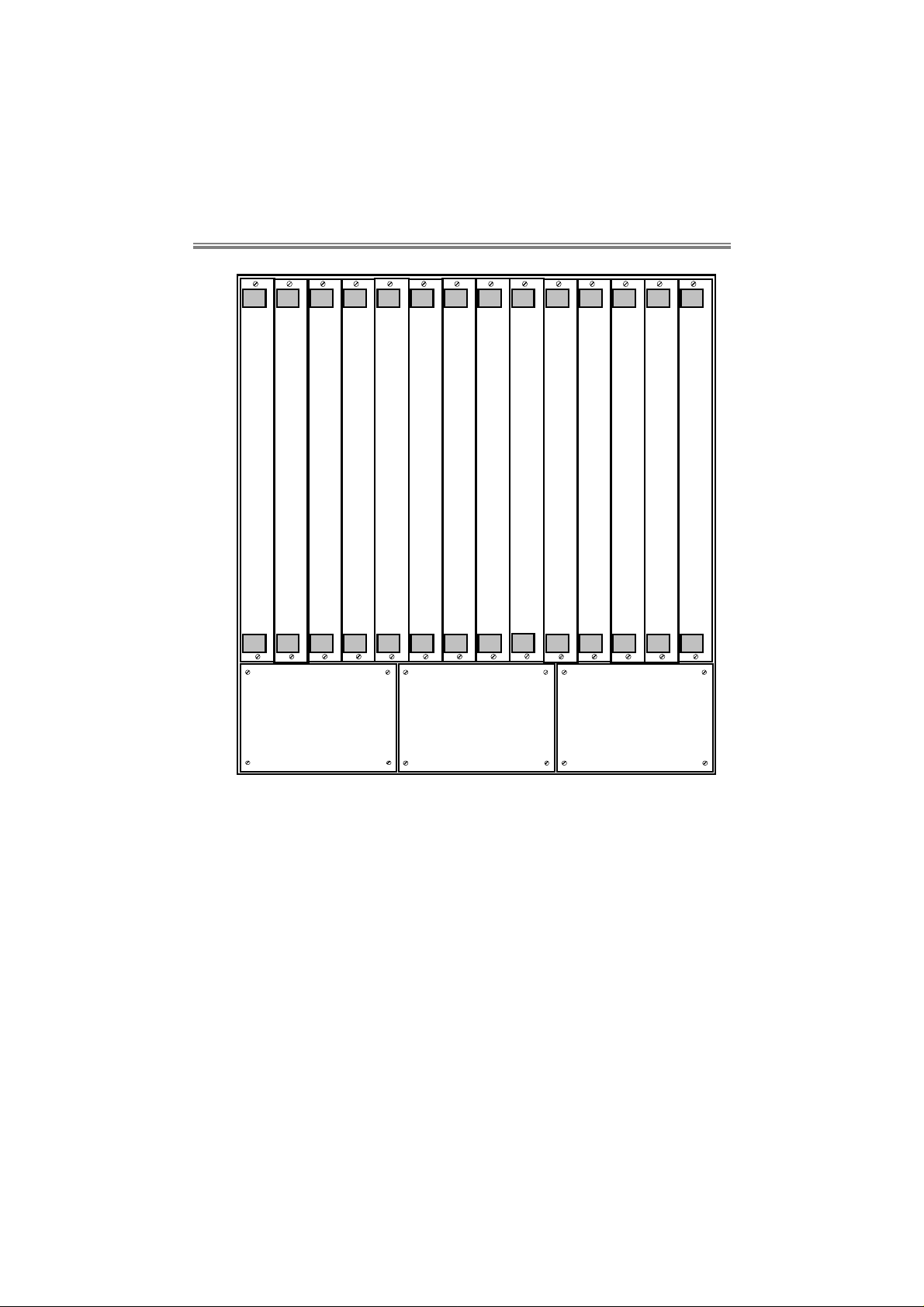
Figure 1.1 The KBU 64 Rackmount Version
Up to 13 KBU 64 card pairs m ay be fitt ed with either one or two power
supplies for resil ience. The 1st c ard slot is f or the Manager Card which
controls all cards within the rack via the KBU 64 polled management
system. If the Manager Card is not fi tt ed, m anagem ent of each c ard can
be perform ed by connecting a ter minal di rectly to t he command por t of
the rear int er face card. When fitted, the manager car d must be placed i n
slot 1, the left-hand most slot of the rack.
Fivemere
80-10100001-091–2

KBU 64 Rackmount Specification
The rackmount version of the KBU 64 is functionally the same as the
standalone in most respects, as it uses the same software. Theref ore
most of the sections of your KBU64 Manual manual (Publication 80-
10100000) relating to KBU 64's operation are relevant.
The rackmount card functionality differs in the following ways:-
• There is a single 15 way command port on each KBU 64 r ear card
for al l com mands and alar ms. T here is no separate alar m port or
alarm rel ay output on the cards. The com m and port has the sam e
function as the standalone 25 way command port.
• The Management Card (if fitted) provides a command port for
access to all KBU 64 cards in the rack.
• Standard physical interfaces are provided for X21 (15 way 'D'),
V35 (34 way MRAC), and V24 (25 way 'D'). Thi s means t hat the
V11/V28 selection links are not provided as they are no longer
necessary. A choice of 3 rear interface cards exist to provide
these interfaces.
• The interf ace LED's are as for the standalone ex cept that the Link
LED's have been omitted for front panel clarity.
• The ISDN cable is connected to the Rear I nterf ace Card by an RJ
45 style plug.
• Power indicati on f or each power supply i s present on the Manager
Card.
80-10100001-09 1–3

Front and Rear Panels and Interfaces
2 Front and Rear Panels and Interfaces
2.1 Front Panel
See the KBU64 standalone manual (Publication 80-10100000) for the
description of operation.
2.2 Rear Interface Cards
Wi th all 3 card types the USER ports are confi gured as physical DCEs,
the LINK ports as DTEs. The USER ports are fem ale and the LINK ar e
male for X21 and V24, both USER and LINK ports are female for V35.
All t hree card types use standard pin connection and so requi re 1 to 1
cables for connection to both user equipment and link equipment.
80-10100001-09 2–1

KBU64 Rackmount
User Manual
USER 1
T 103
R 104
C 108
I 10 7
S 114
115
105
109
BACKUP
USER 2
T 103
R 104
C 108
I 10 7
S 114
115
105
109
BACKUP
B1 IN US E
B1 BACKUP
B2 IN US E
B2 BACKUP
ALAR M 1
ALAR M 2
USER 1
LINK 1
USER 2
LINK 2
COMMA ND
IS D N
USER 1
LINK 1
USER 2
LINK 2
COMMA ND
IS D N
USER 1
LINK 1
USER 2
LINK 2
COMMA ND
IS D N
Front Rear
(X.21)
Figure 2.1 Front and rear Panel Layout
Rear
(V.24)
Rear
(V.35)
80-10100001-092–2

Front and Rear Panels and Interfaces
2.2.1 Link Settings
For all 3 types of Rear I nter f ace Card t he c om m and por t j um per setti ngs
are as follows:
With
Without Manager Card
Link Normal Polled Polled Only
JP8 IN IN X
JP9 OUT OUT X
JP10 OUT IN X
JP11 IN OUT X
JP12 IN IN OUT
JP13 IN IN OUT
JP14 IN IN OUT
Manager
Card
'X' = don't care
80-10100001-09 2–3

KBU64 Rackmount
User Manual
2.2.2 Command Port - KBU 64 Rear Interface Cards
The comm and port on each of t he Rear I nterface Card t ypes i s a f em al e
15 way 'D' type and uses the same V28 lev el circui ts as the standal one
KBU 64. You can onl y use this com mand port when a Manager Card is
not fitted into the rack (please see section 3).
The pin assignments are as follows:
Pin No. Circuit No. Signal Name
1 101 Chassis Earth
2 103 Transmit Data
3 108 Data Terminal Ready
4 104 Receive Data
5 107 Data Set Ready
8 102 Signal Ground/Chassis Earth
10 105 Request to Send
12 109 Data Carrier Detect
15 106 Clear to Send
A standard cable (CAB 0032) can be supplied to present a standar d 25
way interface to the command terminal or PC. This cable has male
connectors at both ends.
80-10100001-092–4

Front and Rear Panels and Interfaces
2.2.3 V35 Rear Interface Card
The User and Link connectors are both 34 way female MRAC.
The pin assignments are as follows:
Pin
Circuit
No.
No.
A 101 Chassis Earth Common return
B 102 Signal Ground/Chassis
P 103A Transmit Data A Generator
S 103B Transmit Data B Generator
R 104A Receive Data A Load
T 104B Receive Data B Load
C 105 Request to Send Generator
D 106 Clear to Send Load
E 107 Data Set Ready Load
H 108 Data Terminal Ready Generator
F 109 Data Carrier Detect Load
Y 114A Transmit Clock A Load
AA 114B Transmit Clock B Load
V 115A Receive Clock A Load
X 115B Receive Clock B Load
Signal Name Assuming configured as
DTE
Common return
Earth
80-10100001-09 2–5

KBU64 Rackmount
User Manual
2.2.4 X21 Rear Interface Card
The User and Link connectors are both 15 way 'D'.
The pin assignments are as follows:
Pin
Circuit
No.
No.
1 Ground Chassis Earth Common return
8 G Signal Ground/Chassis Earth Common return
2 Ta Transmit Data A Generator
9 Tb Transmit Data B Generator
3 Ca Control A Generator
10 Cb Control B Generator
4 Ra Receive Data A Load
11 Rb Receive Data B Load
5 Ia Indicate A Load
12 Ib Indicate B Load
6 Sa Signal Timing A Load
13 Sb Signal Timing B Load
Signal Name Assuming configured as
DTE
2.2.5 V24 Rear Interface Card
The User and Link connectors are both 25 way 'D'.
The pin assignments are as follows:
Pin
Circuit
No.
No.
1 101 Chassis Earth Common return
2 103 Transmit Data Generator
3 104 Receive Data Load
4 105 Request to Send Generator
5 106 Clear to Send Load
6 107 Data Set Ready Load
7 102 Signal Ground/Chassis Earth Common return
8 109 Data Carrier Detect Load
15 114 Transmit Clock Load
17 115 Receive Clock Load
20 108 Data Terminal Ready Generator
Signal Name Assuming configured as
DTE
80-10100001-092–6

Manager Card
3 Manager Card
3.1 Introduction
The KBU 64 Manager Card is a discrete card for use with only
rackmount KBU 64 cards. Like the rackmount KBU 64, the Manager
Card also consists of a car d pair. The rear card provides a command
port for management of all KBU 64 cards within its rack.
The Manager Card must always be fitted in slot 1, the slot on the left
when viewing the rack from the front.
Important
When the manag er Card i s used you cannot use the command port
of any KBU 64 Rear Interface Card. With the Manager Card fitted
you must remove links 12, 13 and 14 on every KBU 64 Rear
Interface Card t o disconn ect the card command in terface. If yo u d o
not do this the signal flow to the Manager Card will be corrupted.
80-10100001-09 3–1

KBU64 Rackmount
User Manual
RXD
TXD
1
OFF
2
OFF
3
OFF
4
OFF
5
OFF
6
OFF
7
OFF
8
OFF
9
OFF
10
OFF
11
OFF
12
OFF
13
OFF
PW R 1
PW R 2
COMMAND
Front
Rear
Figure 3.1 Front and Rear Panels of the Manager Card
80-10100001-093–2

Manager Card
3.2 Front Panel
The front panel of the Manager Card has the following controls and
indicators:
• Tr ansmi t and r ecei v e dat a LED’s f or t he c om m and t erm i nal dat a
lines. These LED’s displ ay data activity on both the transmi t and
receive data circuits.
• AC power indication for each of the power supplies. These
LED’s are fed from the AC power sensing circuits from each
power supply.
• A lock out switch for each of the 13 channels. These are
provi ded to enable the user to set the poll num ber for indiv idual
KBU 64 cards. Once t he cards have been progr am m ed A LL t he
lockout switches must be set to enable the KBU 64s. The
lockout switches can also be used to isol ate a KBU card that i s
streaming unwanted alarms, so allowing other KBU cards to
have access from the Manager Card.
• An LED for each channel to indi cate which channel is activ ely
selected and in com municati on with the Manager Card. W hen
another KBU 64 card i s polled that card's LED will light and the
previously selected card LED will extinguish.
3.3 Rear Panel
The comm and port on Manager Rear Interf ace Car d is a f emal e 25 way
'D' type and uses the same V28 l ev el ci rc uit s and pi n c onnecti ons as t he
standalone KBU 64.
80-10100001-09 3–3

KBU64 Rackmount
The pin assignments are as follows:
Pin No. Circuit No. Signal Name
1 101 Chassis Earth
2 103 Transmit Data
3 104 Receive Data
4 105 Request to Send
5 106 Clear to Send
6 107 Data Set Ready
7 102 Signal Ground/Chassis Earth
8 109 Data Carrier Detect
15 114 Transmit clock
17 115 Receive clock
20 108 Data Terminal Ready
These command ports are PSV4/1 compatible and can therefore be
connected to ext ernal port sharing devices (PSV’s) f or management of
multiple racks of KBU 64s in the same way as the standalone version.
User Manual
80-10100001-093–4

Card Installation
4 Card Installation
Each KBU 64 ‘f ront’ card must be associat ed with an appropri ate (V. 24,
i.e.
X.21, or V.35) rear interf ace car d
pairs (although no damage will result in partial installation)
If the KBU 64s are to be managed individually via their rear panel
command port
connection of the user, li nk, and com mand cables, t he KBU 64s can be
treated in the same manner as standalone KBU 64s for configuration
purposes.
and there is no manager card present
they should always be instal led in
then, after
When i nstalling KBU cards in a rack m ake sure to configure the Rear
Interface Card straps correctly, depending on whether a Manager Car d is
fitted. Refer to KBU64 Manual (Publication 80-10100000) - Link Settings.
4.1 Manager Card Installation
When the KBU 64s are to be managed with a KBU 64 rack manager
card then the manager card must be placed i n slot 1, the slot on the far
left when viewing the rack from the front.
If t he Manager command port i s conected direct to a terminal /PC then
cable CAB0017 or CAB0018 is required (CAB0017 has a female
connector and CAB0018 a male connector at the terminal end). If
connected to a PSV port sharer please contact your Technical Support
for details.
Wi th a direct ly connected t ermi nal it m ay be necessary to f orce CTS or
DCD to the terminal, depending on the terminal’s requirements.
80-10100001-09 4–1

KBU64 Rackmount
User Manual
4.2 Configuration Using a Manager Card
Wi th the Manager Card pair and all KBU card pai rs fi tted t he fi rst task is
to set the individual KBU 64 poll numbers. Once all the units are
installed and a suitable terminal connected to the rack manager card
comm and port, the lockout switches should be set to disabl e access to
all the KBU 64s except one (f or the sake of conv enience it is bett er to
configure the left most KBU 64 f irst). The individual pol l address can
then be set by typing the following commands:-
1> SET POLL xxx[CR]
where xxx represents the unique address in the range 001 to
999
Next, the KBU 64 card needs to be set for polled mode by typing
1> SET CONSOLE POLL[CR]
To check that the KBU 64 is responding, type
1> POLL xxx [CR]
where xxx represents the address that you have just set
The lockout switc h for thi s KBU 64 shoul d then be set to disable the KBU
64 and the next K BU 64 can be progr am m ed by enabl ing via t he l ock out
switches
Once all the KBU 64s have been programmed,
must be set to enable ALL the KBU 64s.
etc. etc.
the lockout switches
80-10100001-094–2

Installation and Power Supply Requirements
5 Installation and Power Supply Requirements
Safety
Warning:
The product is a high densit y rack mount ed unit designed to si t in a 19"
comm unicati ons cabinet, it has four f ix ing poi nts, two down each side of
the front of the frame. All four fixing points must be securely fix the
frame.
The unit i s supplied with a met al fr ont cov er in order to c omply wit h the
European EMC Direc tive. To comply wit h the Direct ive this cov er must
be fitted while the unit is operating.
On the rear of the unit ther e are two IEC m ai ns sockets f or connec ti on to
two independent mains supplies. T he primary eart h connection is made
via these sockets.
Before connecting the mains supply to the
unit check the supply voltage as detailed
below.
Warning - this appliance must be earthed.
Mains cables, 2 metres in length are suppli ed with the unit. T his should
be connected to a suit able mai ns supply. The mai ns plug is the pri mary
disconnect dev ice for the unit. E nsure that the unit is install ed near to a
socket outlet and that the outlet is easily accessible.
The mai ns cables supplied with t he unit i s f it ted wit h a m oulded 13 am p
plug for connecti on to a standard socket outlet . Shoul d t he plug not be of
the correct type for the outlets that it is to be connected to, the plug
80-10100001-09 5–1

KBU64 Rackmount
should be remov ed and the cable re-wired to the correct type of plug.
The use of adaptors is not recommended.
The wires in the supply cord are coloured in accordance with the
following code:-
Green and Yellow Earth
Blue Neutral
Brown Live
As these colours may not correspond with the t ermination's in the plug
being used, it should be connected as follows:The green and yellow wire must be connected to the terminal marked
with the let ter E , or wit h the ear th sym bol , or c olour ed green, or col oured
green and yellow.
The blue wire must be connected t o the termi nal marked with t he letter
N, or coloured black, or coloured blue.
The brown wire must be connect ed to t he term i nal m arked wit h the l ett er
L, or coloured red, or coloured brown.
All dat a com m uni cati ons li nks to t he f ram e shoul d be i n accordanc e wit h
the cable specifications given in KBU 64 Standalone Manual
80-10100000. The rear panel connectors have been fitted with 4-40
screw-locks.
User Manual
The unit can be connected to supplies of the following voltage ranges:a) 97V AC to 132V AC (110 to 120V Nominal)
c) 195V AC to 264V AC (220 to 240V Nominal)
Supply frequencies, in all cases, can be in the range 47Hz to 63Hz.
The max imum power consum ption of the uni t is 125 watts. The current
requirement for each of the voltage ranges is:a) 2A max.
b) 1A max.
Ideal mains inlet fuse rating:
20mm x 5mm, 1.6AH,250V Anti-surge (T) type for 220V to 240V
ratings.
80-10100001-095–2

Installation and Power Supply Requirements
20mm x 5mm, 3.15AH,250V Anti-surge (T) type for 110V to 120V
ratings.
If any problems are encountered with fuses continually blowing the
following alternative ratings maybe used:
20mm x 5mm, 3.15AH,250V Anti-surge (T) type for 220V to 240V
ratings.
20mm x 5mm, 6.3AH,250V Anti-surge (T) type for 110V to 120V
ratings.
Caution — for continued protection against risk of fire, replace
only with same type and rating of fuse.
NOTE:
competent engineer. There are no operator serviceable parts
inside the unit and it should only be opened by a qualified
service engineer. The mains supply should be disconnected
before removing the cover.
The rack should be professionally installed by a
80-10100001-09 5–3

6 Rack Specifications
Rack Specifications
Dimensions
Mains Voltage
Consumption
Frequency
Mains Rear Panel
Fuses
482mm W; 400mm H (9U);
370mm D
93-132V (110-120V nominal)
187-264V (220-240V nominal)
200VA max.
50/60Hz nominal
1.6 or 3.15AH, 250V Anti-Surge
(T) 20x5mm (220-240V range)
3.15 or 6.3AH, 250V Anti-Surge
(T) 20x5mm (110-120V range)
80-10100001-09 6–1

KBU64 Rackmount
User Manual
Environment
Ambient temperature:
Operating 0°C to 30°C
Storage -20°C to 70°C
Atmospheri c pressure: 86.0kPa to
106.0kPa
Relative Humidity: 5% to 95%
non-condensing
80-10100001-096–2

Regulatory Requirements
7 Regulatory Requirements
7.1 United Kingdom and Europe
Users based in the United Kingdom and Europe m ust pay parti cul ar at tent i on
to the information contained in sections 7.1 and 7.2
B.A.B.T. Pan European Approval number AA6046512.
1. The KBU 64 Rackmount is approved for connection to ISDN and X.21
leased circuit services provided by a European Public
Telecommunications Operator.
.
2. Only connect apparatus complying with the requirements of SELV in
accordance with cl ause 2.3 of EN 60 950 t o the por ts on the rear panel of
your unit marked User 1, User 2, Link 1, Link 2, Command and Alarm.
3. Only connect apparatus complying with the requirements of TNV in
accordance with cl ause 6.2 of E N 60 950 to the port on the rear panel of
your unit marked ISDN ‘S’.
7.2 Additional UK Requirements
1. All apparatus connect ed to the user ports and thereby connec ted directl y
or indirectl y to the Briti sh Telecom circui ts must be approved appar atus
as defined in Section 22 of the British Telecommunications Act 1984.
2. The interconnection cables detailed in the KBU64 M anual (Publi c ation 80-
10100000) form part of the approval and cabling itself constitute a
relevant branch system for the digital circuits detailed below.
80-10100001-09 7–1

KBU64 Rackmount
3. The KBU 64 Rackmount is approved for direct connection to the X.21 and
X.21 bis (V.35) or X.21 bis (V.28) Kilostream provided by British
Telecom PLC or any similar service provided by other British
Telecommunications operators, or a relevant branch system for those
digital circuits which accord to CCITT recommendations X.21 and X.21
bis.
Where connection is made to circuits conforming to CCITT, X21
bis, Service Categories 1 and 2 are supported.
For Serv ice Category 1, data rates of 2.4 kbit/s to 19.2 kbit/s are
avai lable and connecti on is vi a an integral cable term inated wit h a
25 way D-Type connector conforming to BS 6623: Part 1: 1985.
For Serv i ce Category 2, data rates of 48k , 56k and 64k bit /s m ay be
used. Connection is vi a an integral cabl e terminat ed with a 34 pin
connector conforming to BS 6623: Part 1: 1986.
4. If any other apparatus, including cabling or wiring is to be connected
between the apparatus, and the point of connection to the di gital ci rcuits
detailed in above, then all that other apparatus shall conform to the
following:
a) The overall transmission characteristics of all that other apparatus
shall be such as to introduce no material effect upon the electrical
conditions presented to one another by the apparatus and the digital
circuit.
User Manual
b) All the other apparatus shall comprise only:
i) apparatus approved (see note) for the purpose of connection
between the apparatus and the digital circuit, and;
ii) cable or wiring complying with a code of practice for the
installation of apparatus covered by this standard
or such other requirements as may be applicable.
Note: Such apparatus may have been approved subject to
limitations on its use.
80-10100001-097–2
 Loading...