

Page 1
i
CONTIN UI TY TESTER
AND FIXTURE
MODEL 128/PC
Page 2

Page 3

Model 128/PC Instruction Manual Page iii
February 25, 2005
MODEL 128/PC
INSTRUCTION MANUAL
(Part Number 5900389)
Cablescan
A Eubanks Company
3022 Inland Empire Blvd.
Ontario, California 91764
(909) 483-2436 Fax (909) 483-2463
www.cablescan.com
Page 4

Page iv Model 128/PC Instruction Manual
COPYRIGHT NOTICE
This manual is proprietary, copyrighted material. No part of this manual may be reproduced or
transmitted in any form or by any means, electronic or mechanical, including photocopying and
recording, for any purpose other than the purchaser's personal use, without written permission of
Cablescan Inc.
Copyright © 1996 - 2005 Cablescan Inc. All rights reserved.
THIS IS A LIMITED WARRANTY
CABLESCAN (hereinafter “CABLESCAN”) products are warranted to the original owner for a
period of twelve (12) months from the date of shipment from CABLESCAN’s factory, or in the
first 2,080 hours of operation by the customer (whichever comes first), to be free from defects in
material and workmanship for the use for which they are intended by CABLESCAN, under
normal operating conditions and maintenance.
CABLESCAN’s obligation under this Warranty is limited, upon prompt notification, to the
repair or exchange at the CABLECAN factory of any CABLESCAN product or part which
proves to be defective. If a product under warranty is returned to the CABLESCAN factory for
repair or replacement, freight charges will be borne by the customer in accordance with
CABLECAN’s policy of selling F.O.B. the CABLESCAN factory. If repairs are made at the
customer’s factory, the customer will bear the cost of the service person’s travel and living
expenses.
THIS WARRANTY IS EXPRESSLY IN LIEU OF ALL OTHER WARRANTIES EXPRESSED
OR IMPLIED. THERE ARE NO IMPLIED WARRANTIES OF MERCHANTABILITY OR
FITNESS FOR A PARTICULAR PURPOSE. THIS WARRANTY STATES CABLESCAN’S
ENTIRE AND EXCLUSIVE LIABILITY WHETHER IN TORT OR IN CONTRACT AND
BUYER’S EXCLUSIVE REMEDY FOR ANY CLAIM FOR DAMAGES IN CONNECTION
WITH THE SALE OR USE OF CABLESCAN’S PRODUCTS, THEIR DESIGN,
SUITABILITY FOR USE, INSTALLATION OR OPERATION, OR FOR ANY CLAIMED
DEFECTS THEREIN. UNDER NO CIRCUMSTANCES WILL CABLESCAN BE LIABLE
FOR ANY CONSEQUENTIAL, INCIDENTAL, ECONOMIC, DIRECT, INDIRECT,
GENERAL, OR SPECIAL DAMAGES. NO ACTION UNDER THIS WARRANTY MAY BE
BROUGHT BY BUYER MORE THAN ONE YEAR AFTER THE CAUSE OF ACTION HAS
OCCURRED.
This warranty does not apply to equipment or replacement parts that have not been given proper
care and maintenance and does not cover any defect, failure, deficiency, or error that is:
a) Not reported to Cablescan within the applicable warranty period;
b) Due to accident, misapplication, negligence, modification, alteration, disassembly, abuse,
misuse, abnormal conditions of temperature, dirt, or corrosive matter; or
c) Due to operation, either intentional or otherwise, above rated capacities, or in an
otherwise improper manner.
If it is determined that the equipment defect is not the result of original manufacture but is
related to customer negligence or operational error, the customer will pay all incurred charges
including, but not limited to, parts and labor.
Page 5

Model 128/PC Instruction Manual Page v
TABLE OF CONTENTS
Specifications.............................................................................................. viii
System Overview............................................................................................1
The Model 128/PC.....................................................................................................1
Major Features............................................................................................................1
Front Panel Controls and Display ..............................................................................2
Display Format...........................................................................................................3
Rear Panel Layout......................................................................................................3
Interface Fixture.........................................................................................................4
Signature Codes..........................................................................................................4
Program Storage.........................................................................................................5
User Labels.................................................................................................................6
Quick Start.....................................................................................................7
Tester Setup................................................................................................................7
Adapter Card Installation...........................................................................................7
Learn Cable Assembly...............................................................................................7
Test Cable Assembly..................................................................................................7
Program Storage.........................................................................................................8
Simplified Instructions..................................................................................9
Operating Instructions................................................................................14
Front Panel Modes ...................................................................................................14
Learn...............................................................................................................14
Search.............................................................................................................15
Error List........................................................................................................16
Test..................................................................................................................17
Reset................................................................................................................18
Menu-selected Modes and Functions.......................................................................19
Save Program .................................................................................................19
Load Program.................................................................................................20
Delete Program ..............................................................................................21
Clear Memory.................................................................................................22
Set Baud Rate..................................................................................................22
Print Wire List ................................................................................................23
Print User List ................................................................................................24
Loop Test ........................................................................................................25
Self Test...........................................................................................................26
Page 6

Page vi Model 128/PC Instruction Manual
TABLE OF CONTENTS- CONTINUED
PC Keyboard Operating Instructions .......................................................27
Introduction..............................................................................................................27
Entering Commands.................................................................................................27
Test Commands........................................................................................................27
Print Commands.......................................................................................................28
Program Commands.................................................................................................28
System Setup ................................................................................................30
Unpacking ................................................................................................................30
Initial Setup..............................................................................................................30
Power Turn-On and Self Test...................................................................................30
Return of Faulty Unit ...............................................................................................31
Printer Setup.............................................................................................................31
PC Interface..............................................................................................................33
Changing Power Setting...........................................................................................34
Remote Output Signals ...............................................................................36
Adapter Cards..............................................................................................37
Selection...................................................................................................................37
Installation................................................................................................................37
Custom Adapter Cards.............................................................................................37
Setting Adapter Codes..............................................................................................39
Adapter Card List.....................................................................................................40
Care of the Model 128/PC...........................................................................43
Maintenance.............................................................................................................43
Repair.......................................................................................................................43
Memory Backup Battery..........................................................................................43
Replacement Parts....................................................................................................43
Page 7

Model 128/PC Instruction Manual Page vii
LIST OF FIGURES
Figure Description Page
1 Front Panel Controls and Display............................................................................2
2 Rear Panel Layout....................................................................................................3
3 Interface Fixture.......................................................................................................4
4 Program Storage - Accommodations and Use.........................................................5
5 Simplified Self-programming (LEARN) Procedure................................................9
6 Simplified Test Procedure .....................................................................................10
7 Simplified Wire Identification (SEARCH) Procedure ..........................................11
8 Simplified Save Program Procedure......................................................................12
9 Simplified Load Program Procedure .....................................................................13
10 Sample Error List Printouts ...................................................................................16
11 Sample Wire List Printouts....................................................................................23
12 Sample User List Printout......................................................................................24
13 Power Switch and Jumper Locations.....................................................................35
14 Schematic - Model 128 CPU/Scanner Board ........................................................44
Page 8

Page viii Model 128/PC Instruction Manual
SPECIFICATIONS
TEST POINT CAPACITY
128 points, 64 points per connector
OPERATING SPEED
Test: < 0.5 sec.; Self Test: < 2 sec.; Learn: < 0.5 sec.
TEST PARAMETERS
Short Threshold: < 100 Ohms
Open Threshold: > 1000 Ohms
Continuity Threshold: < 100 Ohms
Test Current: < 3 milliamps
Body Current: < 5 microamps
TEST VOLTAGE
10 VDC, max.
INTERWIRE CAPACITANCE
.01 microfarad, max.
DISPLAY
16-character Alphanumeric LCD
PROGRAM STORAGE
Battery-backed CMOS RAM containing a test program area and 112 stored program locations
without User Labels, or 28 program locations with User Labels.
BATTERY LIFE
5 years
POWER REQUIREMENTS (INTERNALLY SELECTABLE)
104 to 126 VRMS, 50/60 Hz or
208 to 252 VRMS, 50/60 Hz
TEMPERATURE
Operating: 32 to 105 °F (0 to 40 °C)
Storage: -40 to 165 °F (-40 to 74 °C)
DIMENSIONS
13.75 x 11.25 x 3.5 in. (34.4 x 28.6 x 8.9 cm)
WEIGHT
7.0 lbs. (3.2 kg)
Page 9

Model 128/PC Instruction Manual Page 1
SYSTEM OVERVIEW
THE MODEL 128/PC
The Cablescan Model 128/PC is a microprocessor-based continuity tester with a built-in
interface fixture. It tests for both opens and shorts from one point to all other points in cables
and harnesses of up to 128 connections. Testing is programmed by the Learn method or by
programs downloaded from a PC. Up to 112 programs may be stored in memory for future use.
The built-in interface fixture enables testing of a wide variety of connector types and sizes, using
Cablescan's library of test adapter cards. Circuit types that can be tested include flat ribbon
cables, discrete wiring harnesses, and those having jumpers, daisy chains, open contacts, and
other interconnect devices.
An RS-232C interface accommodates either an optional printer, or a personal computer (PC).
MAJOR FEATURES
Major features and functions of the Model 128/PC are as follows:
• Self programming by "learning" a "known good" or sample harness from a batch.
• Programming by downloading from a PC.
• Automatic test of each cable or harness to be tested, and display of error locations.
• Built-in interface fixture for quick and inexpensive connection of test cable.
• Program save and load.
• Identification or location of wires through touch, using wrist strap or probe.
• Self test of the Model 128/PC.
• Alphanumeric test point labels (user labels).
• Memory for 112 wire list programs (without user labels) or 28 programs (with user
labels).
Optional features are:
• Printout of wire list learned during self programming.
• Printout of errors encountered during test.
• Control by PC with Cablescan TERM software.
Page 10
Page 2 Model 128/PC Instruction Manual
FRONT PANEL CONTROLS AND DISPLAY
The Model 128/PC employs a 16-digit alphanumeric backlighted LCD (Liquid Crystal Display).
The display provides the user with test conditions, signature codes, adapter codes, and error
information.
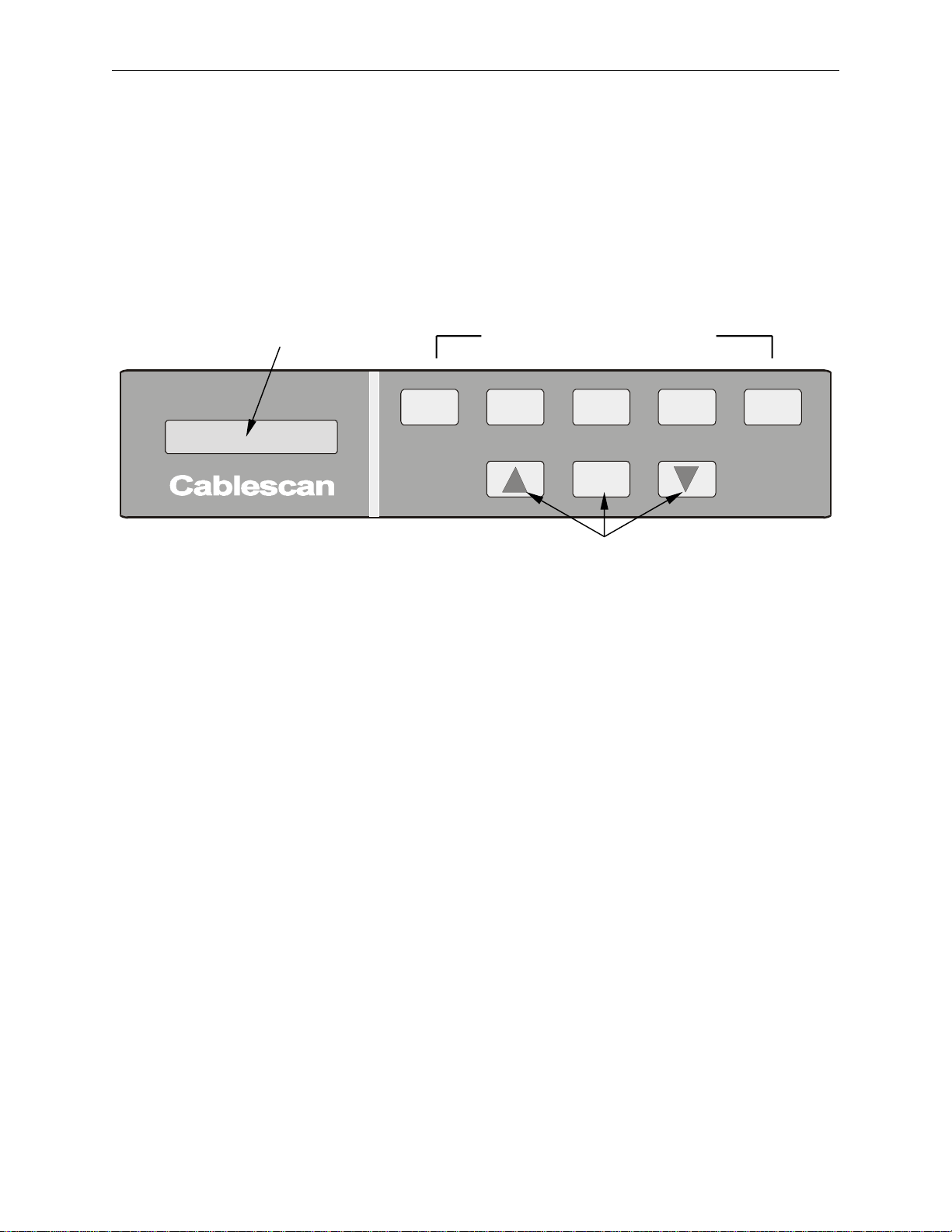
All modes and functions of the Model 128/PC are controlled by keys on the front panel. Six
modes are selected by individual keys, and nine menu modes and functions are selected through
Up and Down keys and executed by the Menu Run key. See Figure 1, below.
LCD Display Front Panel Mode Keys
MODEL 128
LEARN SEAR CH
ERROR
LIST
MENU
RUN
TEST
RESET
Menu-select Keys
LEARN
- Initiates a scan on a known-good cable (harness assembly, ribbon cable,
etc.), and stores the resultant wire list data in the Test Memory. A 4-digit
signature code is calculated based on the wire list stored in memory and the
adapters cards installed, and it is displayed for program identification.
SEARCH
- Initiates a continuous scan of the adapter card connectors and displays each
point that is touched with the wrist strap or probe. (See Figure 2 for
location of the probe input.)
ERROR LIST
- Initiates a test on a connected cable assembly and produces a printout of
errors, or prints "Passed" if no errors.
Initiates a continuous test of the connected cable and displays errors, or
TEST
displays "Passed" if no errors.
RESET
MENU RUN
UP/DOWN
ARROWS
Terminates current mode and places Model 128/PC in "wait" state until next
mode selection is made.
Initiates the menu mode selected and currently displayed. Also used to
advance a menu mode and to respond “yes” to a menu prompt.
Used for stepping up and down through menu to select one of nine available
functions or modes. (Refer to Menu-selected Modes and Functions in the
Operating Instructions section.) .
Also steps through Program Memory to select wire list to load
-
Figure 1. Front Panel Controls and Display
Page 11
Model 128/PC Instruction Manual Page 3
DISPLAY FORMAT
The Model 128/PC has 128 test points, which are divided between two adapter card locations;
side A and side B, with 64 test points on each side. When displaying from/to information during
test, an A or a B prefix is attached to the pin number to identify the connector. Therefore, an
open between pin 5 on A side and pin 10 on B side is displayed as:
O A-05 B-10.
The relationship between test point and adapter card connector/pin numbers is provided in the
table below:
Description Left Side Right Side
Adapter Connector Side A Side B
Adapter Pin # 1 to 64 1 to 64
Test Point # 1-64 65 to 128
Displayed Connector/Pin # A-01 to A-64 B-01 to B-64
NOTE
User labels (Test point labels) can be programmed to replace the
displays A-01 through B-64. This requires a PC for programming the
labels in a text editor and then downloading the labels to the tester
using an optional software program.
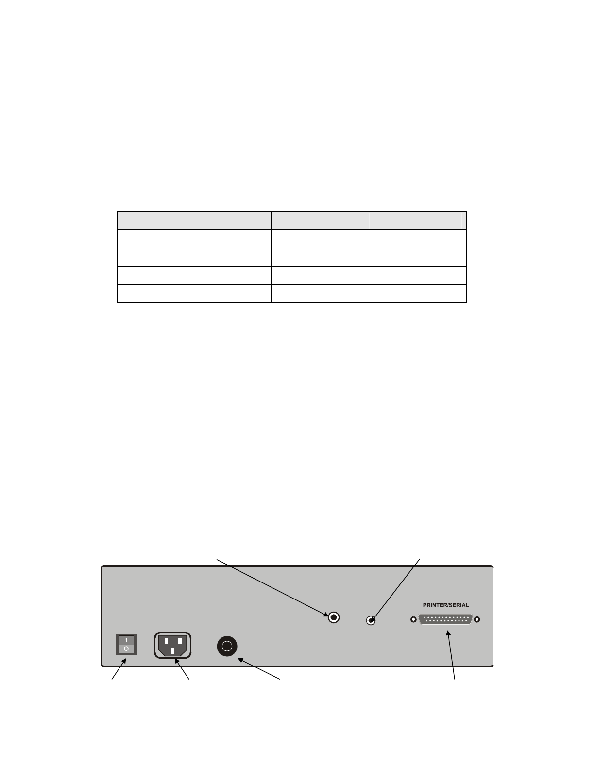
REAR PANEL LAYOUT
The rear panel contains a power switch; an AC receptacle for line power connection; a power
fuse; Probe connector for either a probe or wrist strap, an Enable receptacle; a serial port
connector for a printer or personal computer (PC).
A wrist-strap kit provides the capability to locate wires during troubleshooting through body
conductance, using either a probe provided in the kit, or touch by fingers.
An optional 80-column serial printer provides hard copies of error lists, wire lists, and user label
lists. Refer to Printer Setup instructions in the System Setup section.
Probe/Wrist Strap Learn/Save Enable
PROBE
250mA/250V
S
E
U
F
F
E
S
U
F
CAUTION!
U
S
E
For continued protection against
risk of fire, replace only with
same type and rating of fuse.
Power Switch AC Receptacle Power Fuse PC/Printer Interface
ENABLE
Figure 2. Rear Panel Layout
Page 12
Page 4 Model 128/PC Instruction Manual
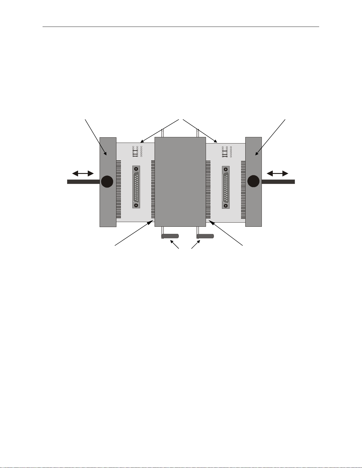
INTERFACE FIXTURE
The interface fixture (Figure 3) has cam-operated ZIF connectors for easy exchange of adapter
cards, and rapid connection and disconnection of cable assemblies being tested. Information on
Cablescan adapter cards and configurations is provided in the Adapter Cards section. Cards are
replaced by simply lifting the ZIF levers and sliding the cards up
A SIDE B SIDE
Adjustable Adapters Adjustable
Hold-down Bar Cards Hold-down Bar
23456
1
111 2
8910
7
23456
1
111 2
8910
7
A-01/Pin #1 (Top) ZIF Levers B-01/Pin #65 (Top
Figure 3. Interface Fixture
SIGNATURE CODES
The Model 128/PC is designed for the use of signature codes in achieving harness identification,
tracebility, and configuration control, as follows:
• When the first harness (usually a "known good") of a specific part number is run through
the Learn mode, the Model 128/PC calculates and displays a four-digit signature code
unique to the cable wiring configuration and the adapters used.
• If a printer is connected, that signature code are included on the wire list printout.
• Whether in hard copy (printout) form, or recorded manually, the signature code is paired
up with the part number for that harness, and kept on file for identification of future
batches.
• Every time a batch of the same part number is to be tested, a random sample of that
batch is run through Learn for self programming, and the displayed signature code must
match the signature code on file.
• Since the Model 128/PC can also store multiple wire list programs in memory, the
signature is used in identifying the wire list program when loading from memory.
• Signature codes eliminate the need to assign names to wire lists for identification.
Page 13
Model 128/PC Instruction Manual Page 5
PROGRAM STORAGE
The Model 128/PC has memory accommodations either for 112 wire list programs without user
labels or for 28 programs with User Labels, as well as a Test Memory location for the wire list
currently in use (see Figure 4).
A program may be loaded into the Test Memory from any one of the 112/28 Program Memory
locations, and the program in the Test Memory may be moved to a Program Memory location.
These modes and functions are accomplished through four of the Menu-selected modes. (Refer
to Menu-selected Modes and Functions.) Signature codes are used to identify wire lists in
Program Memory for loading and for identifying the wire list currently in Test Memory.
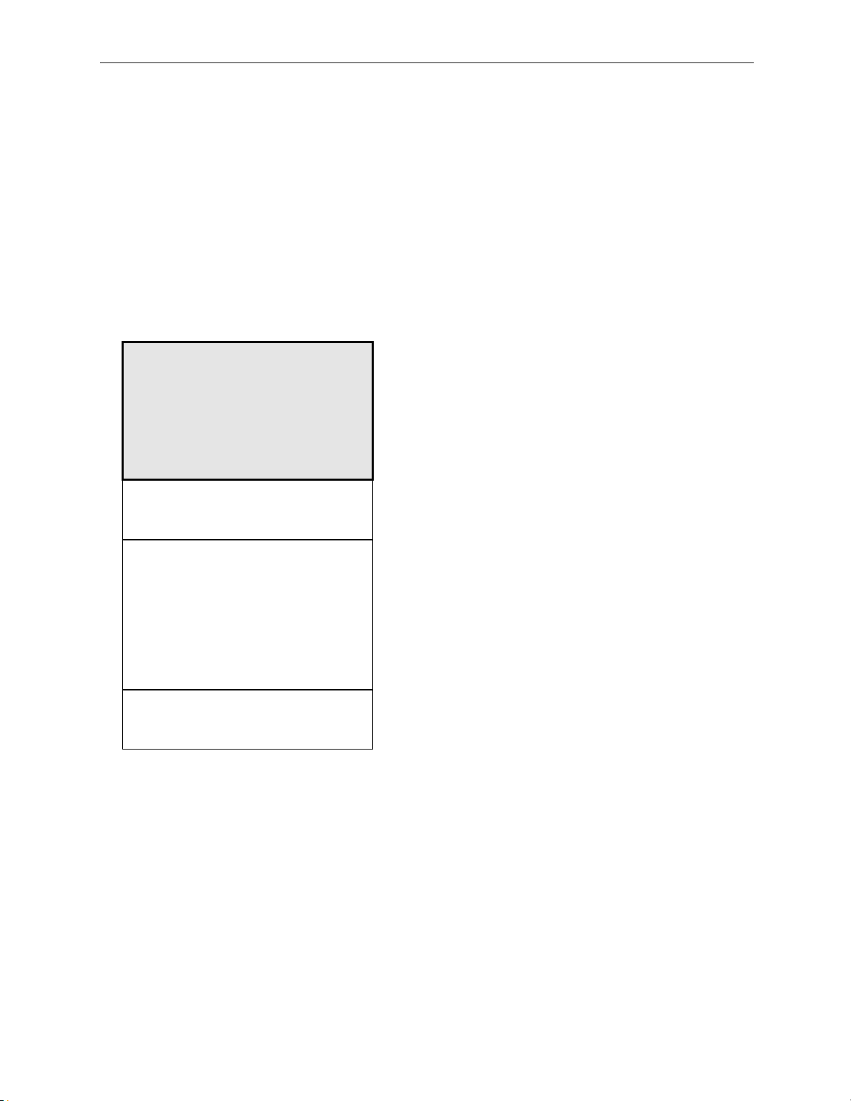
TEST MEMORY LOCATION
PROGRAM #1
PROGRAM #2
PROGRAM #112
Each program with a user label occupies 4 Program Memory locations.
• Create test program in Test Memory during
Learn procedure. (Program may also be
downloaded through the RS-232C
Printer/Serial port into Test Memory.)
• To store a newly created program for future
use, copy it to Program Memory using the
Save Program function (Menu-selected).
• All tests are run from Test Memory. To use a
program that is stored in Program Memory,
copy it into the Test Memory using the Load
Program function (Menu-selected).
• All programs remain in Program Memory.
Save Program and Load Program functions
only copy them to and from Test Memory.
Programs are eliminated only by using the
Delete Program function (Menu-selected).
The Clear Memory mode (Menu-selected) is
used to erase wire lists from the Test Memory
only.
NOTE
Figure 4. Program Storage - Accommodations and Use
Page 14

Page 6 Model 128/PC Instruction Manual
USER LABELS
The Model 128/PC does not have a built-in user label or wire list editor. Programming of user
labels, as well as programming wire lists without learning a wire list, is performed with a PC and
Cablescan’s optional MS DOS-based software program, TERM. TERM provides keyboard
control over the Model 128/PC through the printer/serial port. The TERM program is basically a
terminal emulation program that allows keyboard entry and control over the tester. The program
also has features to allow wire lists and user labels to be transferred to and from the Model
128/PC.
Six-character user labels can be assigned to test points for each wire list program stored in the
Model 128/PC. Since testing on the Model 128/PC using adapter cards is typically limited to
two-ended cables, user labels are not generally necessary. User labels are more useful when the
Model 128/PC is interfaced to a harness board or external fixture. These applications usually
have more than two connectors and, therefore, locating specific connector/pin locations using the
standard display of the Model 128/PC is more difficult since the display refers to side A and side
B connectors. When user labels are assigned to test points, all displays and printouts will show
user labels in lieu of the A and B connector identification on the interface fixture. Once user
labels are assigned, connector/pin locations are displayed between the actual connector and pin
numbers on the wire harness. This eliminates the need to have a separate translation chart cross
referencing the test points to the actual harness connector/pin numbers.
Page 15

Model 128/PC Instruction Manual Page 7
QUICK START
Ordinarily, the setup and operation of the Model 128/PC requires a thorough understanding of
this manual. This section, however, is provided for situations where immediate use is required.
When using this procedure, refer to the sections indicated within the procedure when more detail
is required for specific steps.
TESTER SETUP
Refer to the System Setup section for details.
1. Remove Model 128/PC from shipping container and set on suitable work station.
2. Connect line cord between rear panel and a properly grounded outlet. (See Figure 2.)
3. Turn power on by moving switch on rear panel to 1 (on). A Ready message will display
and a short tone will sound.
4. Press Down arrow to step through menu modes until Self Test is displayed.
5. Press MENU RUN to initiate Self Test. Passed Self Test will display.
ADAPTER CARD INSTALLATION
Refer to the Adapter Cards section for details.
1. Select cable assembly to be tested and match an adapter card to each end of the cable.
2. Open ZIF connector levers, slide adapter cards in from the top and all the way laterally
into their respective connectors. Each adapter card is designed to fit only the right or left
side.
3. Close ZIF connectors and install the cable to be tested between A and B adapter cards.
LEARN CABLE ASSEMBLY
Refer to Learn mode in the Operating Instructions section for details.
1. Press RESET, and then press LEARN.
2. A 4-digit signature will display after learn is complete. (See Signature Codes in System
Overview.)
TEST CABLE ASSEMBLY
1. Press RESET, and then TEST. The cable is good when Passed is displayed. Tests are
continuously run until the cable is removed.
2. Remove the cable from the adapter cards. (As soon as the cable is removed, an open
circuit will display.)
3. Test the remaining cables.
Page 16

Page 8 Model 128/PC Instruction Manual
PROGRAM STORAGE
Refer to Save Program (menu-selected) in the Operating Instructions section for details.
1. The 4-digit signature code is used to identify wire list programs in memory. Record the
signature code for the cable assembly. (Refer to Signature Codes in System Overview
section.)
2. Insert the supplied microphone plug into Enable jack on rear panel.
3. Press RESET, and then arrow down to step through the menu until Save Program is
displayed.
4. Press MENU RUN to initiate Save Program. (Refer to Save Program in Operating
Instructions section.) After the program is saved, the display will show "Saved
XXXXXX," where XXXXXX is the signature code of the program.
Page 17
Model 128/PC Instruction Manual Page 9
SIMPLIFIED INSTRUCTIONS
The Cablescan Model 128/PC Continuity Tester is simple and easy to use. As with any
microprocessor-based device, however, the user first should become familiar with its features
and functions, how to operate it, and how to care for it. After becoming properly acquainted
with the Model 128/PC, the user can refer to the abbreviated procedures illustrated in Figures 5
through 9. Detailed procedures are provided in the Operating Instructions section.
2 3, 6 2
MODEL 128
23 45 6
7 8 9 101112
1
LEARN SEARCH
ERROR
LIST
MENU
RUN
23 45 6
7 8 9 101112
1
TEST
RESET
4 5 1
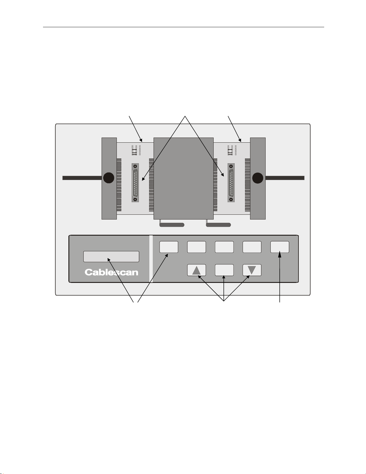
1. Press RESET.
2. Install appropriate adapter cards for the cable to be tested.
3. Install sample, or known-good cable or harness assembly.
4. Press LEARN. Signature code will display after Learn is complete.
5. Select and Print Wire List from the menu, or record signature code manually.
6. Remove sample, or known-good cable or harness assembly.
Figure 5. Simplified Self-programming (LEARN) Procedure
Page 18
Page 10 Model 128/PC Instruction Manual
2 3, 5 2
MODEL 128
23 45 6
7 8 9 101112
1
LEARN SEARCH
ERROR
LIST
MENU
RUN
23 45 6
7 8 9 101112
1
TEST
RESET
4 5b 4, 5a 1
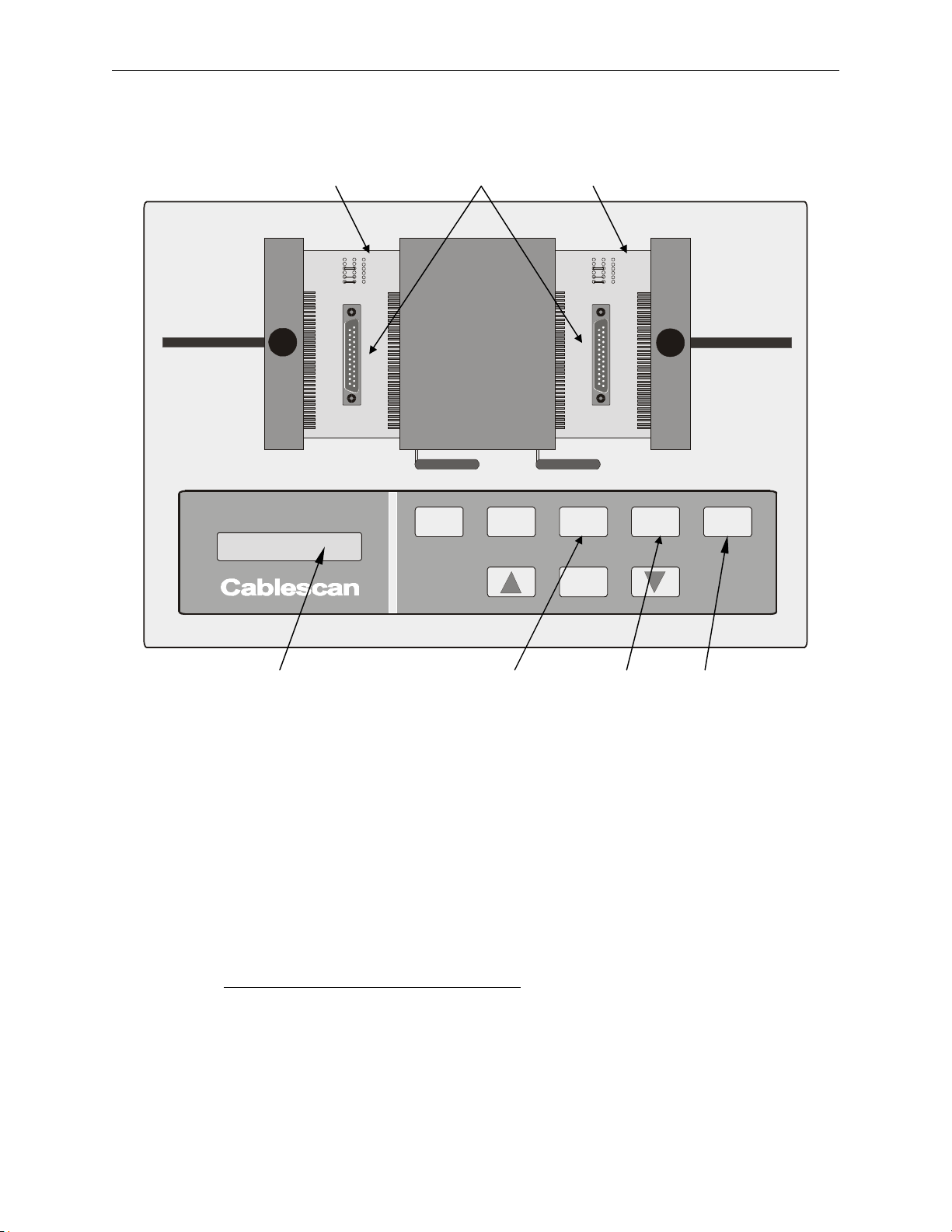
1. Press RESET.
2. Install appropriate adapter cards for the cable to be tested.
3. Install cable or harness to be tested.
4. Press TEST; observe Passed on Display.
5. Remove tested cable or harness, and install the next cable to be tested.
If Failure Encountered (Open or Short):
5a) Repair fault, or press TEST again to view additional errors.
5b) To get a hardcopy of the errors, press RESET, and then ERROR LIST.
Figure 6. Simplified Test Procedure
Page 19
Model 128/PC Instruction Manual Page 11
3
250mA/250V
S
E
U
F
F
U
E
S
S
E
U
F
CAUTION!
PROBE
For continued protection against
risk of fire, replace only with
same type and rating of fuse.
ENABLE
2
23456
1
7 8 9 101112
23456
1
7 8 9 101112
MODEL 128
LEARN SEARCH
ERROR
LIST
MENU
RUN
TEST
RESET
4 1
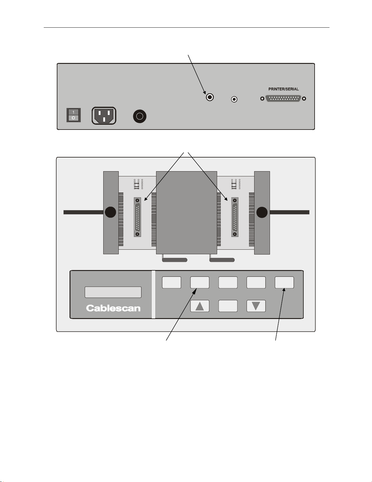
1. Press RESET.
2. Install appropriate adapter cards for the cable to be tested
3. Connect wrist strap or probe to Probe receptacle.
4. Press SEARCH.
5. Touch wire end with fingers or probe. Pin numbers will be displayed. Repeat for each
wire or circuit point to be identified.
Figure 7. Simplified Wire Identification (SEARCH) Procedure
Page 20
Page 12 Model 128/PC Instruction Manual
2
MODEL 128
250mA/250V
S
E
U
F
F
U
E
S
S
E
U
F
23 45 6
7 8 9 101112
1
CAUTION!
LEARN SEARCH
PROBE
For continued protection against
risk of fire, replace only with
same type and rating of fuse.
ENABLE
ERROR
LIST
23 45 6
7 8 9 101112
1
TEST
RESET
MENU
RUN
4, 7 3, 6 1, 5
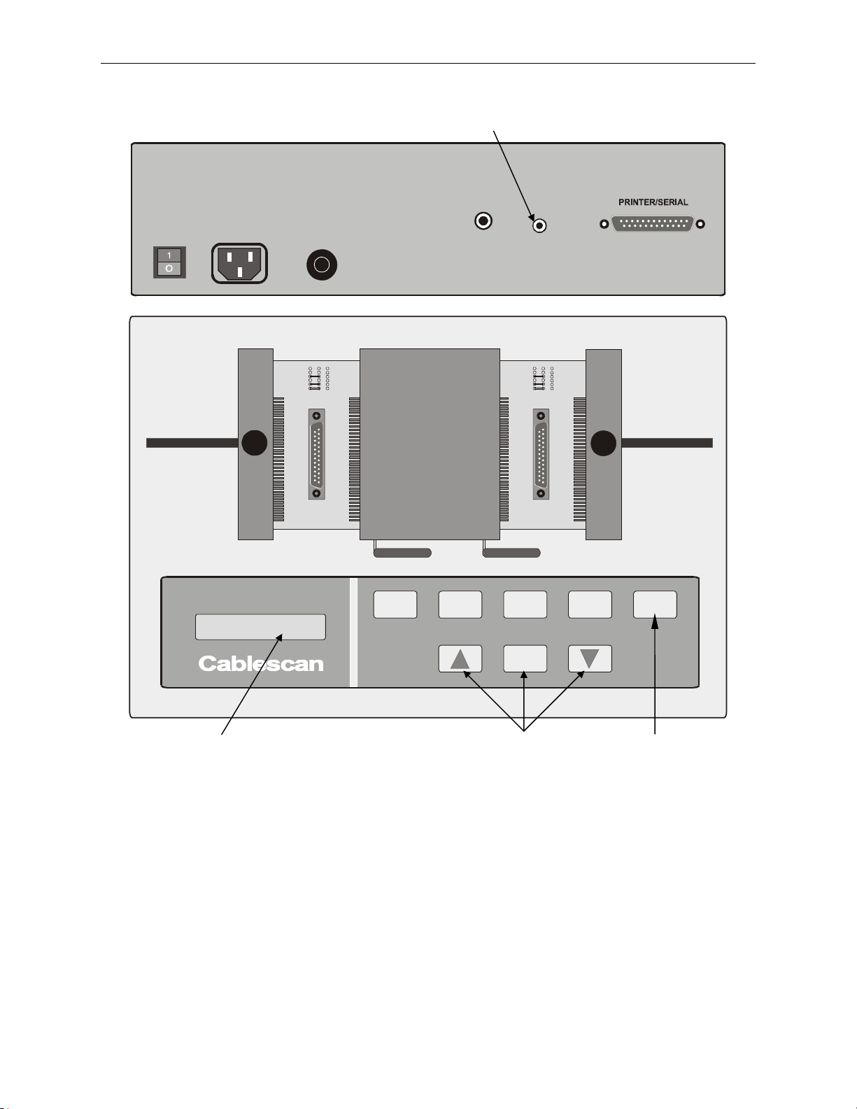
1. Press RESET.
2. Engage Enable plug on rear panel.
3. Select and initiate Save Program.
4. The display will read Are You Sure?
5. If it is decided not to save the program, press RESET.
6. To save the program, press MENU RUN. The program will be copied from the Test
Memory into a Program Memory location.
7. After the program is saved, the display will show SAVED XXXXXX, where XXXXXX
is the signature code of the program.
Figure 8. Simplified Save Program Procedure
Page 21
Model 128/PC Instruction Manual Page 13
MODEL 128
23456
1
7 8 9 101112
LEARN SEARCH
ERROR
LIST
MENU
RUN
23456
1
7 8 9 101112
TEST
RESET
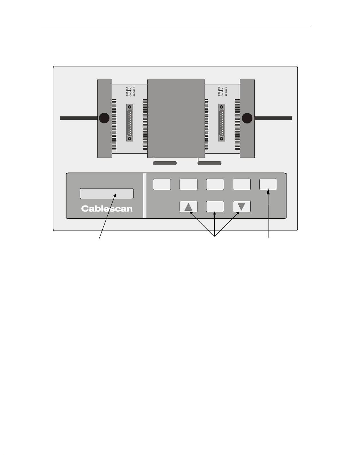
3, 4, 7 2, 4, 6 1, 5
1. Press RESET.
2. Select and initiate Load Program.
3. The display will show a signature code of a program stored in Program Memory.
4. Use Up/Down arrows to step to the signature code for the desired program, as shown in
the display.
5. If it is decided not to load the program, press RESET.
6. Press MENU RUN to load the program into the Test Memory.
7. Verify signature code on display against the code recorded for the cable assembly to be
tested.
Figure 9. Simplified Load Program Procedure
Page 22
Page 14 Model 128/PC Instruction Manual
OPERATING INSTRUCTIONS
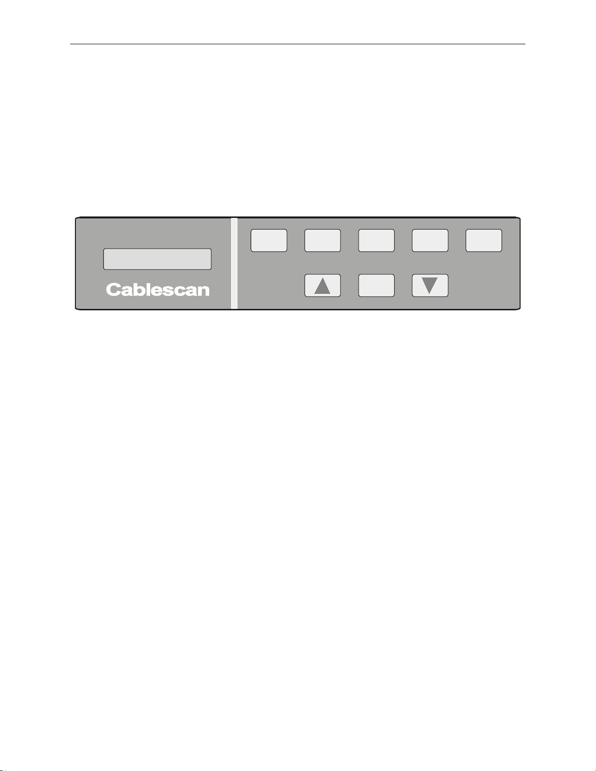
FRONT PANEL MODES
The following detailed procedures are provided for acquainting the new user with the front panel
modes and functions of the Model 128/PC. All modes and functions are selected and controlled
by keys on the front panel. Five modes are controlled by individual keys across the top of the
panel. Three keys across the bottom are provided to control nine modes and functions from a
menu.
MODEL 128
LEARN SEAR CH
ERROR
LIST
MENU
RUN
TEST
RESET
Learn
Before testing, it is necessary to prepare a program for the harness to be tested, unless a program
already exists. This is done through the Learn mode. A complete programming procedure,
using a known-good harness, is provided below. Once familiarized, however, the user may need
only refer to Figure 5.
1. Select and install a pair of adapter cards (Adapter Cards section) for the cable assembly
to be tested.
2. Mate each connector on the cable assembly to the appropriate adapter card.
3. Press LEARN. The Model 128/PC instantly scans the cable assembly, stores its
configuration (wire list) in Test Memory, and calculates a signature code for that
configuration. The display will show:
Learned (Signature code #)
4. If printer is connected, select and initiate Print Wire List from the menu. Notice that the
printout also will contain the signature code shown on the display. Refer to the Print
Wire List procedure later in this section.
5. Retain the wire list for future use in identifying the program just created. If no printout is
made, record the displayed signature code for future use.
6. Follow Save Program function to save wire list program in Program Memory.
7. Disconnect learned harness from Model 128/PC.
Page 23

Model 128/PC Instruction Manual Page 15
NOTE
The Learn mode and the signature code can be used in lieu of saving the
program in Program Memory. Learning a cable assembly each time from a
batch, and comparing the signature code with the recorded one eliminates the
need to save the program and then load it from memory each time a batch of
cables requires testing. However, if the preferred procedure is to save the
program and load it for testing a new batch, refer to the Save Program and
Load Program procedures later in this section.
Search
Search mode enables use of a wrist strap or probe as an aid in identifying wires or circuit points.
Each point contacted will be displayed in succession. To select and use the SEARCH mode,
proceed as follows:
1. Press RESET.
2. Select and install a pair of adapter cards for the cable assembly to be probed.
3. Mate each connector on the cable assembly to the appropriate adapter card.
4. Insert wrist strap or probe lead into Probe jack on rear panel (see Figure 2).
5. Fasten strap around one wrist, or grasp probe.
6. Press SEARCH.
7. Touch wire end with hand or probe, and the display will show the pin number(s) of that
wire.
8. Touch another wire, and its corresponding pin number(s) will be displayed.
NOTE
If more than one wire is touched at a time, or if the wire touched
is connected to others, the display will scroll through the
numbers in succession.
Page 24

Page 16 Model 128/PC Instruction Manual
Error List
This mode requires hookup of the optional printer. When ERROR LIST is selected, it performs
a single test and prints a list of errors encountered, or it prints Passed when there are no errors.
Sample error lists using adapter connector numbers and user labels are shown in Figure 10. To
select and use ERROR LIST, proceed as follows:
1. Press RESET.
2. Select and install a pair of adapter cards for the cable assembly to be tested.
3. Mate each connector on the cable assembly to the appropriate adapter card.
4. Verify printer is connected. (Refer to Printer Setup in System Setup section.)
5. Load program to be used. (Refer to "Load Program" later in this section).
6. Press ERROR LIST. The Model 128/PC performs a single test and prints a list of all
errors, or prints Passed if there are no errors.
7. When test and printout are finished, disconnect harness.
Adapters A: 05 B: 06 Signature: 1066
------------------------------------------------ Error List
Condition From Point To Point
------------------------------------------------OPEN A 3 B 12
SHORT A 3 B 10
OPEN A 1 B 10
SHORT A 8 B 12
OPEN A 8 B 16
Failed
(Error list without user labels)
Adapters A: 05 B: 06 Signature: 1066
-----------------------------------------------
Error List
Condition From Point To Point
-----------------------------------------------
OPEN J1-3 P1-3
SHORT J1-3 P1-1
OPEN J1-1 P1-1
SHORT J1-8 P1-3
OPEN J1-8 E2
Failed
(Error list with user labels)
Figure 10. Sample Error List Printouts
Page 25

Model 128/PC Instruction Manual Page 17
Test
When TEST mode is selected, the Model 128/PC continuously scans all points of the cable
assembly, using the wire list program in Test Memory as a comparison. The wire list program
can be created using the Learn mode, or it can be loaded from Program Memory if previously
learned and saved. Refer to the Learn mode or the Load Program function in this section. A
complete Test procedure is provided below. Once familiarized, however, the user may refer to
Figure 6. To select and use TEST, proceed as follows:
1. Press RESET.
2. Select and install a pair of adapter cards for the cable assembly to be tested.
3. Mate each connector on the cable assembly to the appropriate adapter card.
4. Press TEST. If the harness passes the test, "Passed" will display, and a tone will sound.
5. Remove the passed cable, and connect next cable to be tested. Test will automatically
resume.
NOTE
For subsequent harnesses of the same configuration, it is not
necessary to press TEST for each harness. Upon insertion of
each new harness, TEST automatically continues.
FAULTY CABLE ASSEMBLY
If an open, short, or miswire has been detected, an O (for Open) or an S (for Short or
Miswire) will display at the far left of the display, and the two point numbers (From
and To points) will display to the right of the error type as follows.
O A-03 B-03
If a failure is between points on the same side of the adapter card, the display will
show:
S A-04 A-05
4. To continue the test, either correct the error, or press TEST. If an error was corrected,
and no other errors are detected, a Passed will display after all circuits have been
retested. If the error was not corrected, and TEST was pressed to resume testing, the test
scan will cycle through and back to the original error, unless another error is detected, in
which case that error will be displayed.
5. If the printer is connected, press ERROR LIST to obtain a printout of failures.
A sample Error List Printout is shown in Figure 10.
6. Remove harness and connect the next cable assembly to be tested.
Page 26

Page 18 Model 128/PC Instruction Manual
Reset
The RESET mode is available for terminating any mode currently in operation. Pressing RESET
is required with some modes that display an end message upon completion. When RESET is
pressed, the display alternates between displaying the signature code of the wire list in Test
Memory and one of the menu modes.
Page 27
Model 128/PC Instruction Manual Page 19
MENU-SELECTED MODES AND FUNCTIONS
The nine menu-selected modes and functions are as follows:
Save Program * Self Test
Load Program Loop Test
Delete Program * Set Baud Rate *
Clear Memory * Print Wire List
Print User List
* Requires the Enable jack to operate.
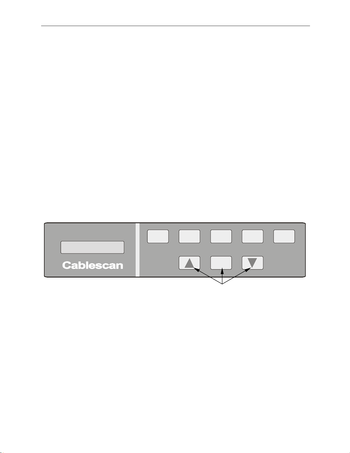
These menu-selectable modes and functions are accessed through the MENU RUN key and the
Up and Down arrow keys. To select one of the menu modes or functions, use the following
standard procedure:
1. Press Up or Down arrow to step through the menu until the desired function or mode is
displayed.
2. Insert the Enable plug if the mode, in the above list, ends with an asterisk (*).
3. Press MENU RUN to initiate the function or mode.
MODEL 128
LEARN SEAR CH
ERROR
LIST
MENU
RUN
TEST
RESET
Menu-select Keys (3)
Save Program
The Save Program function is used to copy the program from the Test Memory to the Program
Memory. A complete Save Program procedure is provided below. Once familiarized, however,
the user may refer to Figure 8. To select and use the Save Program function, proceed as follows:
1. Insert Enable jack in the rear panel. (See Figure 2.)
2. Press the Up or Down arrow to step through the menu to display Save Program.
3. Press MENU RUN to initiate the save function. If there is sufficient Program Memory
for the program, the display will query:
Are You Sure?
Page 28

Page 20 Model 128/PC Instruction Manual
4. Press MENU RUN again to save the program. After the program has been saved, the
display will show:
Saved (signature #)
5. If you decide not to save the program, press RESET instead of MENU RUN.
6. If there is insufficient Program Memory to save the program, the display will show:
MEMORY FULL
7. Evaluate the programs currently saved to determine if any are no longer needed. Refer to
the Delete Program procedure to make room in memory for new programs. (Remember,
a wire list with user labels occupies 4 memory locations.)
8. Rerun the above Save Program procedure after programs have been deleted.
Load Program
The Load Program function is used to copy one of the stored programs (in Program Memory) to
the Test Memory. The program in Test Memory will be over-written by the program being
loaded.
If the program in Test Memory is to be retained for future use, first save it by means of the Save
Program function before performing this procedure.
A complete Load Program procedure is provided below. Once familiarized, however, the user
may refer to Figure 9. To select and use the Load Program function, proceed as follows:
1. Press Up or Down arrow to step through the menu to display Load Program. (Enable
jack not required for loading programs.)
2. Press MENU RUN to initiate Load Program, and the display will show the signature for
the last program that was selected with the Load or Delete function:
Load Program (signature #)
3. Press Up or Down arrow until the display shows the signature for the program to be
loaded into Test Memory. (Each time the arrow is pressed, the next program signature
will display.) A Bottom of List message will appear after all programs have been
displayed using the Down arrow. A Top of List message will appear after all programs
have been displayed using the Up arrow.
4. If it is decided not to load the program, press RESET.
5. When the desired program signature is reached, press MENU RUN and the program will
be copied into the Test Memory.
Page 29

Model 128/PC Instruction Manual Page 21
Delete Program
The Delete Program function is used to erase a program from Program Memory. (It does not
affect the program currently in Test Memory.)
A complete Delete Program procedure is provided below. To select and use the Delete Program
function, proceed as follows:
1. Insert Enable jack in the rear panel. (See Figure 2.)
2. Press Up or Down arrow to step through the menu to display Delete Program.
3. Press MENU RUN to initiate the mode, and the display will show the signature for the
last program that was selected with the load or delete function:
Delete Program (signature #)
4. Press Up or Down arrow until the display shows the signature for the program to be
deleted. (Each time the arrow is pressed, the next program signature will display.) A
Bottom of List message will appear after all programs have been displayed using the
Down arrow. A Top of List message will appear after all programs have been displayed
using the Up arrow.
5. If you decide not to delete a program, press RESET.
6. Press MENU RUN to delete the program for the displayed signature, the display will
query:
Are You Sure?
7. Press MENU RUN a second time to delete the program. After the program has been
deleted, the display will show:
Deleted (signature #)
Page 30

Page 22 Model 128/PC Instruction Manual
Clear Memory
This mode is required for clearing the Test Memory of the wire list and user labels before
running the Learn mode. (The wire list in test memory is automatically deleted when Learn is
initiated.) If user labels are in the Test Memory along with the Test program, the labels will be
attached to the test points for the new program generated with the Learn mode. Clearing
memory before Learn will prevent labels from being attached to the new program. Clear
Memory must first be enabled by the Enable jack on the rear panel. To initiate and use Clear
Memory, proceed as follows:
1. Engage Enable jack on the rear panel. (See Figure 2.)
2. Press Up or Down arrow to step through the menu until Clear Memory is displayed.
3. Press MENU RUN key to initiate Clear Memory. The display will show:
CLEAR MEMORY?
4. If you selected Clear Memory in error, or otherwise have decided not to use it, press
RESET to exit the mode. If you do wish to clear the Test Memory, press MENU RUN
key a second time, and the memory will be cleared. The display will now show:
Memory Cleared
A cleared test memory will display a signature code of “0000.”
Set Baud Rate
The Model 128/PC has two baud rate settings: 1200 and 9600. The 1200 baud rate is used for
printing. The 9600 baud rate is used when interfacing the serial port to a PC. The Set Baud Rate
function must first be enabled by the Enable jack on the rear panel. To initiate and use Set Baud
Rate, proceed as follows:
1. Engage Enable jack on the rear panel. (See Figure 2.)
2. Press Up or Down arrow to step through the menu until Set Baud Rate is displayed.
3. Press MENU RUN key to initiate the mode. The display will show one of the following
as the current setting:
Baud Rate 1200
or
Baud Rate 9600
4. To change the baud rate, press the Up or Down arrow. The baud rate will change
between 1200 and 9600.
5. Press MENU RUN or RESET when the desired baud rate is displayed. The display will
show:
Completed
Page 31

Model 128/PC Instruction Manual Page 23
Print Wire List
This mode requires hookup of the optional printer. A wire list printout provides a hardcopy of
the test program in Test Memory. The wire list printout also includes the program signature for
future reference. To select and run Print Wire List, proceed as follows:
1. Verify that a serial printer is connected and is “on line.” Refer to Printer Setup in the
System Setup section.
2. Press Up or Down arrow to step through the menu to display Print Wire List.
3. Press MENU RUN to initiate printing. The printout will show the test program in Test
Memory. Sample wire lists are shown below.
Adapters A: 05 B: 06 Signature: 1066
-------------------------------------------------
Wire List
Sequence From Point To Point
-------------------------------------------------
001 A-05 B-13
002 A-04 B-14
003 A-03 B-12
004 A-02 B-11
005 A-01 B-10
006 A-09 B-15
007 A-08 B-16
End of List
(Wire list with user labels)
Adapters A: 05 B: 06 Signature: 1066
-----------------------------------------------
Wire List
Sequence From Point To Point
-----------------------------------------------
001 J1-5 P1-4
002 J1-4 P1-5
003 J1-3 P1-3
004 J1-2 P1-2
005 J1-1 P1-1
006 J1-9 E1
007 J1-8 E2
End of List
(Wire list with user labels)
Figure 11. Sample Wire List Printouts
Page 32

Page 24 Model 128/PC Instruction Manual
Print User List
This mode requires hookup of the optional printer. A user list printout provides a hardcopy of
the user labels and wire list signature currently loaded in Test Memory. To select and run Print
User List, proceed as follows:
1. Verify that a serial printer has been connected, according to the Printer Setup procedure
in the System Setup section.
2. Press Up or Down arrow to step through the menu to display Print User List.
3. Press MENU RUN to initiate printing. A sample user list is shown below.
Adapters A: 05 B: 06 Signature: 1066
-----------------------------------------------
User List
001 J1-1
002 J1-2
003 J1-3
004 J1-4
005 J1-5
006 J1-6
007 J1-7
008 J1-8
009 J1-9
010 P1-1
011 P1-2
012 P1-3
013 P1-4
014 P1-5
015 E1
016 E2
End of List
Figure 12. Sample User List Printout
Page 33

Model 128/PC Instruction Manual Page 25
Loop Test
Executing the Loop Test mode will initiate continuous scanning of the cable assembly, useful for
locating intermittent connections. When an error is encountered, the test is halted and the error
is displayed. The error will remain on display until MENU RUN is pressed to continue. This
mode differs from the Test mode. The Test mode automatically continues the test when the error
is removed, whereas, the Loop Test remains halted, displaying the error, even if the error is no
longer present. A complete Loop Test procedure is provided below. To select and use Loop
Test, proceed as follows:
1. Press RESET.
2. Select and install a pair of adapter cards for the cable assembly to be tested.
3. Mate connectors on the cable assembly to the appropriate adapter cards.
4. Load wire list to be used in this test (refer to Load Program), or learn the wire list using
the Learn procedure.
5. Press Up or Down arrow to step through the menu until Loop Test is displayed.
6. Press MENU RUN to initiate the Loop Test mode. Each time a successful scan is
completed, a loop count on the display is incremented by one as shown below:
Loop #001
7. An O for open or S for short, with the From/To points, will be displayed when an error is
encountered. A short between test point 63 on adapter card A (A-63), and 32 on adapter
card B (B-32), will be displayed as follows:
S A-63 B-32
8. To restart the test, press MENU RUN, and the loop counter will reset to zero; or to
continue through the current cycle to locate additional errors, press TEST.
9. Press RESET when testing is complete.
Page 34

Page 26 Model 128/PC Instruction Manual
Self Test
This mode is used to verify the test points within the Model 128/PC. Basically it checks for
opens and shorts on the scanner transmit and receive lines. When an error is located, the error
type (Open or Short) and the faulty points are displayed. No test harness may be connected to
the unit during Self Test; connections between test points caused by the cable assembly will
result in failing Self Test. Performing a Self Test while the adapter cards are connected will
result in the cards also being tested for shorts. If shorts are displayed, however, remove the cards
and rerun the Self Test to isolate the problem to either the cards, or the tester. A complete Self
Test procedure is provided below. To select and use Self Test, proceed as follows:
1. Press RESET and remove the cable assembly, if connected.
2. Press Up or Down arrow to step through the menu until Self Test is displayed.
3. Press MENU RUN to initiate Self Test. During the start of Self Test the display will
show the part number of the PROM (software) of the Model 128/PC as follows:
PROM #340XXXX
Where 340XXXX is the current version of software in the Model 128/PC.
4. After the test is complete, with no errors displayed, Passed Self Test will display.
5. If an error is located, testing stops and the error is displayed. To continue past the error,
press MENU RUN again.
6. If the adapter cards are installed and the Self Test failed, remove the adapter cards and
rerun Self Test.
7. If the tester fails without the adapter cards installed, verify that the ZIF connectors are
free of debris.
8. Clean the ZIF connectors with isopropyl alcohol and a brush
9. After cleaning, rerun Self Test.
10. If the Model 128/PC fails Self Test with no adapter cards, and the ZIF connectors have
been cleaned, contact Cablescan for repair.
Page 35

Model 128/PC Instruction Manual Page 27
PC KEYBOARD OPERATING INSTRUCTIONS
INTRODUCTION
The Model 128/PC can be controlled from a PC keyboard instead of the front panel controls.
Keyboard control can be added by interfacing to a personal computer (PC) that is running
Cablescan’s Terminal Emulation Software, TERM. Refer to the System Setup section for setting
up a PC. Using the PC keyboard, the operator can execute most functions available through the
front panel mode keys and Menu selections.
The PC also allows the operator to view 24 lines of information on the monitor instead of just the
single line on the front panel display.
ENTERING COMMANDS
Commands are entered at the system prompt. To get the prompt, press the ESC key on the
keyboard. All commands are two letters that are executed by pressing their two keys, followed
by an ENTER.
There are three categories of commands, as shown below:
• Test - test-related commands that allow a single or continuous test to be run, self test of
the tester, and pin number identification.
• Print - used to obtain a hardcopy of test programs and test results.
• Program - used to load, save, and maintain programs in memory.
TEST COMMANDS
The following commands are used in the testing for opens and shorts, self testing of the Model
128/PC, and identifying test points. These are two-letter commands, which are executed by
pressing the two letter keys, followed with an ENTER.
Scan Test - SC
Same as TEST button on Front Panel. A continuous test is executed on the cable assembly under
test, and each error (open or short) is displayed. After each error is displayed, testing may be
continued by pressing ENTER. Passed is displayed on the monitor after each successful test.
Loop Test - CT
Same as Loop Test selected from the Menu. A loop count of the number of passed tests is
displayed on the monitor.
Self Test - TT
Same as Self Test selected from the Menu. Displays software version of Model 128/PC, and
displays test results on the monitor.
Page 36

Page 28 Model 128/PC Instruction Manual
Search - SB
Same as SEARCH key on the front panel. Displays the test points or user label assignments on
the monitor as points are probed.
PRINT COMMANDS
The following list contains all print-related commands. The printout will appear on the monitor
during printing since the PC uses the same port as the printer. Output will pause after displaying
20 lines. If there are additional lines, MORE will display at the end of each full screen.
Pressing ENTER will continue the output. At the system prompt, enter the two-letter command,
followed by an ENTER.
Print Wire List - PW
Same as Print Wire List selected from the front panel Menu.
Print Error List - PE
Same as ERROR LIST key on the front panel.
Print User Labels List - PU
Same as Print User List selected from Menu.
PROGRAM COMMANDS
The following list contains commands related to loading, saving, and deleting wire list programs.
These are two-letter commands, which are executed by pressing the two letter keys followed
with an ENTER.
Clear Memory - CM
This command is the same as Clear Memory selected from the Menu. When the prompt Are you
sure? is displayed, pressing the letter Y will erase the program and User Labels in Test Memory.
If you decide not to clear memory, press the letter N.
Delete Program - DI
This command is the same as Delete Program selected from the Menu. Delete Program is used
to erase a wire list program in the Program Memory. When the DI command is typed, followed
by an ENTER, the signature of one of the programs in memory is displayed. Pressing the letter
D advances down through the list displaying the next program signature. Pressing the letter U
displays the signature in the reverse order. When the signature of the program to be deletes is
displayed, press ENTER. The prompt prompt Are you sure? is then displayed. Pressing the
letter Y will erase the program. If you decide not to erase the program, press the letter N.
Page 37

Model 128/PC Instruction Manual Page 29
Learn - LG
This command is the same as the LEARN key on the front panel. It is used to create a wire list
program automatically by scanning a connected harness assembly and storing the continuities in
the Test Memory. The learned program overwrites the program that is in the Test Memory. If
the program in the Test Memory has not been saved and is to be used later, use the Save Program
command before running Learn.
Load Program - LI
This command is the same as Load Program selected from the Menu. Use the Load Program
command to load a stored program from the Program Memory into the Test Memory. When the
LI command is typed followed by an ENTER, the signature of one of the programs in memory is
displayed. Press the letter D to advance down the list of programs, or press the letter U to
advance up the list. The next program signature will display each time the letter is pressed. To
load the program corresponding to the displayed signature, press ENTER.
Save Program - SI
This command is the same as Save Program selected from the Menu. The Save Program
command is used to copy the program currently in the Test Memory into the Program Memory.
If there is insufficient Program Memory to store the wire list, Memory Full is displayed. If
there is sufficient Program Memory, prompt Are you sure? is displayed. To save the program,
press the letter Y.
Page 38

Page 30 Model 128/PC Instruction Manual
SYSTEM SETUP
UNPACKING
Upon unpacking the Model 128/PC from its shipping carton, inspect it for evidence of abuse
during shipment. If such is found, notify Cablescan and the carrier at once. Save the shipping
carton and packing materials for later use.
INITIAL SETUP
When shipped from the factory, the Model 128/PC is set for operating from one of the following
power sources:
104 to 126 VRMS at 50/60 HZ.
208 to 252 VRMS at 50/60 HZ.
The line power cord receptacle on the rear panel (Figure 2) is labeled for one of the above
voltage settings.
1. Be sure that the source voltage and Model 128/PC are of the same rating before
connecting the power cord. If they are not, refer to "Changing Power Settings."
2. Make sure that the power switch on the back panel is set to 0 (off), and then plug in the
power cord.
3. Turn power switch to 1 (on), and observe that a message is displayed. The Model
128/PC is ready for use. (If nothing happens, check power source, power cord
connections, and the fuse on the rear panel.)
POWER TURN-ON AND SELF TEST
Verify that the power cord is connected to the proper power source, as described under the initial
hookup, then proceed as follows:
1. Turn power on at the unit by moving the power switch on the rear panel to 1 (ON); the
display will light up with a message and the tone will sound.
2. For self test of the basic Model 128/PC, verify that no cable assembly is connected and
adapter cards are not installed.
3. Press the Up or Down arrow to step through the menu to reach Self Test.
4. Press MENU RUN to initiate Self Test. If the unit passes its self test, the display will
show Self Test Passed, and a tone will sound; if it fails, the display will show one of the
following:
O for open, plus the internal connector pin number.
S for short, plus the internal connector pin numbers.
5. The self test will stop if an error is encountered. To resume the test, press MENU RUN
again.
Page 39
Model 128/PC Instruction Manual Page 31
RETURN OF FAULTY UNIT
If a unit should fail self test upon delivery, notify Cablescan immediately.
PRINTER SETUP
An RS-232C PRINTER/SERIAL port is provided on the rear panel (Figure 2) to accommodate
an 80-column serial printer.
1. Prepare printer for use and connect it to its proper power source, in accordance with the
instruction manual supplied with the printer.
2. Connect printer interface cable to the PRINTER/SERIAL connector on the rear panel of
Model 128/PC.
3. On the printer, turn printer switch ON, and verify that the printer SELECT light is on.
4. Set Model 128/PC power switch to 1 (on).
5. Press the Up or Down arrow to step through the menu to reach Set Baud Rate.
6. Press MENU RUN to initiate setting the baud rate.
7. If the display reads "Baud Rate 1200," press RESET to continue.
8. If the display shows: "Baud Rate 9600," press the Down arrow to change to 1200 and
then press MENU RUN.
Data Format
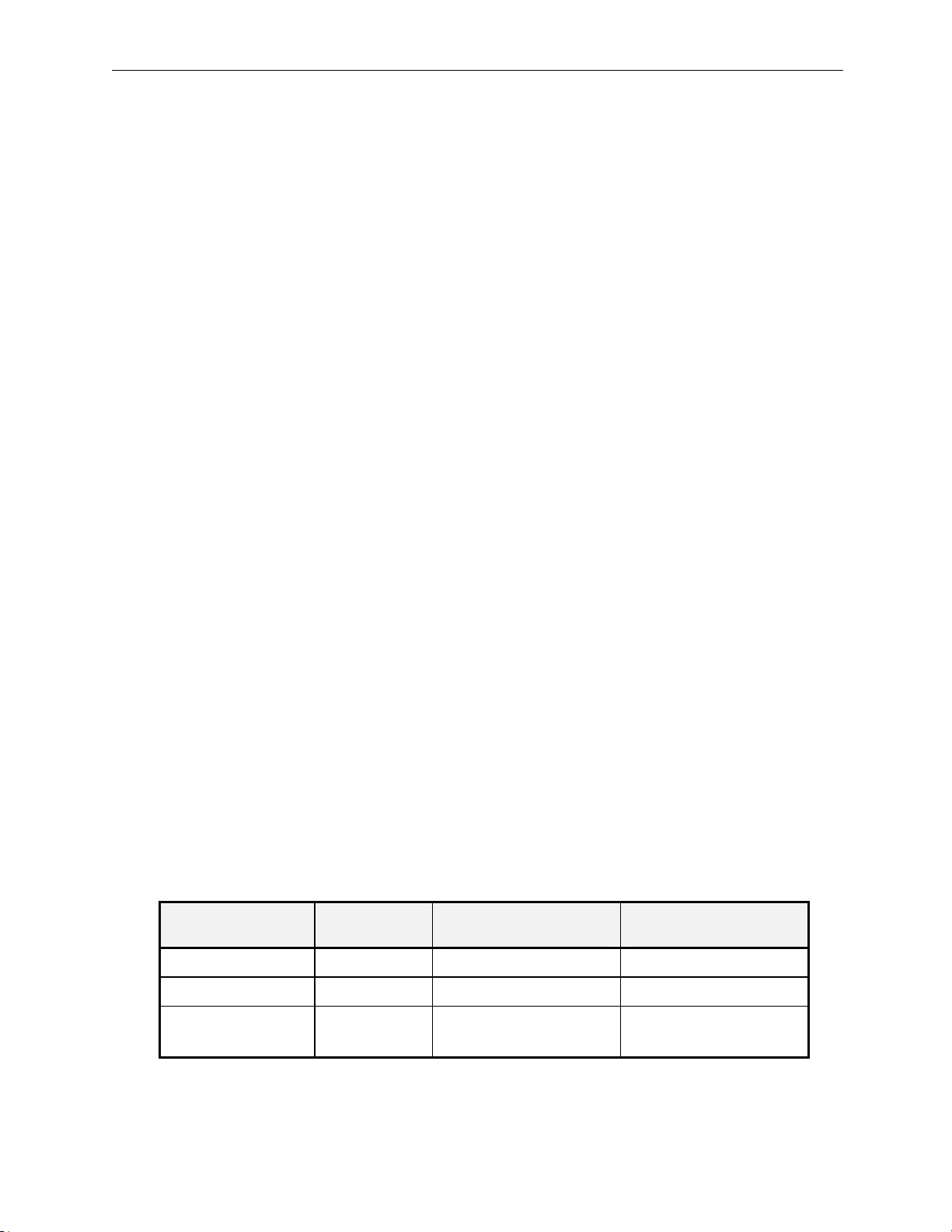
If the printer was not provided by Cablescan, the following setup data are required:
Transmission to the printer is at 1200 Baud, with 8 data bits, 1 stop bit, and no parity.
Printer Cable
The printer connector on the Model 128/PC is also used for external control signals that are not
printer related. Therefore, a fully loaded 25-pin printer cable should not be used. The pin
assignments for the printer are as follows:
Description Symbol
Receive Data RD 3 3
Tester
25-Pin ‘D’
Printer
25-Pin ‘D’
Signal Ground SG 7 7
Supervisory
Send Data
SSG 11 11
(Printer Cable P/N 5210791)
Page 40

Page 32 Model 128/PC Instruction Manual
NOTE
Pin #11 is used to indicate when the printer is ready to receive data. In Okidata
printers, the signal name is "Supervisory Send Data"; it may also be referred to
as "Printer Busy." The printer sets this signal HIGH to indicate the print
buffer is full and to stop sending data. A different pin number and signal must
be substituted for printers without this signal. Also, the polarity of the signal
must be correct (busy when HIGH) or selectable by an internal switch in the
printer.
Printer Troubleshooting
Perform the following steps if the printer does not print after being set up according to the above
procedure.
1. Verify printer has serial capability. Printers use 25-pin D connectors for serial
communications and 36-pin ribbon connectors for parallel communications. Some
printer manufacturers offer serial printers as an option only.
2. Verify printer is on and Select light or On Line light is ON.
3. Verify that the cable is wired with the pin assignments shown above.
4. Turn power off and then on after making switch changes on the printer. This causes the
printer to read the new switch settings.
5. Verify in the printer manual that pin 11 is used by the printer to control data and the
polarity is correct.
6. If tester stays in the printing mode, the polarity of SSD could be incorrect. Disconnect
pin 11 and verify printing.
7. If data is printed at random but most of the data is correct, the data control signal into pin
11 of the tester is incorrect. Refer to printer manual.
8. Verify that both the printer and the tester baud rates are set to 1200.
Page 41
Model 128/PC Instruction Manual Page 33
PC INTERFACE
The RS-232C PRINTER/SERIAL port on the rear panel can be used to connect a Personal
Computer (PC) when a printer is not connected. Cablescan provides an optional MS DOS based
software program (TERM), which can be used to control and transfer programs between the
Model 128/PC and the PC. The software also can be used to transfer programs between the
Model 128/PC and other Cablescan testers.
1. Install the TERM software program in your PC in accordance with the software
instruction manual.
2. Connect an interface cable between the serial port (male D-type connector) on the PC and
the 25-pin female D-type connector on the rear panel of the Model 128/PC labeled
PRINTER/SERIAL.
3. Set Model 128/PC power switch to 1 (on).
4. Press the Up or Down arrow to step through the menu to reach Set Baud Rate.
5. Press MENU RUN to initiate setting the baud rate.
6. If the display reads Baud Rate 9600, press RESET.
7. If the display shows: Baud Rate 1200, press the Down arrow to change to 9600, and then
press MENU RUN.
8. Execute TERM from the DOS prompt on the PC.
9. A greater-than prompt (>) should appear on the PC screen.
NOTE
If the prompt does not appear, press ESC. Also verify that the
interface cable is wired according to the pin assignments shown
below and verify the correct baud rate of 9600. The software
automatically sets the communications format and baud rate on
the PC. The serial port on the PC must also be set for COM1.
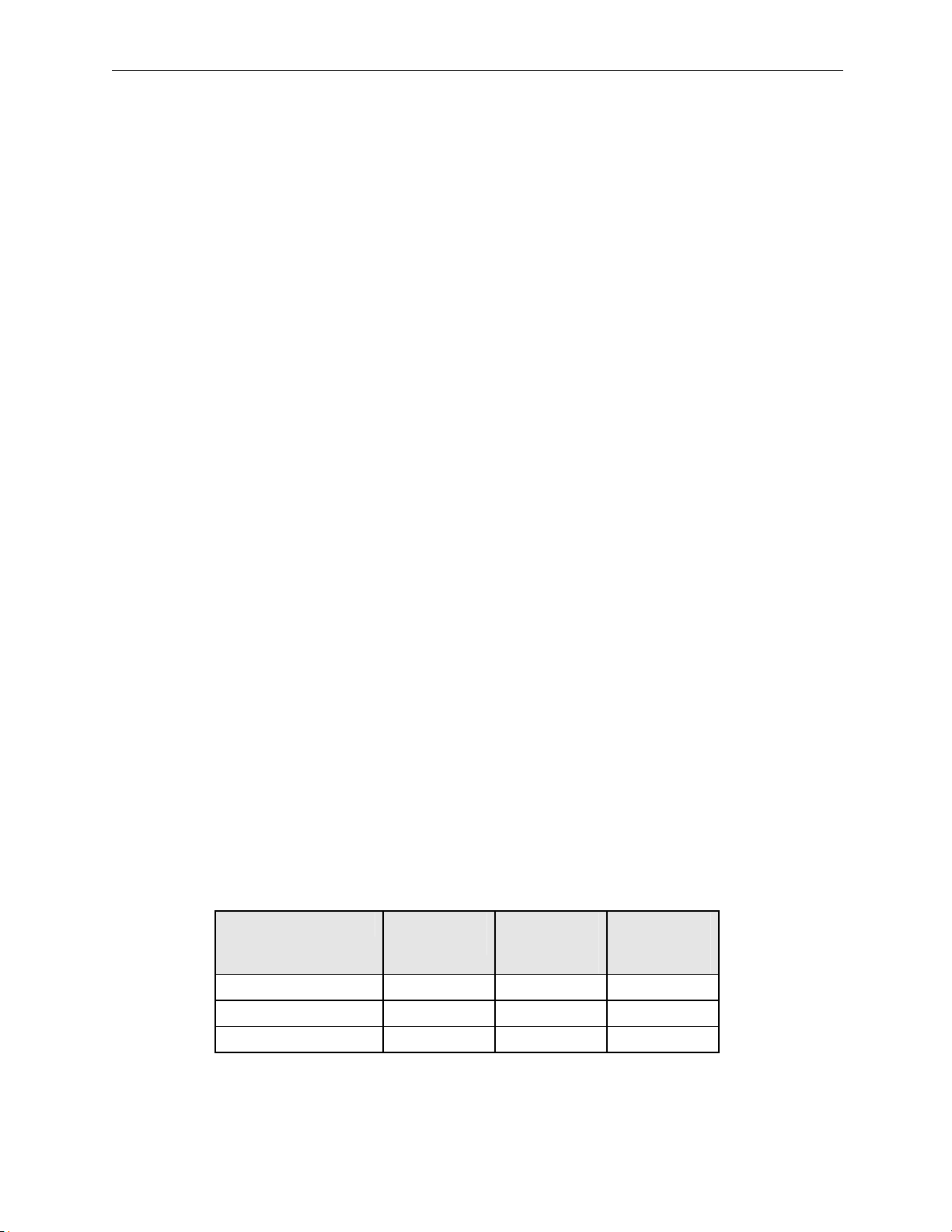
Transmission to the PC is at 9600 Baud, with 8 data bits, 1 stop bit, and no parity. Pin
assignments are as follows:
Function Tester
25-Pin ‘D’
Data In 2 3 2
Data Out 3 2 3
Signal Ground 7 5 7
PC
9-Pin ‘D’
(Com 1)
PC
25-Pin ‘D’
(Com 1)
(PC Interface Cable P/N 5211042)
NOTE
Pin numbers 2 and 3 are crossed when a 9-pin connector is on the PC.
Page 42
Page 34 Model 128/PC Instruction Manual
CHANGING POWER SETTING
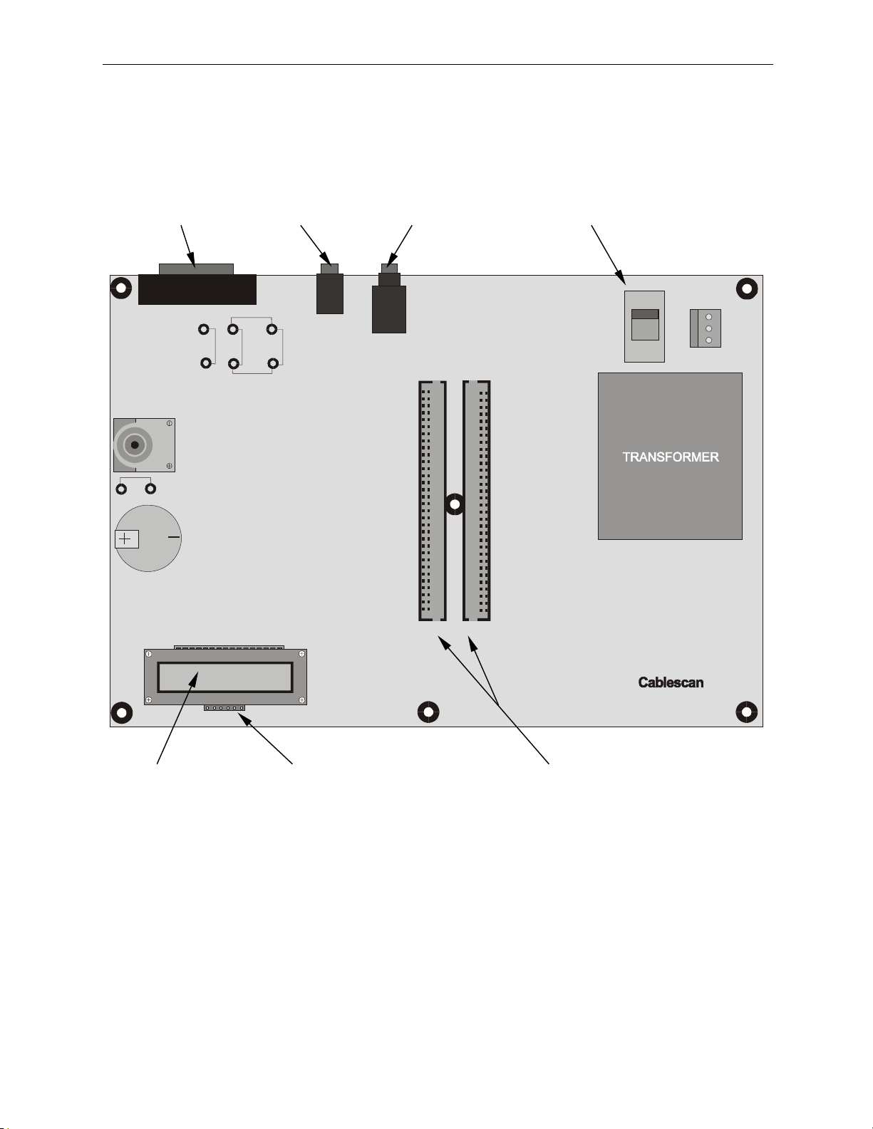
The Model 128/PC can be set to the other alternate power by opening the unit and changing an
internal Voltage Select switch (SW1) on the CPU Circuit Board (Figure 13) as follows:
1. Disconnect power cord from unit.
WARNING
Be sure the power is completely disconnected from the Model 128
before opening the unit and exposing the internal electronics.
Damage to the circuitry and/or injury to personnel could result.
2. Remove six Phillips-head screws holding the rear panel to the chassis and base plate.
Four (4) on the chassis and two (2) on the base plate.
3. Carefully pull the rear panel out only far enough to gain access to back of the CPU circuit
board directly behind the rear panel. (The rear panel is connected to the circuit board
with a short cable assembly.)
4. The Voltage Select switch is a red and black slide switch (labeled SW1) located on the
left-hand side of the CPU board. It has two power settings, and currently is set for the
power source indicated on the outside of the unit. Move the red slide switch to the
desired setting. For 115-volt operation, slide the switch toward the rear of the tester, and
for 220-volt operation, slide the switch towards the front of the tester.
5. Carefully replace the rear panel; install screws properly.
6. Label the power cord connector with the new power setting.
Page 43
Model 128/PC Instruction Manual Page 35
CPU CIRCUIT BOARD
Printer/Serial Enable Probe Voltage Select Switch
Connector Connector Connector (115 or 220)
SW1
J3
J1
W4
W2W3
W1
W5
J6
P1
115V
BUZZER
W6
LITHIUM
BATTERY
3vdc
REMOTE OUTPUT
JUMPERS
1
Mode l 12 8/ P C Ready
J7
16
J2
16
112
P5P4
2
ASSY NO. 5211057 REV __
MADE IN US A
Display Key Pad Connector Interface Fixture Connectors
Figure 13. Power Switch and Jumper Locations
Page 44
Page 36 Model 128/PC Instruction Manual
REMOTE OUTPUT SIGNALS
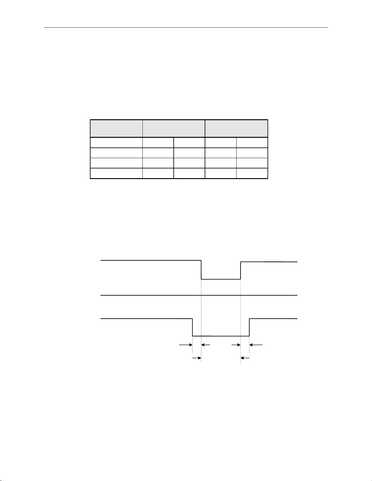
Two output signals are provided for controlling external devices through unused pins on the
printer/serial connector. The pins are connected to the CPU board where jumpers may be
installed to activate the signals. Refer to Figure 13 for jumper locations. The output signals are:
Pass/Fail and End of Test, and are brought out on pins 24 and 25, respectively. A jumper also is
provided for supplying +5vdc at pin 23. The pin assignments and labels used on the CPU board
are as shown below:
Function Standard Jumper
Setting
Alternate Jumper
Setting
Pass/Fail W2 Pin 24
End-of-Test W1 Pin 25
Ground - Pin 7
+5vdc W3 Pin 23
NOTE
The Standard Jumper settings, using W1 and W2, match the jumper
locations for the Model 256 and Model 256/PC testers. The Alternate
Jumper Setting, using W4 and W5 in lieu of W1 and W2, outputs the
signals on the same connector pins as the Model 512 jumper settings.
Refer to Figure 13 for jumper locations on the CPU board.
END-OF-TEST
PASS/FAIL
(Passed)
PASS/FAIL
(Failed)
2 ms 2 ms
W4 Pin 25
W5 Pin 24
- Pin 7
W3 Pin 23
15 ms
NOTE
Timing is approximate and can vary between testers.
Page 45
Model 128/PC Instruction Manual Page 37
ADAPTER CARDS
SELECTION
Cable adapters normally are employed in pairs, one for the left side of the interface fixture, and
one for the right side. Select each adapter to match its respective end of the cable being tested.
Cablescan adapters are described at the end of this manual. A list of adapter cards is provided
later in the section.
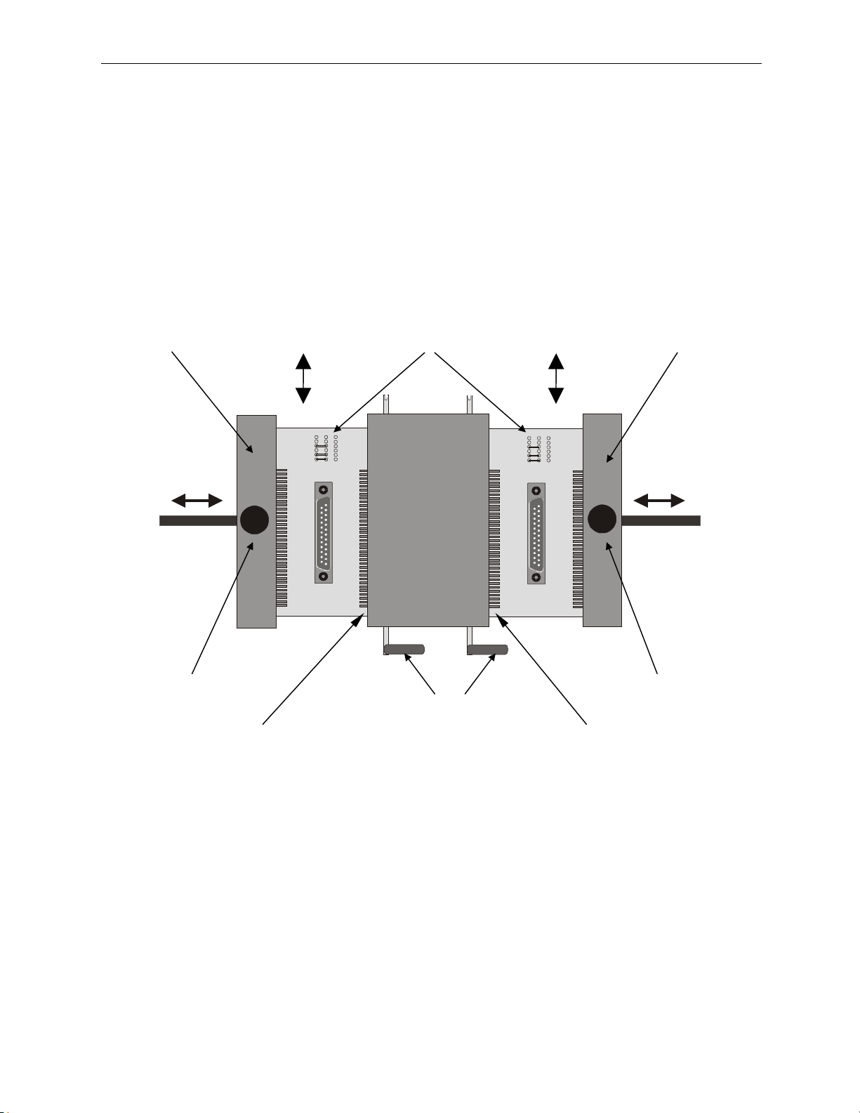
A SIDE B SIDE
Adjustable Remove/ Adapters Remove/ Adjustable
Hold-down Bar Insert Cards Insert Hold-down Bar
23456
1
111 2
8910
7
23456
1
111 2
8910
7
Knurled Knurled
Set Screw ZIF Levers Set Screw
A-01/Pin #1 (Top) ZIF Levers B-01/Pin #65 (Top
INSTALLATION
To install the adapters proceed as follows:
1. Open ZIF connector levers, slide adapter cards in from the top and all the way laterally
into their respective connectors. Each adapter card is designed to fit on either the right or
left side.
2. Loosen knurled set screw to slide adjustable hold-down bar in or out to accommodate
width of adapter card.
3. With adapter cards properly in place, close ZIF connector levers.
4. Run Self Test before a cable is installed to make sure no shorts are present due to damage
or improperly installed adapters.
CUSTOM ADAPTER CARDS
Page 46
Page 38 Model 128/PC Instruction Manual
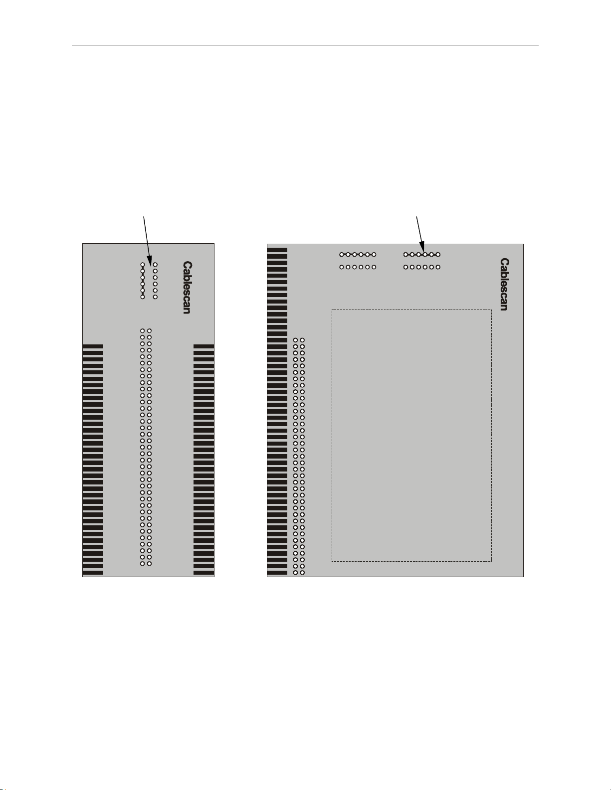
A Universal Adapter Card is available for mounting connectors that do not have a standard
adapter card available. The Universal Adapter Card is basically an extra wide circuit board with
plated-through holes connecting to the edge-card contacts. Unlike the standard adapter cards
which can be installed on either the left side or the right side of the fixture, the universal card is
wired to operate on one side or the other. This eliminates the need to double wire each contact
on the connector. Therefore, you should consider which side the adapter will work the best
before the card is wired. The standard and universal cards are shown below:
Adapter Card Adapter Card
Code Pins Code Pins
ASSY NO 5210900
RIGHT
123456
123456
Connector
Mounting Area
Standard Adapter Card Universal Adapter Card
Page 47
Model 128/PC Instruction Manual Page 39
SETTING ADAPTER CODES
All one-to-one cable wiring configurations, with the same number of conductors, will generate
the same signature code. The actual displayed signature, however, adds the code of each adapter
card into the signature code for the wire list. This generates unique coding for cables having the
same number of conductors but with different connector types.
At the top of each adapter card is a set of jumper locations. Jumpers on the adapter cards
supplied by Cablescan are preset. The code for each adapter is provided in the Adapter Card List
at the end of this section. The jumpers are not set when bare boards only (no connector
installed) are purchased from Cablescan. It is recommended that these jumpers be installed
when the connectors are being soldered to the bare boards, or when the Universal Cards are used
for custom adapters.
Converting Codes to Jumper Positions
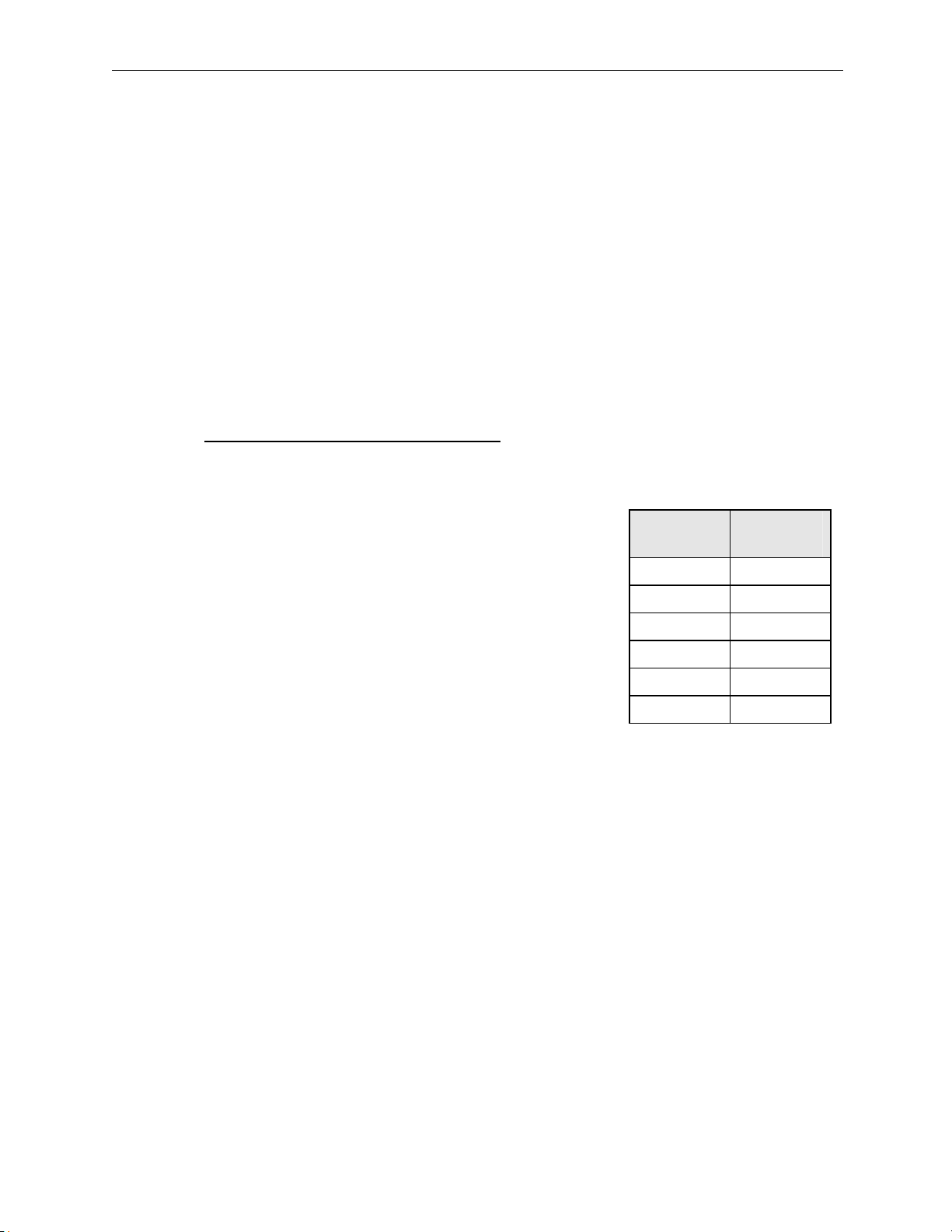
There are six sets of jumper locations at the top of the card.
The adapter card code is 0 when no jumpers are installed.
Jumpers are installed using a binary numbering method. A
jumper represents 1 when installed in a position. Use the
nearby table to determine the jumpers for a particular code.
Select the largest number in the binary number column that can
be subtracted from the code that will not produce a negative
number. For example, 4 would be the largest number that could
be subtracted from a code of 05. Take the results and select the
next largest number that could be subtracted from it. Therefore,
for a code of 05 the results would be 1 and the largest number is
1. Place jumpers across the locations of each number selected
from the table. Therefore, binary numbers 4 and 1 would
require jumpers at locations 3 and 1. (Binary numbers 16, 4,
and 1 would be selected for a code of 21 and require jumpers at
locations 5, 3, and 1.)
Location
Jumper
1 1
2 2
3 4
4 8
5 16
6 32
Binary
Number
Page 48

Page 40 Model 128/PC Instruction Manual
ADAPTER CARD LIST
Cablescan stocks a wide range of adapters for use with the Model 128. Adapters currently
available are listed below. Information on additional configurations may be obtained from
Cablescan.
PART TYPE PC BOARD ADAPTER
NUMBER TESTED DESCRIPTION NUMBER CODE
DIP CONNECTORS
5210894-50 Male 14-pin Dip 5004530 03
5210894-51 Male 16-pin Dip 5004530 03
5210894-54 Male 24-pin Dip 5004530 03
5210894-57 Male 40-pin Dip 5004530 03
5210894-59 Female 14&16 Dip Socket 5004530 04
.1" DUAL ROW PIN HEADERS
5210895-50 Female 10-pin Header 5004528 05
5210895-51 Female 16-pin Header 5004528 05
5210895-52 Female 20-pin Header 5004528 05
5210895-53 Female 26-pin Header 5004528 05
5210895-54 Female 34-pin Header 5004528 05
5210895-55 Female 40-pin Header 5004528 05
5210895-56 Female 50-pin Header 5004528 05
5210895-57 Female 60-pin Header 5004528 05
5210895-58 Female 64-pin Header 5004528 05
CARD EDGE CONNECTORS
5210896-50 Female 10-pin Card Edge 06
5210896-51 Female 16-pin Card Edge 06
5210896-52 Female 20-pin Card Edge 06
5210896-53 Female 26-pin Card Edge 06
5210896-54 Female 34-pin Card Edge 06
5210896-55 Female 40-pin Card Edge 06
5210896-56 Female 50-pin Card Edge 06
5210896-57 Female 60-pin Card Edge 06
(See Card Edge Connector replacement cards.)
PCB TRANSITION CONNECTORS
5210897-50 Male 10-pin PCB Transition 5004525 07
5210897-53 Male 20-pin PCB Transition 5004526 07
5210897-54 Male 26-pin PCB Transition 5004521 07
5210897-55 Male 34-pin PCB Transition 5004522 07
5210897-56 Male 40-pin PCB Transition 5004526 07
5210897-58 Male 50-pin PCB Transition 5004529 07
Page 49

Model 128/PC Instruction Manual Page 41
ADAPTER CARD LIST (CONTINUED)
PART TYPE PC BOARD ADAPTER
NUMBER TESTED DESCRIPTION NUMBER CODE
RIBBON CONNECTORS
5210901-50 Female 14-pin Champ 5004554 13
5210901-51 Male 14-pin Champ 5004555 14
5210901-52 Female 24-pin Champ 5004556 13
5210901-53 Male 24-pin Champ 5004557 14
5210901-54 Female 36-pin Champ 5004558 13
5210901-55 Male 36-pin Champ 5004559 14
5210901-56 Female 50 Pin Champ 5004560 13
5210901-57 Male 50 Pin Champ 5004561 14
5210901-58 Female 64-pin Champ 5004562 13
5210901-59 Male 64-pin Champ 5004563 14
"D"-SUB-MINIATURE
5210945-50 Female 9-pin "D" 5004549 12
5210945-51 Male 9-pin "D" 5004543 11
5210945-52 Female 15-pin "D" 5004550 12
5210945-53 Male 15-pin "D" 5004544 11
5210945-54 Female 25-pin "D" 5004551 12
5210945-55 Male 25-pin "D" 5004545 11
5210945-56 Female 37-pin "D" 5004552 12
5210945-57 Male 37-pin "D" 5004546 11
5210945-58 Female 50-pin "D" 5004553 12
5210945-59 Male 50-pin "D" 5004547 11
.050" D-Type (SCSI II Type)
5211016-50 Male 20-pin 5004579 18
5211016-51 Male 26-pin 5004580 18
5211016-52 Male 28-pin 5004581 18
5211016-53 Male 40-pin 5004582 18
5211016-54 Male 50-pin 5004583 18
5211016-55 Male 60-pin 5004584 18
Page 50

Page 42 Model 128/PC Instruction Manual
ADAPTER CARD LIST (CONTINUED)
PART TYPE PC BOARD ADAPTER
NUMBER TESTED DESCRIPTION NUMBER CODE
.050" DUAL ROW PIN HEADER
5210998-50 Female 10-pin Header 5004575 17
5210998-51 Female 20-pin Header 5004575 17
5210998-52 Female 30-pin Header 5004575 17
5210998-53 Female 40-pin Header 5004575 17
5210998-54 Female 50-pin Header 5004575 17
5210998-55 Female 60-pin Header 5004575 17
UNIVERSAL ADAPTER CARD
5210900 64-pin (maximum) 5004575 N/A
SINGLE ROW HEADER
5210918-50 Female 1 thru 24 pin .156 Header 5004540 16
EUROCARD CONNECTOR
5210919-50 Female 64-pin DIN Connector 5004568
MILLIMETER PATTERN BARE BOARD
1.5 mm x 1.5 mm, 2.0 mm x 2.0 mm, and 2.5 mm x 2.5 mm spacing.
3 Dual Rows of 64 pins
BARE PCB ONLY 5004603 CODE = 21
CARD EDGE CONNECTOR REPLACEMENT CARDS - (6 Cards per package)
5210589-30 Replacement 10-position Card Edge
5210589-31 Replacement 16-position Card Edge
5210589-32 Replacement 20-position Card Edge
5210589-33 Replacement 26-position Card Edge
5210589-34 Replacement 34-position Card Edge
5210589-35 Replacement 40-position Card Edge
5210589-36 Replacement 50-position Card Edge
5210589-37 Replacement 60-position Card Edge
ZIF CONNECTOR ASSEMBLY REPLACEMENTS
5210903-00 Left ZIF Connector Assembly
5210903-01 Right ZIF Connector Assembly
Page 51
Model 128/PC Instruction Manual Page 43
CARE OF THE MODEL 128/PC
MAINTENANCE
The most common source of trouble with the Model 128/PC is poor connection between the
adapter cards and the ZIF connectors. This problem can be prevented or reduced by routine
inspection for damage, wear, or foreign matter. Be especially aware that poor connections
during the Learn process will prevent a complete wire list program.
Cleaning of the controls, front panels, and other surfaces may be done with any mild soap and
water. All "wetted" areas must be thoroughly dried after cleaning. Be careful not to allow any
liquid to run into the Model 128/PC.
WARNING
Be sure the power is completely disconnected from the Model 128
before cleaning and thoroughly drying the unit. Damage to the
circuitry and/or injury to personnel could result.
REPAIR
If the Model 128/PC requires repair due to any defect of manufacture, and it is within the
warranty period, contact Cablescan, for instructions on returning it to the factory. Even if the
Model 128/PC is beyond the warranty period, and repair is necessary, it is advisable to return the
unit to the factory for repair.
If it is necessary for the user to replace parts, the replacement parts must be Cablescan, Inc.,
parts, or parts of equivalent rating and quality.
NOTE
Please read "Warranty" in the front of this manual.
MEMORY BACKUP BATTERY
If Error Code 05 is displayed, and it is determined that the memory battery is the cause, it is
recommended the battery be replaced by technicians at Cablescan.
REPLACEMENT PARTS
The following part numbers are provided for use in ordering replacements from Cablescan:
Enable Plug........................................................................................5210915
Wrist Strap Kit...................................................................................5210061
Printer (80-column serial).................................................................5210787
Printer Interface Cable.......................................................................5210791
PC Interface Cable.............................................................................5211042
PC Software (TERM) ........................................................................5210857
Battery................................................................................................6900014
ZIF Connector (Left) .........................................................................5210903
ZIF Connector (Left) .........................................................................5210903-01
Page 52

Model 128/PC Instruction Manual Page 44
Figure 14. Schematic - Model 128 CPU/Scanner Board (1 of 5)
Page 53

Figure 14. Schematic - Model 128 CPU/Scanner Board (2 of 5)
Model 128/PC Instruction Manual Page 45
Page 54

Model 128/PC Instruction Manual Page 46
Figure 14. Schematic - Model 128 CPU/Scanner Board (3 of 5)
Page 55

Figure 14. Schematic - Model 128 CPU/Scanner Board (4 of 5)
Model 128/PC Instruction Manual Page 47
Page 56

Model 128/PC Instruction Manual Page 48
Figure 14. Schematic - Model 128 CPU/Scanner Board (5 of 5)
Page 57

NOTES
Page 58

NOTES
Page 59

Cablescan
5900389 Rev D
 Loading...