

Page 1
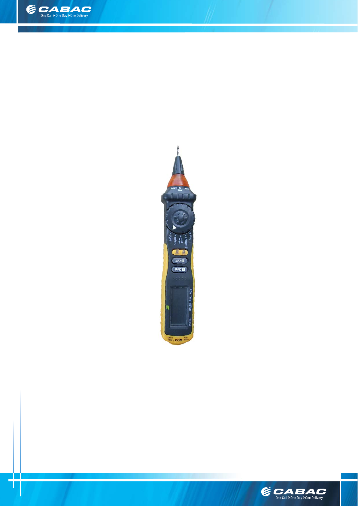
PEN TYPE DIGITAL MULTIMETER
OPERATION MANUAL
T8211D
T8211D
Customer Care Australia P: 133 122 F: 1300 303 310 E: [email protected] W: cabac.com.au
A: 8 Distribution Pl, Seven Hills NSW 2147
Customer Care New Zealand P: 8 0077 6969 F: 8 0088 6969 E: [email protected] W: cabac.co.nz
1
Page 2
To ensure safe operation, and in order to exploit to the full the functionality of the meter, please
follow the directions in this section carefully.
1. SAFETY INFORMATION
BE EXTREMELY CAREFUL IN THE USE OF THIS METER. Improper use of this device can result in
electric shock or destroy of the meter. Follow all safeguards suggested in this manual and the
normal safety precautions used in working with electrical circuits.
Do not service this device if you are not qualified to do so.
This meter has been designed according to IEC-1010 concerning electronic measuring instruments with an overvoltage
category CAT � 600V and pollution 2.
Follow all safety and operating instructions to ensure that the meter is used safely and is kept in good operating condition.
With proper use and care, the digital meter will give you years of satisfactory service.
Measurement category � is for measurements performed in the building installation. (Examples are measurements on
distribution boards, circuit-breakers, wiring, including cables, bus-bars, junction boxes, switches, socket-outlets in the fixed
installation, and equipment for industrial use and some other equipment, for example, stationary motors with permanent
connection to the fixed installation.)
1.1 PRELIMINARY
1.1.1 When using the meter, the user must observe all normal safety rules concerning:
- Protection against the dangers of electrical current.
- Protection of the meter against misuse.
1.1.2 When the meter is delivered, check that it has not been damaged in transit.
1.1.3 When poor condition under harsh preservation or shipping conditions caused, inspect and confirm this meter
without delay.
1.1.4 Test lead or test clip must be in good condition. Before using verify that the insulation on test lead or test clip is not
damaged and/or the leads wire is not exposed.
1.1.5 Full compliance with safety standards can be guaranteed only if used with test leads supplied.
If necessary, they must be replaced with the same model or same electric ratings.
1.2 DURING USE
1.2.1 Before using, you must select the right function and range.
1.2.2 Never exceed the protection limit values indicated in specifications for each range of measurement.
1.2.3 When the meter is linked to a measurement circuit, do not touch the probe tip of the meter and test lead (or test clip).
1.2.4 At the manual range, when the value scale to be measured is unknown beforehand, select the highest range.
1.2.5 Do not measure voltage if the voltage on the terminals exceeds 600V above earth ground.
1.2.6 Always be careful when working voltages above 60V DC or 30V AC rms, keep fingers behind the probe barrier while
measuring.
1.2.7 Never connect the meter leads across a voltage source while the transform switch is in the resistance, diode or
continuity mode. Doing so can damage the meter.
1.2.8 Never perform resistance, diode and continuity measurements on live circuits.
1.2.9 Before rotating the transform switch to change the function, disconnect the tip of meter and the probe
of the test lead (or test clip) from the circuit under test.
1.2.10 Never use the meter under the condition of the explosive air, steam or dirt.
1.2.11 If any faults or abnormalities are observed, the meter can not be used any more and it has to be checked out.
1.2.12 Never use the meter unless the rear case is in place and fastened fully.
1.2.13 Please do not store or use meter in areas exposed to direct sunlight, high temperature, humidity or condensation.
WARNING
Customer Care Australia P: 133 122 F: 1300 303 310 E: [email protected] W: cabac.com.au
A: 8 Distribution Pl, Seven Hills NSW 2147
Customer Care New Zealand P: 8 0077 6969 F: 8 0088 6969 E: [email protected] W: cabac.co.nz
2
Page 3
1.3 SYMBOLS
Important safety information, refer to the operating manual.
Double insulation(Protection classΙΙ)
Overvoltage (Installation) category III, Pollution Degree 2 per IEC1010-1 refers to the level of
Conforms to European union directive
Earth ground
AC
Alternating current
DC
AC or DC (alternating current or direct current)
Diode Continuity buzzer
M.H
The maximum value is being held.
D-H
This indicates that the display data is being held.
AUTO
Auto range
CAT
Impulse Withstand Voltage protection provided.
ΙΙ
Ι
Direct current
The battery is not sufficient for proper operation.
1.4 MAINTENANCE
1.4.1 Please do not attempt to adjust or repair the meter by removing the rear case while voltage is being applied.
A technician who fully understands danger involved should only carry out such actions.
1.4.2 Before opening the battery cover or case of the meter, always disconnect the tip of meter and the probe of the test lead
(or test clip) from all tested circuits.
1.4.3 To avoid the wrong reading causing electricity attack, when the meter displays“
”, you must change the battery.
1.4.4 Do not use abrasives or solvents on the meter, use a damp cloth and mild detergent only.
1.4.5 Always set the transform switch to the OFF position when the meter is not in use.
1.4.6 If the meter is to be stored for a long period of time, the batteries should be removed to prevent damage to the unit.
2. DESCRIPTION
- This meter is a portable professional measuring instrument with handsome LCD easily reading.
- Single operation of a transform switch makes measurement convenient. Overload protection and low battery indication
are provided, this meter is ideal for use in the fields, workshop, school, hobby and home applications.
- This meter has function of auto range and manual range.
- This meter has function of auto power off.
- This meter is with the functions of data hold and maximum value measure and hold.
- When using, it can show ranges engineering unit enunciators measuring results.
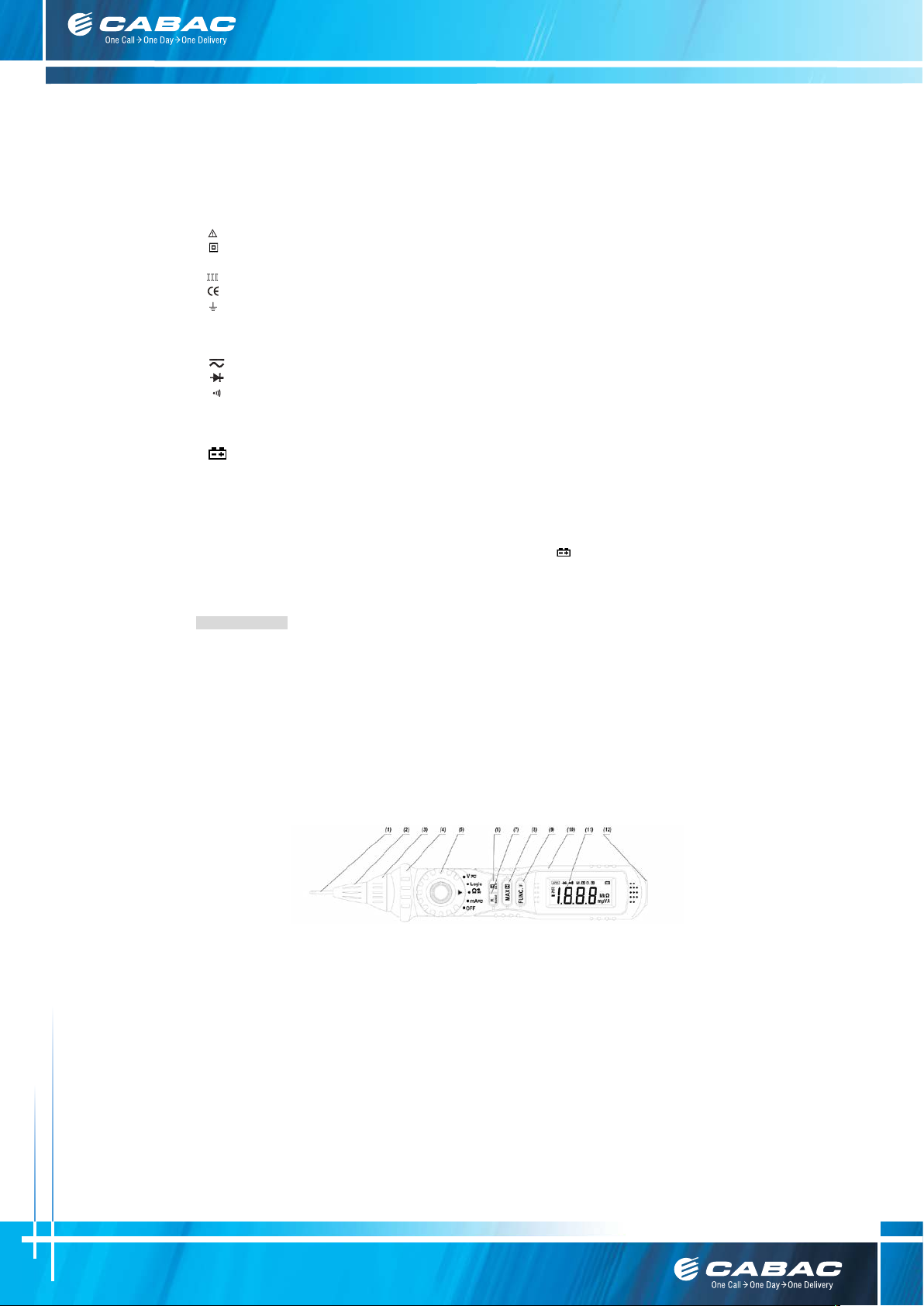
2.1 NAMES OF COMPONENTS
1 Probe
2 Rotatable Probe Socket
3 LED Indicator
4 Protection Ring
5 Transform Switch
6 DATA -H Button
7 RANGE Button
8 MAX.H Button
9 FUNC. Button
10 Panel
11 LCD Display
12 COM Jack
Customer Care Australia P: 133 122 F: 1300 303 310 E: [email protected] W: cabac.com.au
A: 8 Distribution Pl, Seven Hills NSW 2147
Customer Care New Zealand P: 8 0077 6969 F: 8 0088 6969 E: [email protected] W: cabac.co.nz
3
Page 4
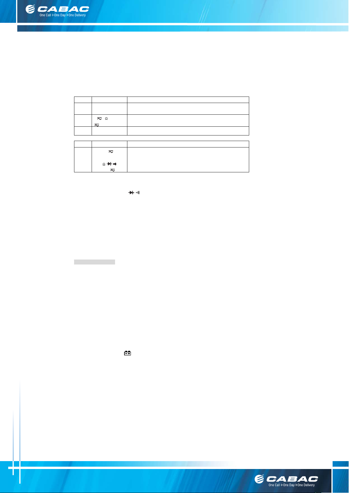
2.2 COMPONENTS ELUCIDATION
Button
Function
Operation performed
Power-up Option
This Button is used to hold data.
Disables automatic power-off feature.
Button
Function
Operation performed
mA
Switches between Resistance measurement, Diode Test and Continuity check.
- indicated for information about the Button operation.
DATA -H Any switch position
, Ω and mA
RANGE
V
MAX.H Any switch position Used to measure and hold the maximum value.
Used to transform Auto range or manual range.
FUNC.
- Transform Switch
This switch is used to select functions and desired ranges.
- Probe
Input terminals for V、mA、Ω/
- COM Jack
Common terminal for measurement.
- LCD Display
The measuring result will be displayed.
- LED Indicator
At Logic test range, High level and Low level can be indicated.
- Rotatable Probe Socket
Rotating the probe in or out of the meter.
- Protection Ring
To keep the hand from the probe behind the ring.
V
Logic
Ω
Switches between dc and ac voltage.
Keep pressing during the Logic testing.
Switches between dc and ac current.
/ and logic test.
3. SPECIFICATIONS
Accuracy is specified for a period of year after calibration and at 18℃ to 28℃(64℉ to 82℉)with relative humidity to 75%.
3.1 GENERAL SPECIFICATIONS
3.1.1 Environment conditions:
600V CAT. III
Pollution degree: 2
Altitude < 2000m
Operating temperature: 0~40℃, 32℉~122℉(<80% RH, <10� non-condensing)
Storage temperature: -10~50
3.1.2 Max. Voltage Between Terminals And Earth Ground: 600V DC or AC
3.1.3 Auto ranges and manual range.
3.1.4 Display: 20mm LCD
3.1.5 Max. Show Value: 1999 (3 1/2)
3.1.6 Polarity Indication: ‘-’indicates negative polarity.
3.1.7 Overrange Indication: Display ‘OL’.
3.1.8 Sampling Time: approx. 0.4 second
3.1.9 Unit showing: showing of function and electrical capacity.
3.1.10 Low Battery Indication: ‘
3.1.11 Fuse Protection: mA: resettable fuse
3.1.12 Auto power off time: 15 min.
3.1.13 Power Supply: 1.5V×2 AAA battery.
3.1.14 Dimension: 208×38×29 mm
3.1.15 Weight: approx. 110g(including battery)
℃, 14℉~122℉(<70% RH, battery removed)
’ displayed
Customer Care Australia P: 133 122 F: 1300 303 310 E: [email protected] W: cabac.com.au
A: 8 Distribution Pl, Seven Hills NSW 2147
Customer Care New Zealand P: 8 0077 6969 F: 8 0088 6969 E: [email protected] W: cabac.co.nz
4
Page 5
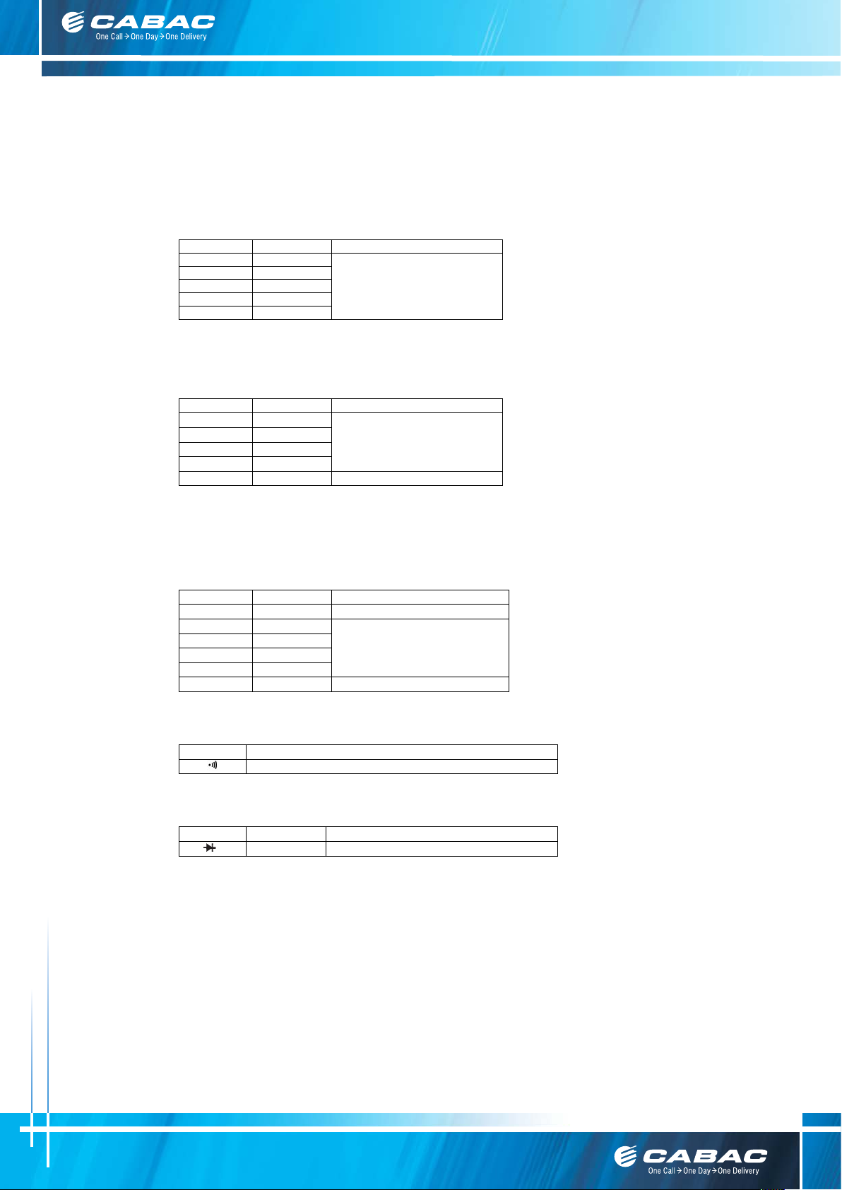
Range
Resolution
Accuracy
200mV
0.1mV
2V
0.001V
20V
0.01V
±(0.7% of rdg + 2 digits)
200V
0.1V
600V
1V
200mV
0.1mV
2V
0.001V
±(0.8% of rdg + 3 digits)
200V
0.1V
600V
1V
±(1.0% of rdg + 3 digits)
Range
Resolution
Accuracy
2kΩ
0.001kΩ
20kΩ
0.01kΩ
±(1.0% of rdg + 1 digit)
200kΩ
0.1kΩ
20MΩ
0.01MΩ
±(1.0% of rdg + 5 digits)
Range
Function
Built-in buzzer will sound, if resistance is lower than 50Ω.
Range
Resolution
Function
0.001V
Display: read approximate forward voltage of diode
3.2 ELECTRICAL SPECIFICATIONS
Circumstance Temperature: 23±5℃ Relative Humidity: < 75%
3.2.1 DC Voltage
- Input Impedance: 10MΩ
- Overload Protection: 200mV range: 250V DC or AC rms,
- Max. Input Voltage: 600V DC
3.2.2 AC Voltage
Range Resolution Accuracy
20V 0.01V
- Input Impedance: 10MΩ
- Overload Protection: 200mV range: 250V DC or AC rms,
- Frequency Range: 40 to 400Hz
- Response: Average, calibrated in rms of sine wave.
- Max. Input Voltage: 600V rms AC
3.2.3 Resistance
2V-600V ranges: DC 600V or AC 600V rms.
2V-600V ranges: DC 600V or AC 600V rms.
200Ω 0.1Ω ±(1.0% of rdg + 3 digits)
2MΩ 0.001MΩ
- Open Circuit Voltage: 0.25V
- Overload Protection: 250V DC or rms AC
3.2.4 Continuity
- Open circuit voltage: approx. 0.5V
- Overload Protection: 250V DC or rms AC
3.2.5 Diode
- Forward DC Current: approx. 1mA
- Reversed DC Voltage: approx.1.5V
- Overload Protection: 250V DC or rms AC
Customer Care Australia P: 133 122 F: 1300 303 310 E: [email protected] W: cabac.com.au
A: 8 Distribution Pl, Seven Hills NSW 2147
Customer Care New Zealand P: 8 0077 6969 F: 8 0088 6969 E: [email protected] W: cabac.co.nz
5
Page 6
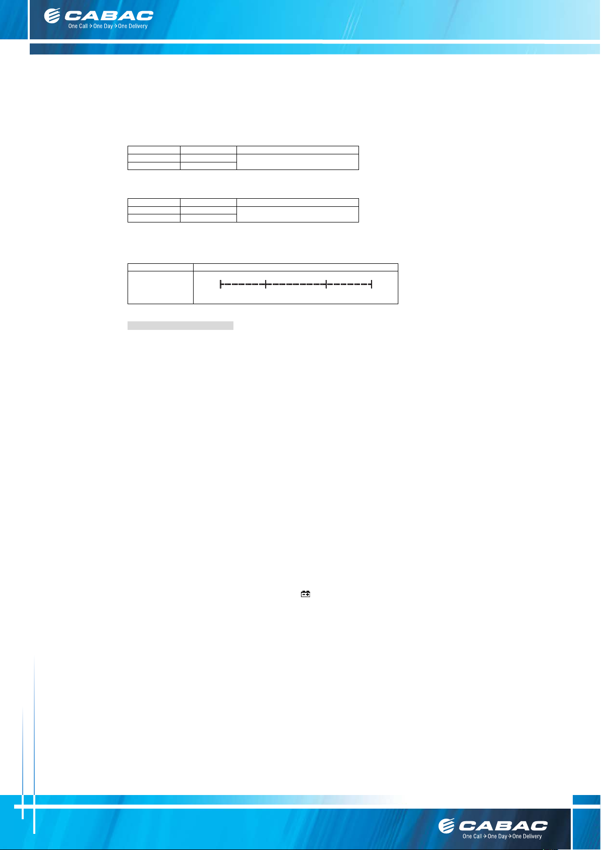
3.2.6 DC Current
Range
Resolution
Accuracy
20mA
0.01mA
200mA
0. 1 mA
±(1.5% of rdg + 3 digits)
Range
Resolution
Accuracy
20mA
0.01mA
200mA
0. 1 mA
±(2.0% of rdg + 3 digits)
Range
Description
0V 1.5V 3.5V
5V
Low "0" High "1"
Green
LED on
Green, Red
LED off
Red LED
on
- Overload Protection: Resettable fuse.
3.2.7 AC Current
- Overload Protection: Resettable fuse.
- Frequency Range: 40Hz-200Hz
- Response: Average, calibrated in rms of sine wave
3.2.8 Logic Test
Logic
- Input Impedance: approx. 1MΩ - Overload Protection: 250V DC or rms AC
4. OPERATING INSTRUCTION
4.1 DATA HOLD
If you need data hold when measuring, you can put on “DATA -H” button, it will hold the reading; if you put the button again,
data hold is not continue.
4.2 MAXIMUM VALUE MEASURING AND HOLD
At the range of voltage, you can put on “MAX.H” button, it will hold the maximum value; if you put the button again, the
maximum value will not be held.
4.3 FUNCTION TRANSFORM
Put down the "FUNC." button when measuring the voltage. Meter will be transformed between DC and AC range.
Put "FUNC." button when measuring the resistance, diode and continuity, meter will transform among them.
4.4 RANGE TRANSFORM
The auto range is used when measuring the voltage and resistance. Put down the "RANGE" button if the manual range is
needed. Each time you put down, range will go upward; the minimum range is transformed if "RANGE" button is put down at
the maximum range. If the "RANGE" button is put down more than two seconds, auto range is used again.
4.5 AUTO POWER OFF
If there’s no any operation within fifteen minutes after power is on, meter will auto power off with five short sounds and a long
sound in a minute.
After auto power off, if stir the transform switch or put down any button of “FUNC.”, ”MAX.H”, ”RANGE”, meter will recover
the working condition.
If presses the “DATA -H” button when power is on, auto power off disable. In sleep mode, the auto power off function will be
cancelled if presses the “DATA -H” button to wake the meter.
4.6 PREPARATION FOR MEASUREMENT
4.6.1 Set the transform switch to the right range. At the manual range, when the value scale to be measured is unknown
beforehand, select the highest range.
4.6.2 When measuring, at first, connect to the public (COM) testing line, then connect the probe tip of the meter to the circuit
under test.
4.6.3 If the battery voltage is less than 2.4V, display will show “
”, the battery should be changed at this time.
Customer Care Australia P: 133 122 F: 1300 303 310 E: [email protected] W: cabac.com.au
A: 8 Distribution Pl, Seven Hills NSW 2147
Customer Care New Zealand P: 8 0077 6969 F: 8 0088 6969 E: [email protected] W: cabac.co.nz
6
Page 7
4.7 MEASURING DC VOLTAGE
Pay attention to avoid getting an electric shock when measuring high voltage.
Pay attention to avoid getting an electric shock when measuring voltage.
Risk of Electrocution.
You can’t input the voltage which is higher than 600V DC, it’s possible to show higher voltage, but
it may damage the inner circuit or cause electrical shock.
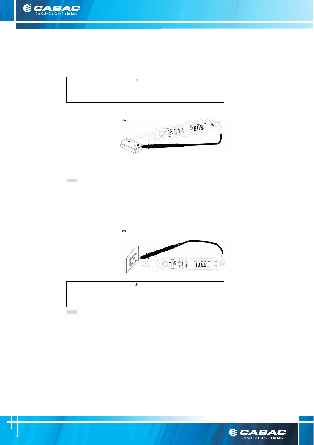
4.7.1 Rotate the probe socket clockwise to spin out the probe from the meter.
4.7.2 Insert the black test lead or test clip in the COM jack.
4.7.3 Set the transform switch at the V
range position.
4.7.4 Press the "FUNC." Button
to transform to DC measurement.
Auto range and manual range
can be transformed by
pressing the “RANGE”
button.
4.7.5 Connect the probe tip of the meter and probe tip of the test lead (or test clip) across the power source or be loaded
on the two sides under measurement.
4.7.6 You can get a reading from LCD display. The polarity of the tested terminal which the tip of the meter connection will
be indicated.
NOTE:
- At the little voltage range, the meter will show unsteady reading when test leads haven’t reach the circuit, it’s normal
because the meter is very sensitive. When the meter touches the circuit, you can get the true reading.
- At the manual range mode, when only the figure ‘OL’ is displayed, it indicates over-range situation and the higher range
has to be selected.
- At the manual range mode, when the value scale to be measured is unknown beforehand, select the range to the highest
position and set down gradually.
4.8 MEASURING AC VOLTAGE
4.8.1 Rotate the probe socket clockwise to spin out the probe from the meter.
4.8.2 Insert the black test lead or test clip in the COM jack.
4.8.3 Set the transform switch at the V
4.8.4 Press the "FUNC." button to transform to AC measurement.
Auto range and manual range can be transformed
by putting the “RANGE” button.
4.8.5 Connect the probe tip of the meter
to one side of the tested circuit
and probe tip of the test lead
(or test clip) to the other side.
4.8.6 You can get reading from
LCD display.
Risk of Electrocution.
You can’t input the voltage which is higher than 600V rms AC, it’s possible to show higher voltage,
but it may damage the inner circuit or cause electrical shock.
WARNING
range position.
WARNING
NOTE:
- At the manual range mode, when only the figure ‘OL’ is displayed, it indicates over-range situation and the higher range
has to be selected.
- At the little voltage range, the meter will show unsteady reading when test leads haven’t reach the circuit, it’s normal
because the meter is very sensitivity. When test leads touch the circuit, you can get the true reading.
- At the manual range mode, when the value scale to be measured is unknown beforehand, select the range at the highest
position and set down gradually.
- Transform to the manual range when use the mV range.
Customer Care Australia P: 133 122 F: 1300 303 310 E: [email protected] W: cabac.com.au
A: 8 Distribution Pl, Seven Hills NSW 2147
Customer Care New Zealand P: 8 0077 6969 F: 8 0088 6969 E: [email protected] W: cabac.co.nz
7
Page 8
4.9 MEASURING RESISTANCE
that all capacitors have been discharged fully.
all capacitors have been discharged fully.
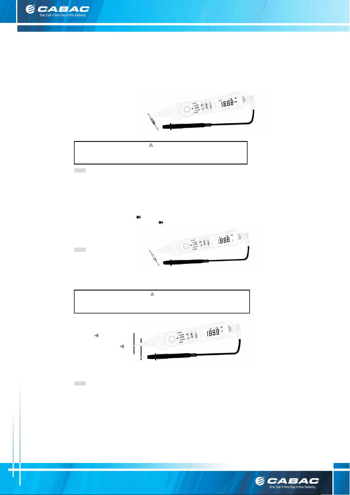
4.9.1 Rotate the probe socket clockwise to spin out the probe from the meter.
4.9.2 Insert the black test lead or test clip in the COM jack
4.9.3 Set the transform switch at the Ω range position.
Auto range or manual range can be transformed
by putting the “RANGE” button.
4.9.4 Connect the probe tip of the
meter to one side of the tested
circuit and probe tip of the test
lead (or test clip) to the other side.
4.9.5 You can get reading from LCD display.
Risk of Electrocution.
When measuring in-circuit resistance, be sure the circuit under test has all power removed and
NOTE:
- At the manual range mode, when only the figure ‘OL’ is displayed, it indicates over-range situation and the higher range
has to be selected.
- For measuring resistance above 1MΩ, the meter may take a few seconds to get stable reading.
- When the input is not connected, i.e. at open circuit, the figure ‘OL’ will be displayed for the over-range condition.
4.10 TESTING DIODE
4.10.1 Rotate the probe socket clockwise to spin out the probe from the meter.
4.10.2 Insert the black test lead or test clip in the COM jack.
4.10.3 Set the transform switch at the
4.10.4 Put down the "FUNC." button transformed at
4.10.5 Connect the probe tip of the meter to the anode of the diode,
the black test lead (or test clip) to the cathode of the diode.
4.10.6 You can get reading from LCD display.
NOTE:
- The meter will show the
approximate forward voltage
drop of the diode.
- If the meter and the lead connection is reversed, only figure ‘OL’ will be displayed.
- When the input is not connected, i.e. at open circuit, the figure ‘OL’ will be displayed.
4. 11 CONTINUITY TEST
Risk of Electrocution.
When testing the circuit continuity, be sure that the power of the circuit has been shut down and
range position.
.
WARNING
test.
WARNING
4.11.1 Rotate the probe socket clockwise to spin out the probe from the meter.
4.11.2 Insert the black test lead or test clip in the COM jack.
4.11.3 Set the transform switch
4.11.4 Put down the "FUNC."
4.11.5 Connect the probe tip of
tested circuit and probe tip of the test lead (or test clip) to the other side.
4.11.6 If continuity exists (i.e., resistance less than about 50Ω), built-in buzzer will sound.
NOTE:
- If the input open circuit (or the circuit resistance measured is higher than 200Ω), then the figure‘0L’ will be displayed.
Customer Care Australia P: 133 122 F: 1300 303 310 E: [email protected] W: cabac.com.au
A: 8 Distribution Pl, Seven Hills NSW 2147
Customer Care New Zealand P: 8 0077 6969 F: 8 0088 6969 E: [email protected] W: cabac.co.nz
range position.
at the
button transformed at
continuity test.
the meter to one side of the
8
Page 9
4.12 MEASURING DC CURRENT
measurement where the open-circuit potential to earth is greater than 250V.
measurement where the open-circuit potential to earth is greater than 250V.
cause electrical shock. Pay attention to avoid getting an electric shock when testing logic level.
Risk of Electrocution.
To avoid damage to the Meter or injury if the fuse blows, never attempt an in-circuit current
4.12.1 Rotate the probe socket clockwise to spin out the probe from the meter.
4.12.2 Insert the black test lead or test clip in the COM jack.
4.12.3 Set the transform switch at the mA
4.12.4 Press the "FUNC." bu tton to transform to DC measurement. Auto range and manual range can be transformed by
pressing the “RANGE” button.
4.12.5 Connect the probe tip of the meter and probe tip of the test lead (or test clip) in series with the load in which the
current is to be measured.
4.12.6 You can get a reading from LCD display. The polarity of the tested terminal which the tip of the meter connection will
be indicated.
NOTE:
- At the manual range mode, when only the figure ‘OL’ is displayed, it indicates over-range situation and the higher range
has to be selected.
4.13 MEASURING AC CURRENT
Risk of Electrocution.
To avoid damage to the Meter or injury if the fuse blows, never attempt an in-circuit current
4.13.1 Rotate the probe socket clockwise to spin out the probe from the meter.
4.13.2 Insert the black test lead or test clip in the COM jack.
4.13.3 Set the transform switch at the mA
4.13.4 Press the "FUNC." button to transform to AC measurement. Auto range and manual range can be transformed by
putting the “RANGE” button.
4.13.5 Connect the probe tip of the meter and probe tip of the test lead (or test clip) in series with the load in which the
current is to be measured.
4.13.6 You can get reading from LCD display.
NOTE:
- At the manual range mode, when only the figure ‘OL’ is displayed, it indicates over-range situation and the higher range
has to be selected.
4.14 LOGIC TEST
Risk of Electrocution.
You can’t input the voltage which is higher than 100V rms AC, it may damage the inner circuit or
WARNING
range position.
WARNING
range position.
WARNING
4.14.1 Rotate the probe socket anti-clockwise to spin the probe into the meter.
4.14.2 Insert the black test clip in the COM jack.
4.14.3 Set the transform switch at the Logic range position.
4.14.4 Connect the black test clip to the GND(-) of the circuits being measured.
4.14.5 Keep pressing the “FUNC” button and Touch the tip to the testing object in the circuits being measured. And observe
the logic state indicated by LED light. (Red LED light expresses high level/logic “1” and green LED light expresses low
level/logic “0”)
4.14.6 Also you can get reading and sign “ “ or “ “ from LCD display (“ “ expresses high level/logic “1” and
“ “expresses low level/logic “0”).
NOTE:
- If the input open circuit (or the object’s logic state is lower than 1.5V), the green LED will be lighted.
- You must keep pressing the “FUNC” button during the logic testing.
Customer Care Australia P: 133 122 F: 1300 303 310 E: [email protected] W: cabac.com.au
A: 8 Distribution Pl, Seven Hills NSW 2147
Customer Care New Zealand P: 8 0077 6969 F: 8 0088 6969 E: [email protected] W: cabac.co.nz
9
Page 10
� Test Lead: Electric Ratings 600V 10A
one piece
� Test Clip: Electric Ratings 600V 10A
one piece
� Battery: 1.5V, AAA
two pieces
5. MAINTENANCE
5.1 BATTERY REPLACEMENT
Before attempting to open the battery cover of the meter, be sure that the probe tip of the meter
and test lead (or test clip) have been disconnected from measurement circuit to avoid electric
shock hazard.
5.1.1 If the sign ‘
5.1.2 Loosen the screw fixing the battery cover and remove it.
5.1.3 Replace the exhausted battery with a new one.
5.1.4 Put the battery cover as its origin.
5.2 TEST LEADS (OR TEST CLIP) REPLACEMENT
Full in compliance with safety standards can be guaranteed only if used with test leads supplied.
If necessary, they must be replaced with the same model or same electric ratings. Electric ratings
of the test leads: 600V 10A.
You must be replaced the test lead if the lead is exposed.
6. ACCESSORIES
� Instruction Manual one piece
Using this appliance in an environment with a strong radiated radio-frequency electromagnetic field (approx. 3V/m), may influence
its measuring accuracy. The measuring result can be strongly deviating from the actual value.
’ appears on the LCD display, it indicates that the battery should be replaced.
WARNING
WARNING
CAUTION
Customer Care Australia P: 133 122 F: 1300 303 310 E: [email protected] W: cabac.com.au
A: 8 Distribution Pl, Seven Hills NSW 2147
Customer Care New Zealand P: 8 0077 6969 F: 8 0088 6969 E: [email protected] W: cabac.co.nz
10
 Loading...