

Page 1
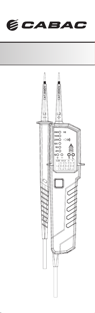
Voltage Tester
3031 Manual
G Manual
Page 2

Page 3

Content
Content
1. Introduction / Product Package ............................5
2. Safety Measures ...................................................5
3. Danger of electric shock and other dangers ........5
4. Intended Use ........................................................6
5. Tester Information ................................................7
6. Preparation for tests .............................................8
6.1 Auto-power-on/ switching on .....................8
6.2 Auto-power off ...........................................8
7. Conducting Tests .................................................8
7.1 Voltage test ..............................................8
7.2 Single-pole phase test ..............................8
7.3 Phase rotation test ...................................8
7.4 Continuity test ..........................................9
7.5 Torch light ..................................................9
8. Battery Replacement ............................................9
9.Technical data ........................................................9
10. Cleaning and storage ......................................10
ENGLSIH
3
Page 4

References
References marked on tester or in instruction manual:
Warning of a potential danger, comply with instructi-
on manual.
Reference. Please pay utmost attention.
Caution! Dangerous voltage. Danger of electrical
shock.
Continuous double or reinforced insulation complies
with category II DIN EN 61140.
Conformity symbol, the instrument complies with the
valid directives. It complies with the EMV Directive
(89/336/EEC), Standard EN 61326-1 are fullled. It
also complies with the Low Voltage Directive (73/23/
EEC), Standard EN61243-3:2010 is fullled.
Tester complies with the standard (2002/96/EG)
WEEE
The instruction manual contains information and
references, necessary for safe operation and maintenance of the tester.
Prior to using the tester (commissioning/ assembly)
the user is kindly requested to throughly read the instruction manual and comply with it in all sections.
Failure to read the tester manual or to comply with the
warnings and references contained herein can result in serious bodily injury or tester damage.
The respective accident prevention regulations es-
tablished by the professional associations are to be
strictly enforced at all times
1. Introduction / Product Package
The voltage tester 3031 is universally applicable testers
for voltage testing, continuity testing and rotary eld testing.
The testers are constructed according to the latest safety
regulations and guarantee safe and reliable working.
The voltage tester 3031 is characterized by the
following features:
• Designed to meet international safety standards.
EN61243-3:2010
• Measurement Category (CAT.) IV 600V
• AC and DC voltage test up to 690V with LEDs and
LCD
• Polarity indication
• Single-pole phase test
• Phase rotation test
• Continuity test
• Auto-power ON / OFF
• Torch light
• IP64 (IEC60529)
4
Page 5
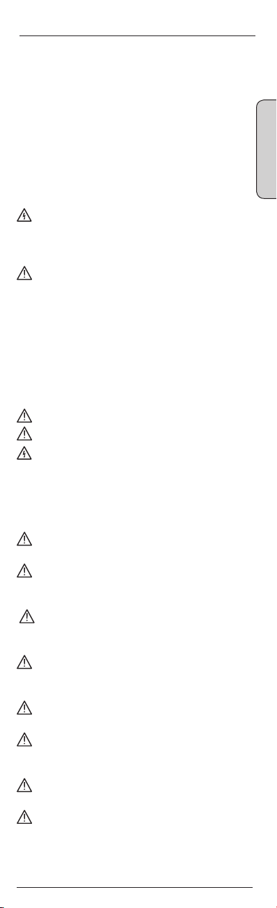
After unpacking, check that the instrument is undamaged. The product package comprises:
1 pc Tester 3031
2 pcs 4mm test tip adapters
2 pcs CAT III/ 1000V test tip cover
2 pcs batteries 1.5V, IEC LR03
1 pc operating instructions
2. Safety Measures
The testers have been constructed and tested in
accordance with the safety regulations for voltage
testers and have left the factory in a safe and perfect
condition.
The operating instructions contain information and
References required for safe operation and use of
the tester. Before using the tester, read the operating instructions carefully and follow them in all respects.
3. Danger of electric shock and other
dangers
Only to be used by a competent person.
Prove on a known live before and after testing.
To avoid an electric shock, observe the precautions
when working with voltages exceeding 120 V (60 V)
DC or 50 V (25 V) eff AC. In accordance with DIN
VDE these values represent the threshold contact
voltages (values in brackets refer to limited ranges,
e.g. in agricultural areas).
The tester must not be used with the battery
compartment open
Before using the tester, ensure that the test lead and
device are in perfect working order. Look out e.g. for
broken cables or leaking batteries.
Hold the tester and accessories by the designated grip
areas only, the display elements must not be covered.
Never touch the test probes.
The tester may be used only within the specied
measurement ranges and in low-voltage installations
up to 690 V.
The tester may be used only in the measuring circuit
category it has been designed for.
Before and after use, always check that the tester is in
perfect working order (e.g. on a known voltage source).
The tester must no longer be used if one or more
functions fail or if no functionality is indicated.
It is not permitted to use the tester during rain or
precipitation.
ENGLSIH
5
Page 6

Danger of electric shock & other dangers
A perfect display is guaranteed only within a tem-
perature range of -15°C to +55°C at an relative air
humidity less than 85%.
If the safety of the user cannot be guaranteed, the
tester must be switched off and secured against
unintentional use.
Safety is no longer guaranteed e.g. in the following
cases:
• obvious damage
• broken housing, cracks in housing
• if the tester can no longer perform the required
measurements/tests
• stored for too long in unfavorable conditions
• damaged during transport
• leaking batteries
The tester complies with all EMC regulations. Ne-
vertheless it can happen in rare cases that electric
devices are disturbed by the electrical eld of the
tester or the tester is disturbed by electrical devices.
Never use the tester in explosive environment
Tester must be operated by trained users only
Operational safety is no longer guaranteed if the tester
is modied or altered.
The tester may be opened by an authorized service
technician only.
4. Intended Use
The tester may be used only under the conditions and for the
purposes for which it was designed. Therefore, observe in
particular the safety instructions, the technical data including
environmental conditions.
6
Page 7
1 2 3
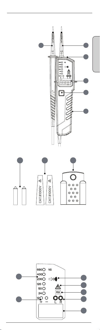
5. Tester Information
1) Test Probe L1
2) Test Tip L2
3) Torch Light
4) Display
5) Torch light button
6) Main Body
Accessory
1) 4 mm test Tips
2) Plug on cover (GS38)
3) Protective cover
1
2
3
ENGLSIH
4
5
6
Control elemets
1) Buzzer hole for acoustic indication
2) Singel Pole Test ELV Warning
3) Continuity Test
4) Rotary eld (left and right)
5) LCD Display indicating voltage, polarity and low battery
6) LEDs indicating 12V and polarity
7) Voltage Indication
7
1
2
3
6
4
5
7
Page 8

Preparation for tests
6. Preparation for tests
6.1 Auto-power-on/ switching on
• The tester switches on when it detects continuity, an AC
or DC voltage above apporx. 10V a live phase on L2
(single pole test).
• It can be switched on with the torch light button.
6.2 Auto-power off
• Tester is automatically powered off after 5 sec when
there is no signal contacted to the probes.
• The torch light switches off after approx. 10 sec.
7. Conducting Tests
7.1 Voltage test
• Connect both probes to the object under test.
• The voltage is indicated by LEDs and LCD (3031 only)
• Buzzer sounds when a threshold voltage of approx.
38VAC or approx. 100 VDC is exceeded.
• Voltage polarity is indicated in following manner.
→ AC: + and – 12V LED are on
→ +DC: +12V LED is on
→ -DC: -12V LED is on
When the L2 probe + is the positive (negative) po-
tential, the Polarity indication LED indicates “+DC”
(“-DC”).
During voltage test, L or R LED may light up.
In case of empty batteries, the ELV LED lights up
>50VAC, >120VDC
7.2 Single-pole phase test
Function of this test may not be fully achieved if the
insulation condition/ grounding conditions of user
or of the equipment under test aren’t good enough.
Verication of live-circuit shouldn’t be dependent on
this Single-pole phase test only, but on the voltage
test.
• Hold the tester good in your hand. Connect the “L2+”
probe to the object under test. Live circuit LED lights up
and buzzer sounds when a voltage of approx. 100V AC
or more exists in the object under test. (Pol≥100VAC).
7.3 Phase rotation test
• L LED and R LED for Phase rotation test may operate on
various wiring systems, but effective testing result can be
obtained only on three-phase 4-wire system.
• Hold the tester good in your hand and connect both pro-
bes to the object under test.
• Phase-to-phase voltage is indicated by Voltage LEDs.
• R LED lights up for Right rotary eld.
8
Page 9

Battery Replacement
• L LED lights up for Left rotary eld.
• Measurement principle: The instrument detects the phase rising order regarding the user as earth.
Function of this test may not be fully achieved if the
insulation condition/ grounding conditions of user or of
the equipment under test is not good enough.
7.4 Continuity test
Make sure the object under test isn’t live.
• Connect both test probes to the object under test. Con-
tinuity LED lights up and buzzer sounds continuously to
indicate continuity
7.5 Torch light
• Pressing the torch light button to turn on the light and
after approx. 10s it will turn itself off
8. Battery Replacement
Remove the probes from any testing point, when
opening the Battery case. Batteries are dead when
the continuity test with both test probes connected
cannot be done anymore. A battery symbol in the
LCD indicates low battery.
Follow the procedure below and replace batteries with
new ones (type IEC LR03 1.5V).
• Unscrew the battery door, e.g. with a coin.
• Pull out the Battery door and replace the batteries. Insert
new batteries according to the engraving on the Battery
door.
• Re-assemble battery door.
• Conrm that the Battery door case is properly locked
prior to measurements.
ENGLSIH
9
Page 10

Battery Replacement
9. Technical data
Voltage range: 12…690V AC (16…400Hz),
DC(±)
LED Nominal voltage: 12/24/50/120/230/400/690V, AC
(16…400Hz), DC(±)
LED tolerances according to
EN61243-3
ELV indication LED: >50VAC, >120VDC
Response time: < 1s at 100% of each
nominal voltage
LCD Range: 0…690V, AC (16…400Hz),
DC(±)
LCD Resolution: 0.1V
LCD Accuracy: ±3%±5dgt (0…690V)
LCD Overrange
indication: “OL”
Peak current: Is<3.5mA (at 690V)
Measurement Duty: 30s ON (operation time),
240s OFF (recovery time)
Internal battery
consumption: approx. 80mA
Single-pole phase test
voltage range: 100…690V AC (50/60Hz)
Phase rotation test: 120…400V earth-to-phase,
AC 50/60Hz
Continuity test: Detection range 0…500kΩ +
50%
Battery: 3V (IEC LR03 1.5V x 2)
Temperature: -15…55°C operation; -20…70°C
storage, No condensation
Humidity: Max 85% RH
Altitude: up to 2000m
Overvoltage: CAT III/1000V, CAT IV 600V
Standard: EN61243-3:2010
Pollution: degree 2
Protection: IP 64
10
Page 11

Cleaning and storage
10. Cleaning and storage
Tester does not need any special maintenance if used
according to user manual.
Remove tester from all test points before cleaning.
Use a lightly damp cloth with neutral detergent for
cleaning the instrument. Do not use abrasives or
solvents.
Do not expose the instrument to direct sun light, high
temperature and humidity or dewfall.
Remove batteries when the instrument will not be in
use for a long period.
ENGLISH
11
Page 12

8 Distribution Place · SEVEN HILLS · NSW 2147 AU
Customer Service: Tel: 133 122 | Fax: 1300 303 310
7B Carmont Place, Mt Wellington, Auckland,
New Zealand, 1060
Tel. +64 8 0067 7797, F +64 8 0067 7769
Email: [email protected] · Web: www.cabac.com.au
 Loading...