

Page 1

Operator's Manual
MAESTRO 2M
PCB Separator
Page 2

2 2
Description Type
PCB Separator MAESTRO 2M
Edition: 10/2017 - Part No. 9008885
Copyright
This documentation as well as translation hereof are property of cab Produkttechnik GmbH & Co. KG.
The replication, conversion, duplication or divulgement of the whole manual or parts of it for other intentions than its original
intended purpose demand the previous written authorization by cab.
Editor
Regarding questions or comments please contact cab Produkttechnik GmbH & Co. KG.
Topicality
Due to the constant further development of our products discrepancies between documentation and product can occur.
Please check www.cab.de for the latest update.
Terms and conditions
Deliveries and performances are effected under the General conditions of sale of cab.
Operator's Manual - Translation of the Original Version
for the following products
Germany
cab Produkttechnik
GmbH & Co KG
Postfach 1904
D-76007 Karlsruhe
Wilhelm-Schickard-Str. 14
D-76131 Karlsruhe
Telefon +49 721 6626-0
Telefax +49 721 6626-249
www.cab.de
info@cab.de
France
cab technologies s.a.r.l.
F-67350 Niedermodern
Téléphone +33 388 722 501
www.cab.de/fr
info.fr@cab.de
USA
cab Technology Inc.
Tyngsboro MA, 01879
Phone +1 978 649 0293
www.cab.de/us
info.us@cab.de
Asia
cab Technology Co., Ltd.
Junghe, Taipei, Taiwan
Phone +886 2 8227 3966
www.cab.de/tw
info.asia@cab.de
China
cab (Shanghai)Trading Co., Ltd.
Phone +86 21 6236-3161
www.cab.de/cn
info.cn@cab.de
Representatives in other countries on request
Page 3

3
Table of Contents
1 Introduction ............................................................................................................................................4
1.1 Instructions ...............................................................................................................................................4
1.2 Intended Use ............................................................................................................................................4
1.3 Safety Instructions ....................................................................................................................................4
1.4 Safety Marking .........................................................................................................................................5
1.5 Environment .............................................................................................................................................5
2 Specication
...........................................................................................................................................6
3 Installation ..............................................................................................................................................7
3.1 Unpacking and Setting-up the Device ......................................................................................................7
3.2 Connecting the Device .............................................................................................................................7
3.2.1 Earthing Connection ........................................................................................................................... 7
3.2.2 Power Connection .............................................................................................................................. 7
3.3 Height Adjustment of the Upper Blade .....................................................................................................8
3.4 Adjustment of the Stop of the Upper Blade ..............................................................................................9
3.5 Upper Guide Adjustment ..........................................................................................................................9
4 Operation ..............................................................................................................................................10
4.1 Switching on the Machine ......................................................................................................................10
4.2 Setting the Speed of Separation ............................................................................................................10
4.3 Separating the PCB's .............................................................................................................................10
4.4 Error Treatment .......................................................................................................................................11
5 Blade Replacement ..............................................................................................................................12
5.1 Replacement of the Upper Blade ..........................................................................................................12
5.2 Replacement of the Lower Blade ...........................................................................................................12
6 Licences ................................................................................................................................................13
6.1 EU Declaration of Conformity .................................................................................................................13
6.2 FCC ........................................................................................................................................................14
6.3 ICES-003 ................................................................................................................................................14
7 Index ......................................................................................................................................................15
Page 4

4 4
1.1 Instructions
Important information and instructions in this documentation are designated as follows:
Danger!
Draws your attention to an exceptionally grave, impending danger to your health or life.
!
Warning!
Indicates a hazardous situation that could lead to injuries or material damage.
!
Attention!
Draws attention to possible dangers, material damage or loss of quality.
i
Notice!
Gives you tips. They make a working sequence easier or draw attention to important working processes.
Environment!
Gives you tips on protecting the environment.
Handling instruction
Reference to section, position, illustration number or document.
Option (accessories, peripheral equipment, special ttings).
1.2 Intended Use
• The device is manufactured in accordance with the current technological status and the recognized safety rules.
However, danger to the life and limb of the user or third parties and/or damage to the device and other tangible
assets can arise during use.
• The device may only be used for its intended purpose and if it is in perfect working order, and it must be used with
regard to safety and dangers as stated in the operating manual.
• The device is intended exclusively for separating pre-scored PCB's. Any other use or use going beyond this
shall be regarded as improper use. The manufacturer/supplier shall not be liable for damage resulting from
unauthorized use; the user shall bear the risk alone.
• Usage for the intended purpose also includes complying with the operating manual, including the manufacturer‘s
maintenance recommendations and specications.
i
Notice!
The complete documentation can also currently be found in the Internet.
1.3 Safety Instructions
• The device is congured for voltages of 115 or 230 V AC. It only has to be plugged into a grounded socket.
• Hazard by electrical charge. Provide an earthing connection via press stud.
• Risk of hand injury. Wear protective gloves while PCB separating.
• Ensure that people‘s clothing, hair, jewelry etc. do not come into contact with the exposed rotating blade.
• The device may only be used in a dry environment, do not expose it to moisture (sprays of water, mists, etc.).
• Do not use the device in an explosive atmosphere.
• Do not use the device close to high-voltage power lines.
• Work going beyond this may only be performed by trained personnel or service technicians.
• Unauthorized interference with electronic modules or their software can cause malfunctions.
• Other unauthorized work on or modications to the device can also endanger operational safety.
1 Introduction
Page 5

5
• Always have service work done in a qualied workshop, where the personnel have the technical knowledge and
tools required to do the necessary work.
• There are various warning stickers on the device. They draw your attention to dangers.
Warning stickers must therefore not be removed, as then you and other people cannot be aware of dangers and
may be injured.
Danger!
Danger to life and limb from power supply.
Do not open the device casing.
1.4 Safety Marking
2
1
Fig. 1 Safety marking
1 Risk of hand injury !
Wear protective gloves while PCB separating.
2
Hazard by electrical charge !
Provide an earthing connection via press stud.
Table 1 Safety marking
1.5 Environment
Obsolete devices contain valuable recyclable materials that should be sent for recycling.
Send to suitable collection points, separately from residual waste.
The modular construction of the printer enables it to be easily disassembled into its component parts.
Send the parts for recycling.
1 Introduction
Page 6

6 6
By using the MAESTRO 2M PCB Separator, pre-scored PCB's are cleanly and economically separated.
Wear resistant blades and guides made from special steel ensure a long working life without adjustment. Adjustment
of the guides can be quickly and easily carried out.
The lower blade of the MAESTRO 2M is motor driven. The PCB is placed before the blades which then take hold
of the PCB, drawing it between them and thereby separating it. The machine can be used for a long period of
time without tiring the operator, and is therefore particularly suitable for processing large quantities of PCB's. The
motorized drive is regulated, thereby high separation performance is guaranteed.
A
A
B
B
C
C
30° 30°
Fig. 2 Device and PCB dimensions
Separation Length in mm up to 300
Weight in kg 19
Separation Principle Circular Blades
PCB Thickness A in mm 0,8 - 3,2
Material Thickness B after pre-scoring in mm A/3, min. 0,25, max. 0,8
Slot Depth C in mm > 0,25
Increase of External Dimensions following
Separation in mm
0,1 - 0,2
Separation Speed in mm/s 100, 200, 300
Voltage 230/115 V~ - 50/60 Hz
Earthing Press Stud ø 10 mm
Operating Temperature 10 - 35 °C
Storage and Transport Temperature -20 - +50 °C
Humidity 10 - 85%, non-condensing
Maximum Sound Pressure Level LpA < 70 dB(A)
Table 2 Technical Data
2 Specication
Page 7
7
3 Installation
3.1 Unpacking and Setting-up the Device
Lift the device out of the box.
Check device for damage which may have occurred during transport.
Set up device on a level surface.
Check delivery for completeness.
Contents of delivery:
• PCB Separator
• Power cable
• 2 Fuses T 1,0 A for operation at 115 V
• 2 Fuses T 500 mA for operation at 230 V
• Documentation
• Allen key 2 mm
i
Notice!
Please keep the original packaging in case the device must be returned.
!
Attention!
The device and printing materials will be damaged by moisture and wetness.
Set up the device only in dry locations protected from splash water.
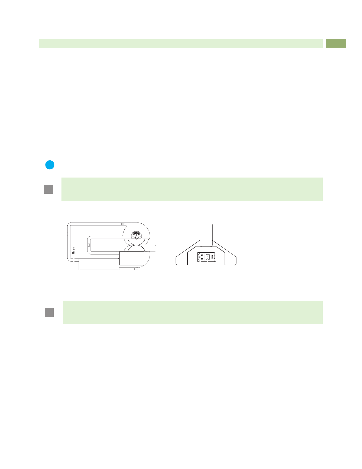
3.2 Connecting the Device
1
2 3 4
Fig. 3 Connections
3.2.1 Earthing Connection
!
Attention!
Hazard by electrical charge !
Provide an earthing connection via press stud (8).
3.2.2 Power Connection
1. Ensure that the device is switched off at the power switch (3).
2. Check the setting of the voltage selector (4).
• In order to alter the setting open the ap at the power input module.
• Remove the voltage selector (4) and re-insert it so that the correct voltage is visible when module the ap is
closed.
• Upon altering the setting, the fuses in the module must also be changed accordingly (T500 mA for 230 V; T1,0 A
for 115 V).
3. Connect the power cable to the power input module (2)
4. Connect the power cable to an earthed socket.
Page 8

8 8
3 Installation
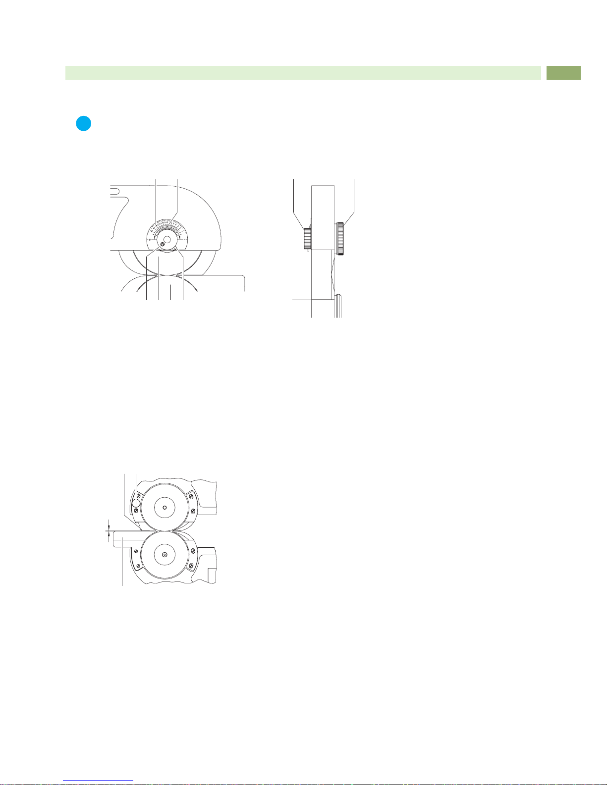
3.3 Height Adjustment of the Upper Blade
i
Notice!
Toavoidpossibledamageonthebladesduringtransporttheupperblade(4)isxedinthe"Parkposition"
so that there is a maximum distance to the lower blade.
Set the upper blade into the working position before switching on the machine.
4 53
1 2
3 6
Fig. 4 Height adjustment of the upper blade
There is a scale (1) on the frame where you can see the height adjustment in steps of 1/10 mm. When you receive
the machine, the pointer (2) of the scale is in position "16".
1. Hold the knob (3) and loosen the knurled knob (6).
2. Rotate the knob (3) clockwise until stop.
Through that the upper blade (4) move down to the lower blade (5) until both blades are just touching one another
(lower end position). Make a notice of the position of the pointer (2) to use it for all further adjustments.
This lower end position locks the upper blade in place to prevent it from moving out of adjustment.
3. Move the knob (3) anti-clockwise until the pointer is in the middle position between the lower end position and the
position "16".
4. Tighten the knurled knob (6).
5. Run some test-cuts to check if it is possible to separate the PCB's. If it is not possible reduce the distance
between the blades in small steps.
i
Notice!
The described adjustment helps to reduce the separation forces. This is important when sensitive components are very close to the groove.
!
Attention!
Before moving the machine to a new location, set the upper blade to the Park position.
Page 9
9
3 Installation
3.4 Adjustment of the Stop of the Upper Blade
i
Notice!
The lower stop of the upper blade adjustment is already adjusted by delivery.
After a long operation time, while working at strongly varying temperatures or else after replacing a
blade, it is recommended to re-adjust the lower stop.
1 2
4 53 6
7 8
Fig. 5 Adjustment of the stop of the upper blade
1. Hold the knob (7) and loosen the knurled knob (8).
2. Rotate the pointer (2) with the knob (7) anti-clockwise into position "16".
3. Loosen the cylinder screw (3).
4. Move the knob (7) clockwise until the upper and lower blades gently touch without overlapping.
5. Hold tight the knob (7) and tighten the knurled knob (8).
6. Swing the strut (6) clockwise until you reach the stop and tighten the cylinder screw (3). This adjustment locks the
upper blade in place to prevent it from moving out of adjustment.
7. Re-adjust the upper blade position 3.3 on page 8.
3.5 Upper Guide Adjustment
21
3
D
Fig. 6 Upper guide adjustment
1. Using a pre-scored PCB, check the clearance D between the guides (1,3). The clearance should be set so that
the edge of the upper guide is located correctly into the pre-scored groove of the PCB. The PCB can be smoothly
moved backwards and forwards but cannot move sideways.
The upper guide (1) prevent the PCB from slipping to the side and therefore ensures that it is not separated other
than at the pre-scored groove.
2. As required, the clearance D should be adjusted as described above by turning the eccentric adjusters (2).
Page 10

10 10
4 Operation
4.1 Switching on the Machine
Switch the machine on. The mains power switch (1) is situated at the rear of the machine in the mains module.
After switching on the display (2) of the control panel shows "0".
1
5
3
4
2
6
9
7
108
Fig. 7 Operation
4.2 Setting the Speed of Separation
i
Notice!
The speed may be switched during operation as well as in Standby mode. In the latter case, the set speed
will be shown as long as the SPEED key (3) is being pressed.
Press the SPEED key (3) if necessary several times. The key may be reached with a pointed tool through the
hole (4).
The speed may be adjusted in three levels: Display "1": 100 mm/s
Display "2": 200 mm/s
Display "3": 300 mm/s
4.3 Separating the PCB's
!
Warning!
Risk of hand injury !
Wear protective gloves while PCB separating.
i
Notice!
Whenusingthemachineforthersttime,degreasethebladeswithasoftcloth.
1. Press Start/Stop key (5).
The lower blade (10) starts to rotate at its preset speed. The preset speed will be shown at the display (2).
2. Lay the PCB (8) onto the lower guide (9).
3. Slide the PCB forwards between upper and lower guide (6,9) to the blades (7,10).
The rotating lower blade (10) will catch hold of the pre-scored PCB, which will be separated as it is transported
between the two blades.
4. In order to return to Standby mode, press the Start/Stop key. The motor will be switched off and the lower blade
will stop.
i
Notice!
When the machine is switched off, it is possible to separate PCB’s manually.
Insert the PCB between upper and lower guide (6,9) and then push it gently between the blades (10,11 ).
Page 11

11
4.4 Error Treatment
The device has an overload protection which will switch the motor off.
Error Message Cause Remedy
Display "F" Overload
• when trying to cut beside the prescored groove
• when a component on a PCB are
jammed between the blades
The cutter drive will perform a short backward
movement and will then switch off within 0.5 s of
the overload occurring. The backward movement
relieves the removing of the jammed material.
Remove the jammed material.
Press the Start/Stop key.
The device switches to the standby mode
(Display "0").
Check both blades for any possible damage
before re-starting operation.
Table 3 Error messages
1
5
3
4
2
6
Fig. 8 Alignment of blades and guides
!
Attention!
In order to ensure that the machine functions correctly, it is important that the surfaces of all parts shown
inthegure,ie.lowerguide(6),upperguide(3),andtheupperandlowerbladecovers(1,4)areexactlyin
line with the blades (2,5). This setting is achieved ex-works by placing washers between the machine frame
and the parts listed.
Only dismantle the above parts when absolutely necessary.
In such an event (eg. as a result of a very narrow side-strip removed from a PCB becoming jammed),
it is important that all washers removed are carefully put to one side. Upon reassembling the machine,
mount all parts with the concerning washers at the correct positions.
4 Operation
Page 12

12 12
5 Blade Replacement
Danger!
Unplug power cord before starting maintenance operation.
!
Warning!
Risk of hand injury !
Wear protective gloves while handling the blades.
1
5
3
4
2
6
11
8
10
7 9
12
Fig. 9 Blade replacement
5.1 Replacement of the Upper Blade
Spare Part: 8930509.001 Circular Blade
1. Raise the upper blade to the Park position.
2. Loosen the knurled knob (7) completely from the blade shaft (4).
3. Remove the circular blade (2) from the blade shaft (4).
Do not lose the spacers (1,5) located on the blade shaft (4), between the blade (2) and the frame. Replace the
spacers (1,5) if necessary.
4. Slide the replacement blade (2) onto the blade shaft as far as possible.
5. Put the knurled knob (3) onto the blade shaft.
6. Adjust the upper blade position 3.3 on page 8.
7. Adjust the stop of the upper blade 3.4 on page 9.
5.2 Replacement of the Lower Blade
Spare Part: 8933661.001 Circular Blade
1. Raise the upper blade to the Park position.
2. Unscrew the screw (9) from the shaft (10) and remove the clamping plate (8).
3. Remove the circular blade (12) from the shaft.
It will be found that between the blade and the housing, spacing washers (11) are located on the shaft. These
should be left on the shaft, or replaced as necessary.
4. Slide the replacement blade (12) onto the blade shaft as far as possible. Ensuring that the cut-out (7) in the blade
locates onto the key (6) on the blade shaft, slide the blade onto the shaft as far as possible.
5. Insert the screw (9) through the clamping plate (8) into the shaft.
6. Hold the blade (12) tight and tighten the screw (9).
7. Adjust the upper blade position 3.3 on page 8.
8. Adjust the stop of the upper blade 3.4 on page 9.
Page 13

13
6 Licences
6.1 EU Declaration of Conformity
cab Produkttechnik
GmbH & Co KG
Wilhelm-Schickard-Str. 14
D-76131 Karlsruhe
Deutschland
EU Declaration of Conformity
We declare herewith that the following device as a result of design, construction and the version put in circulation
complies with the relevant fundamental regulations of the EU Rules for Safety and Health. In the event of any alteration
which has not been approved by us being made to any device as designated below, this statement shall thereby be
made invalid.
Description: PCB Separator
Device: MAESTRO 2M
Applied EU-Directives and Standards:
Directive 2006/42/EC on machinery
• EN ISO 12100:2010
• EN ISO 13857:2008
• EN 349:1993+A1:2008
• EN 61029-1:2009+A11:2010
Directive 2014/30/EU relating to electromagnetic compatibility
• EN 61000-3-2:2014
• EN 61000-3-3:2013
• EN 61000-6-2:2005
• EN 61000-6-4:2007+A1:2011
Directive 2011/65/EU on the restriction of the use of certain
hazardous substances in electrical and electronic equipment
• EN 50581:2012
Person authorised to compile the technical le: Erwin Fascher
Am Unterwege 18/20
99610 Sömmerda
Signature for the producer:
cab Produkttechnik Sömmerda
Gesellschaft für Computerund Automationsbausteine mbH
99610 Sömmerda
Sömmerda, 04.10.2017
Erwin Fascher
Managing Director
Page 14

14 14
6.2 FCC
NOTE: This equipment has been tested and found to comply with the limits for a Class A digital device,
pursuant to Part 15 of the FCC Rules. These limits are designed to provide reasonable protection against
harmful interference when the equipment is operated in a commercial environment. The equipment
generates, uses, and can radiate radio frequency and, if not installed and used in accordance with the
instruction manual, may cause harmful interference to radio communications. Operation of this equipment in
a residential area is likely to cause harmful interference in which case the user may be required to correct the
interference at his own expense.
6.3 ICES-003
This Class A digital apparatus complies with Canadian ICES-003.
Cet appareil numérique de la classe A est conforme à la norme NMB-003 du Canada.
6 Licences
Page 15

15
7 Index
C
Circular blade
...................................12
Connecting
.........................................7
Contents of delivery
............................7
E
Earthing
..............................................7
Environment
.......................................4
Error messages
................................11
Error treatment
.................................11
I
Important information..........................4
Intended use
.......................................4
L
Lower Blade
Replacement
...............................12
P
Power supply
......................................4
Power switch
....................................10
Protective gloves
........................10, 12
R
Recycling
............................................5
Replacement blades
.........................12
S
Safety instructions
..............................4
Separating the PCB's
.......................10
Separation forces
...............................8
Separation speed
.............................10
Service work
.......................................5
Setting-up
...........................................7
Specication
.......................................6
Switching on
.....................................10
T
Technical Data
....................................6
U
Unpacking...........................................7
Upper blade
Height adjustment
.........................8
Replacement ...............................12
Stop
..............................................9
Upper guide
........................................9
V
Voltage................................................4
Voltage selector
..................................7
W
Warning stickers
.................................5
 Loading...