

CAB MACH 4.3S/300C, MACH 4.3S/200C, MACH 4.3S/200P, MACH 4S/300P, MACH 4S/300C Service Manual
...Page 1

Made in Germany
Service Manual
MACH 4S
Label Printer
Page 2

2 2
Family Type
MACH 4S - MACH 4.3S/200B
- MACH 4.3S/200P
- MACH 4.3S/200C
MACH 4S/300B MACH 4.3S/300B
MACH 4S/300P MACH 4.3S/300P
MACH 4S/300C MACH 4.3S/300C
MACH 4S/600B MACH 4S/600P MACH 4S/600C -
Edition: 12/2017 - Part No. 9003102
Copyright
This documentation as well as translation hereof are property of
cab Produkttechnik GmbH & Co. KG.
The replication, conversion, duplication or divulgement of the
whole manual or parts of it for other intentions than its original
intended purpose demand the previous written authorization by
cab.
Editor
Regarding questions or comments please contact cab
Produkttechnik GmbH & Co. KG.
Topicality
Due to the constant further development of our products
discrepancies between documentation and products can occur.
Please check www.cab.de for the latest update.
Terms and conditions
Deliveries and performances are effected under the General
conditions of sale of cab.
Service Manual
for the following product
Germany
cab Produkttechnik
GmbH & Co KG
Postfach 1904
D-76007 Karlsruhe
Wilhelm-Schickard-Str. 14
D-76131 Karlsruhe
Telefon +49 721 6626-0
Telefax +49 721 6626-249
www.cab.de
info@cab.de
France
cab technologies s.a.r.l.
F-67350 Niedermodern
Téléphone +33 388 722 501
www.cab.de/fr
info.fr@cab.de
USA
cab Technology Inc.
Tyngsboro MA, 01879
Phone +1 978 649 0293
www.cab.de/us
info.us@cab.de
Asia
cab Technology Co., Ltd.
Junghe, Taipei, Taiwan
Phone +886 2 8227 3966
www.cab.de/tw
info.asia@cab.de
China
cab (Shanghai)Trading Co., Ltd.
Phone +86 21 6236-3161
www.cab.de/cn
info.cn@cab.de
Representatives in other countries on request
Page 3

3
1 Introduction ............................................................................................................................................4
1.1 Instructions ...............................................................................................................................................4
1.1 General Safety .........................................................................................................................................5
1.2 Safety Markings .......................................................................................................................................5
1.3 Handling Electricity ..................................................................................................................................6
1.4 Conduct during Accidents ........................................................................................................................6
2 Changing Assembly Parts .....................................................................................................................7
2.1 Tools .........................................................................................................................................................7
2.2 Changing the Control Panel .....................................................................................................................7
2.3 Dismounting the Cover .............................................................................................................................8
2.4 Changing the Print Mechanism ................................................................................................................9
2.5 Changing the Printhead .........................................................................................................................10
2.6 Changing the Print Roller .......................................................................................................................12
2.7 Changing the Clutch and Brake of the Ribbon Rewinder .......................................................................13
2.8 Changing the Brake of the Ribbon Unwinder .........................................................................................14
2.9 Changing the Drive of the Cutter ............................................................................................................15
2.10 Changing the Blade of the Cutter Unit ...................................................................................................16
2.11 Changing the Circuit Board ....................................................................................................................17
2.12 Changing the Power Supply ...................................................................................................................18
3 Adjustments .........................................................................................................................................19
3.1 Measuring the Winding Force ................................................................................................................19
3.1.1 Testing the Winding Force of the Clutch and Break of the Ribbon ...................................................19
3.1.2 Measuring the Breaking Force of the Unwinder ...............................................................................20
3.2 Setting the Winding Force ......................................................................................................................21
3.3 Adjusting the Print Mechanism ...............................................................................................................22
3.3.1 Adjustable Elements .........................................................................................................................22
3.3.2 Settings.............................................................................................................................................23
4 Troubleshooting and Error Treatment ................................................................................................24
4.1 Failure of Device Functions ....................................................................................................................24
4.2 Permanently Occurring Hardware Errors ...............................................................................................24
5 Block Diagram ...................................................................................................................................... 25
6 Layout Diagram PCB CPU ................................................................................................................... 26
7 Index ......................................................................................................................................................27
Table of Content
Page 4

4 4
1.1 Instructions
Important information and the instructions in the documentation are designed as follows:
Danger!
Draws attention to an exceptionally great, imminent danger to your health or life due to hazardous
voltages.
!
Danger!
Draws attention to a danger with high risk which, if not avoided, may result in death or serious injury.
!
Warning!
Draws attention to a danger with medium risk which, if not avoided, may result in death or serious injury.
!
Caution!
Draws attention to a danger with low risk which, if not avoided, may result in minor or moderate injury.
!
Attention!
Draws attention to potential risks of property damage or loss of quality.
i
Note!
Advices to make work routine easier or on important steps to be carried out.
Environment!
Gives you tips on protecting the environment.
Handling instruction
Reference to section, position, illustration number or document.
Option (accessories, peripheral equipment, special ttings).
Time Information in the display.
1 Introduction
Page 5
5
1.1 General Safety
This service manual is intended for qualied service and maintenance personnel. Further information to the operation
of the device can be found the Operator's and Conguration Manuals.
The following rules are for your general safety
• Keep the area during and after maintenance operations clean.
• Work safety conscientious.
• Keep dismounted parts secure during maintenance operations.
• Avoid tripping hazards.
N
Danger!
Double-pole or neutral conductor safety.
Danger!
Danger of electrocution wenn stronger currents are used by connected metallic parts.
Do not wear clothing with metal.
Do not wear jewelry.
Do not wear glasses with a metal frame.
!
Warning!
Loose clothing can get caught in rotating parts of the device and can lead to injury.
When operating the device avoid wearing clothing that can get caught in rotating parts.
1.2 Safety Markings
!
Warning!
Waring of injury due to missing or damaged safety markings.
After maintenance operations reapply all protective parts, markings, covers, grounding cables, etc.
Replace all defective or damaged parts.
Wear safety goggles when:
• knocking in or out pins or similar parts with a hammer
• using spring hooks
• installing or removing springs, safety rings gripping rings
• using abrasive, cleaners, solution or other chemicals
1 Introduction
Page 6

6 6
1 Introduction
1.3 Handling Electricity
The following operations may only be performed by qualied electricians:
• Any labor performed on electrical component groups.
• Operations performed on the opened device while it is connected to the power grid.
General precautions when commencing maintenance operations:
• Locate the emergency power and/or mains switch so it is reached quickly should the need arise.
• Disconnect the power when performing the following tasks:
- Removing or installing the power supply.
- Performing work in the vicinity of opening power connectors.
- Mechanical testing of power units.
- Altering anything to do with the circuitry.
• Check that the device is not live.
• Check the work area for any potential hazards such as damp or wet oors, defective extension cords or protective
conductors.
Additional precautions when dealing with open voltage supply:
• Request a second person to stay in the vicinity and operate the emergency powers or mains switch if and when
required.
• Only use one hand when working with electronic circuits. Keep the other hand behind your back or in a pocket. By
doing so you prevent electricity from owing though the body.
1.4 Conduct during Accidents
• Act with exception caution and calmness.
• Do not put yourself at risk.
• Switch off the power.
• Request medical assistance or call an emergency doctor.
• If required and possible perform rst aid.
Page 7
7
2 Changing Assembly Parts
2.1 Tools
• Do not use worn or damaged tools.
• Only use tools and test devices for their designed purposes.
Specialized tools(cab in-house produced):
• Test devices ribbon holders (cab part no.: 5540932)
• Assembly assistance coupling (cab part no.: 5541180)
• Cylindrical dynamometer (spring scale), 0 - 10 N (cab part no.: 5906108)
Commercial tools:
• Torx screwdriver, size TX 10/200
• Allen wrenches straight, size 2,5
• Screwdriver with parallel shaft, size 4
• Flat nose pliers
2.2 Changing the Control Panel
i
Note!
When changing the control panel B or P to a control panel C (exchange to measurement version) the
dispensing edge must be removed from the device. When changing the to the other panels the dispensing
edge must be mounted. ( 2.6 on page 12).
3
2
1
4
5
2
3
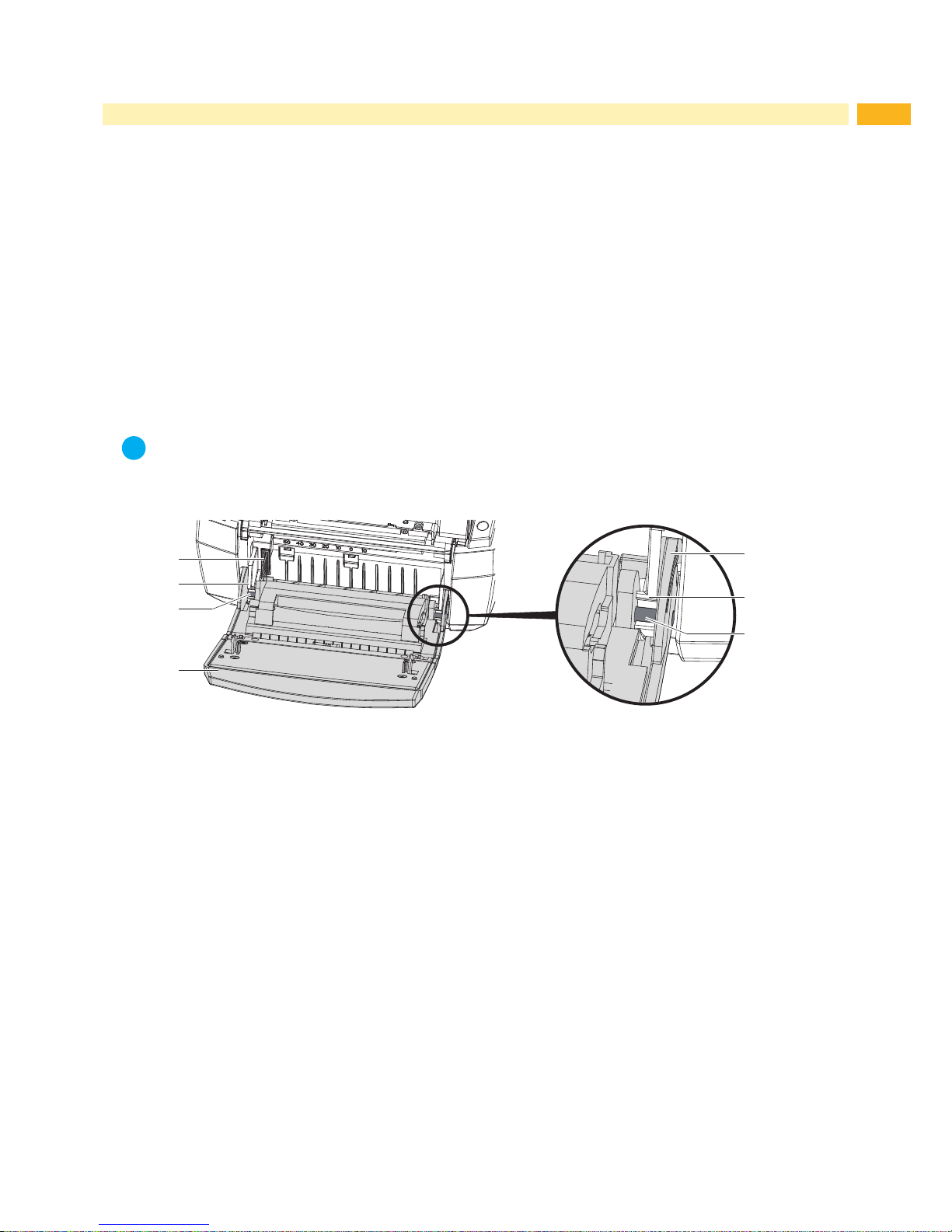
Fig. 1 Changing the control panel
1. Fold the control panel (4) down.
2. Steady the device with one hand and pull the control panel along axis (3) sturdily, releasing it from its retainer (2).
3. Take hold of the control panel over the second axis and pull it until it is released from its retainer.
4. Guide the brackets (5) next to the retainers (2) out of the device.
5. Disconnect the connector (1) from the printer and set aside the control panel.
6. Connect the connector (4) of the new control panel to the printer.
7. Guide the brackets (5) along the side of the retainers (2).
8. Lift the control panel a little.
9. Push the control panel rmly into the axis (3) of the retainer (2) until you hear the axis snap into the retainer.
Page 8

8 8
2 Changing Assembly Parts
2.3 Dismounting the Cover
Danger!
Risk of death by electrocution.
Before opening or dismounting the cover disconnect the device from the power grid and wait at least
one minute until the device has discharged.
1
1
1
2
3
1
Fig. 2 Dismounting the cover
The printer cover can be dismounted completely including the front lid.
1. Open the printer cover (2) and remove the roll and material retainer.
2. Loosen 4 screws (1)
3. Remove the cover (3) with the lid (2)
To mount the cover and lid follow the above order in reverse. To make the implementation of the parts easier fold the
printing modules up.
Page 9

9
2 Changing Assembly Parts
2.4 Changing the Print Mechanism
Danger!
Risk of death by electrocution.
Before opening or dismounting the cover disconnect the device from the power grid and wait at least
one minute until the device has discharged.
6
1
2
3
4
5632
7
8
9
Fig. 3 Changing the print mechanism
1. Dismount the control panel ( 2.2 on page 7).
2. Dismount the printhead ( 2.5 on page 10).
3. Dismount the cover ( 2.3 on page 8).
4. Disconnect the cables (4) connecting the printing mechanism to the CPU circuit board.
5. Disconnect the ground wire (6) from the from CPU circuit board by undoing the screw (5).
6. After loosening the two screws (2) slide and raise the print mechanism backwards until it, with the screws (2), can
be lifted out of the adjustment slots (7).
7. Slide the new printing mechanism with the bracket (9) into the guides (8). Place the adjustment slots (7) onto the
screws (2) pushing the unit forward until the indentations (3) snap into their counterparts (6).
8. Fasten the screws (2).
9. Fasten the ground wire (6) to the CPU circuit board with screw (5).
10. Connect cables (4) to the CPU circuit board.
11. Mount the cover and lid ( 2.3 on page 8).
12. Mount the printhead ( 2.5 on page 10).
13. Mount the control panel ( 2.2 on page 7).
Page 10

10 10
2.5 Changing the Printhead
Changing a printhead can be completed without ne adjustments to the printer. Changing the printhead is necessary
when it is worn or a change of printing resolution is needed.
1
2
3
3
4
1 Connector data
2 Connector power
3 Threaded holes
4 Heating element
Fig. 4 Assembly of the printhead
!
Attention!
Damaging the printhead by electrical discharge or mechanical inuences!
Set up the printer on an grounded conduit.
Ground yourself with e.g. an anti static bracelet.
Do not touch the connectors (1, 2).
Do not touch the heating element (4) with hands or hard objects.
2 Changing Assembly Parts
Page 11

11
2 Changing Assembly Parts
5
6
7
986
12 13 126 161514 14
10 1011
Fig. 5 Changing the printhead
Removing the printhead
1. Open the cover and fold the control panel (7) down. Push the energy regulator (5) and fold the printing module up
with the printhead retainer (6).
2. Take the material out of the printer.
3. Push against the printhead retainer (6) from underneath, lifting the mounting bracket (9) over the bar (8) and then
down through the slit.
4. Pull the printhead retainer (6) out of the guide (11) of the printing module.
5. Remove the printhead (13) by undoing the screws (12) of the printhead retainer (6).
6. First remove the power cable (16) and then the data cable (15).
Installing the printhead
7. Connect the data cable (15), then the power cable (16) to the new printhead.
8. Fasten the printhead (13) with the screws (12) to the printhead retainer (6).
9. Place the printhead retainer (6) with the loop into the guide (11) and push it upward against the springs (10) where
the springs should land on the indentations (14). Guide the mounting bracket (9) through the slit towards the top
and over the bar (8) until it locks in place.
10. Install the material once more, close the control panel and cover before use.
!
Attention!
If there is a loss of quality visible on the printed label after the exchange of the printhead adjustments need
to be performed. 3.3 on page 22.
Page 12

12 12
2 Changing Assembly Parts
2.6 Changing the Print Roller
1 2 3
6 5
4
Fig. 6 Changing the print roller
1. Open the cover and fold the control panel down. Push the unlocking mechanism and fold the printing module up.
2. Through the openings on both sides, push the pressure points (1) until the print roller assembly (2) snaps out of
the locking mechanism. This action lifts the print roller assembly (2) a little.
3. Lift the unlocked pressure roller assembly (2) out of the device.
4. Remove the roller locking mechanism (6) from the print roller (5) and remove the dispensing edge (3) from the
roller locking mechanism (4).
5. Insert the dispensing plate (3) into the roller locking mechanism (4) of the new print roller and push the new roller
locking mechanism (6) onto the print roller and the dispensing edge.
!
Attention!
When exchanging the control panel B or P with control panel C ( 2.2 on page 7) the dispensing edge
must be removed prior to the exchange.
Connect the roll retainer (5) to the pressure roller (4) and place the assembly group, without the
dispensing edge (3), into the printer.
Follow the reverse order to achieve the opposite effect.
4. Insert the pressure roller assembly group (2) into the printer and evenly push down to lock it into place.
5. Lock the printing and control modules.
Page 13

13
2 Changing Assembly Parts
2.7 Changing the Clutch and Brake of the Ribbon Rewinder
The clutch (4) is a pre-constructed assembly group, the brake consists of the form disks (5, 7), the friction disk (6)
and three springs (9).
21
3
4
5
6
7
8
9
11
10
Fig. 7 Changing the clutch and brake of the ribbon rewinder
Dismounting
1. Fold up the printhead assembly group, loosen the three screws (2) and lift off the cover (1).
2. Close the printhead assembly group and lay the printer on its side.
3. Undo the snap ring (3) and remove clutch (4), form disks (5, 7), friction disk (6), springs (9) and tension wheel
(11).
Mounting
1. Place the springs (9) into the frame (10).
2. Place and hold the tension wheel (11) into the frame.
3. Set the form disks (7) in line with the retainers (8) of the frame.
4. Place the friction disk (6), form disks (5) and clutch (4) as illustrated.
5. Push the clutch and tension wheel against the frame and fasten the snap ring (3) on the axis of the tension wheel
(11).
6. Check the winding torque ( 3.1 on page 19) and correct the settings as necessary. ( 3.2 on page 21).
7. Fold the printhead assembly up and fasten the cover (1) with the three provided screws (2).
Page 14

14 14
2 Changing Assembly Parts
2.8 Changing the Brake of the Ribbon Unwinder
321
8654 7
5 6 7109 11 11 10 9 12
Fig. 8 Changing the brake of the ribbon unwinder
1. Fold up the printhead assembly group, undo the three screws (3) and remove the cover (2).
2. Insert the ribbon retainer (1).
3. Unhook the spring (4) from the pivot arm (5).
4. Hold the ribbon retainer (1), guide the pin of the mounting assistance (8 / Part No. 5541180) into the two allocated
spaces of the retainer (6). Push the mounting assistance against the printhead assembly group and turn it
counter-clockwise until the lock washer (7) releases and can be taken out.
5. Take off the retainer (6), spring (12), from disks (9, 11), friction screw (10) and pivot arm (5).
6. Set the new parts according to the illustration.
!
Attention!
Place the lock washer (7) with its markings to the outside.
7. Turn the lock washer (7) with the mounting assistance (8) clockwise until it locks into place.
8. Clip the spring (4) to the pivot arm (5).
9. Check the winding torque ( 3.1 on page 19) and adjust the settings it if necessary. ( 3.2 on page 21).
10. Fasten the cover (2) with the three screws (3) provided.
Page 15

15
2 Changing Assembly Parts
2.9 Changing the Drive of the Cutter
2 3 85 64 7
32
1
9 10 11 12 10 9
Fig. 9 Changing the drive of the cutter
1. Fold down the control panel (1), release the cutter (4) from the brackets (3) and fold this up too.
2. Unhook the springs (3).
3. Disconnect the plug (7).
4. Undo and remove the nuts (11), screws (9) with connecting rods and bearings.
5. Unlock the eccentric (10) from the shaft (6).
6. Lift out shaft (6) with the drive (8) from the base plate (12).
7. Pull the drive (8) from shaft (6).
8. To reconstruct the assembly follow these instructions in the reverse order. Place the drive into the adjustment slot
of the base plate (10).
!
Attention!
Align the pins of the eccentric (10) to the clock wheel (5) as illustrated.
Page 16

16 16
2 Changing Assembly Parts
2.10 Changing the Blade of the Cutter Unit
2 3 74 5 6
2
1
8 9 10 1211
Fig. 10 Changing the blade of the cutter unit
!
Danger!
Danger of lacerations!
Do not touch the blade without protective measures.
1. Fold down the control panel (1).
2. Release the cutter unit (3) by undoing the brackets (2) and fold it upwards.
3. Loosen the three screws (4) and the washers (5) and remove the bottom blade.
4. Loosen the three screws (8) and take off the top blade and the material guide (10).
5. Screw a new top blade and paper guide (11) to the base plate.
6. Screw a new bottom blade to the bracket (12).
i
Note!
If only the top blade (9) needs to be replaced the camp (12) with the bottom blade (6) can be hinged up from
the top blade by turning the screw (7) with a hexagonal key 2.5 mm.
!
Danger!
Danger of lacerations and crushing limbs!
While folding the panel up or down particularly when the panel is folded down the springs at the clamp
are under high tension. Do not reach between the blades.
Page 17

17
2 Changing Assembly Parts
2.11 Changing the Circuit Board
Danger!
Danger of electrocution.
Before opening the pinter cover disconnect the device from the power source and wait at least one
minute until the device has discharged the remaining residual energy.
2
1
2
3
2
4
9
5
6
28
7
1 Circuit board CPU
2 4 Screws
Connections
3 CON8 - stepper motor
4 CON9 - power supply
5 CON10 - printhead
6 CON11 - sensors
7 CON12 - control panel
8 Ground wire
9 CON13 - Ventilator
Fig. 11 Changing the CPU circuit board
1. If possible save the printer conguration onto an external memory medium Printer conguration.
2. Disconnect the printer from the power supply.
3. Disconnect all interface cables from the back of the printer.
4. Remove all removable storage mediums.
5. Remove the printer cover ( 2.3 on page 8).
6. Disconnect all push on connectors (3-7, 9) from the CPU circuit board.
7. Remove the four screws (2) of the circuit board.
8. Insert the new CPU circuit board (1) with the previous four screws (2) whilst connecting the ground wire (8).
9. Reconnect all the push on connectors (3-7, 9) to the circuit board.
10. Reassemble the cover ( 2.3 on page 8).
11. Reconnect all interface cables from the back of the printer.
12. Reestablish the power connection.
13. If required, guide the device through an update.
14. Synchronize the light barrier Conguration Manual.
15. If possible, load the settings from the removable storage device via the control panel Conguration Manual.
Page 18

18 18
2 Changing Assembly Parts
2.12 Changing the Power Supply
Warning!
Risk of death by electrocution!
Before opening the cover plate remove the device from the power supply and wait at least one minute
until the residual energy has dissipated.
1
2 2
2 3
Fig. 12 Changing the power supply
1. Remove the printer from the power supply.
2. Dismount the cover with the lid ( 2.3 on page 8).
3. Remove the CPU circuit board ( 2.11 on page 17).
4. Pull off the push on connectors (3).
5. Undo three screws (2).
6. Dismount the power supply (1).
7. Insert the new power supply (1) and fasten it with screws (2).
8. Connect the push on connector (3).
9. Reassemble the CPU circuit board.
10. Reconnect the cover and lid.
Page 19

19
3 Adjustments
3.1 Measuring the Winding Force
The measurement of the un- and re-winding torque of the ribbon is determined by the tensile force on the test
material that is connected to the ribbon retainer.
The physical connection between the torque and tensile force is as follows.
F= M / r
F: force [N],
M: torque [Ncm],
r: Radius of the test material (30 mm)
3.1.1 Testing the Winding Force of the Clutch and Break of the Ribbon
1
2
A B
C
3
1
2 3
1
2 3
Fig. 13 Testing the winding torque of the clutch and break.
Target Value Measurement Torque M Force F
Clutch of the rewinder ribbon A 14,4 - 17,4 Ncm 4,8 - 5,8 N
Break of the rewinder ribbon B 2,7 - 4,5 Ncm 0,9 - 1,5 N
1. Place the test device (3) on the ribbon retainer (2). Note that the Spring tip must be placed in the grove of the
ribbon retainer for a true result.
2. Close the printhead assembly group and employ the spring scale connecting it to the rewinder with the test device
(3) inserted.
3. To measure the clutch force wind the string around the test device (3) numerous times as illustrated in A.
4. Connect the spring scale [10 N] (1) to the end of the string and move it upwards vertically until the test device
starts to turn.
5. Unravel the string at least one full revolution of the test device and measure the force F of the clutch from the
spring scale.
6. If the torque deviates from the target values set it anew. ( 3.2 on page 21).
7. To measure the breaking force wind the string around the test device (3) numerous times as illustrated in B and
repeat the process.
8. If the force of the breaking force deviates from the target values the break need to be replaced as there are no
settings possible. ( 2.7 on page 13).
Page 20

20 20
3 Adjustments
3.1.2 Measuring the Breaking Force of the Unwinder
C
1
2 3
Fig. 14 Measuring the breaking force of the unwinder
Target Value Measurement Torque M Force F
Break of the unwinder ribbon C 3,9 - 4,5 Ncm 1,3 - 1,5 N
1. Insert the test device (3) onto a ribbon retainer (2). Note that the Spring tip must be placed in the grove of the
ribbon retainer for a true result.
2. Open the printhead assembly group and insert the ribbon retainer (2) with the inserted test device (3) onto the
rewinder.
3. To measure the breaking force wrap the string around the test device (3) as illustrated in C.
4. Connect the spring scale [10 N] (1) to the end of the string and pull it upwards vertically until the test device starts
to turn.
5. Pull until the test device complete a full revolution and measure the force F of the break.
6. If the results deviate from the target values change the settings.( 3.2 on page 21).
Page 21

21
3.2 Setting the Winding Force
8765
1 2 3
4
Fig. 15 Setting the winding force
The settings of the winding force of the break (5) of the unwinder and the clutch (6) of the rewinder is done in the
same way.
1. Insert the ribbon retainer (4) onto the winders.
2. Fold the printhead assembly group up and undo the three screws (8) and remove the cover (7).
3. Hold the ribbon retainer, push holder (2) towards the frame (1) turning it to the desired position and let go, taking
note that the straps of the locks (3) are all the way in the provided gaps.
4. Test the winding force again and compare it to the these to the test values and correct if necessary.
5. refasten the cover (7) with three screws (8).
i
Note!
The numbers of the retainer (2) are not setting values. They are an orientation when setting the winding
force.
1: smallest winding force, 7: largest winding force
3 Adjustments
Page 22

22 22
3 Adjustments
3.3 Adjusting the Print Mechanism
Changing the settings of the printing mechanic over and above a format change is only necessary when something
other than the printhead is exchanged or if the printhead assembly group has been demounted or altered.
The following identiers point towards resetting the printing mechanic:
- Printed image too light
- Printed image blotchy or spotty
- Printed image too light on one side
- Horizontal lines not parallel to the to the label edge
- Clear sideways drift of the ribbon
i
Note!
Check the ribbon as creases in it may cause image errors.
3.3.1 Adjustable Elements
2 3 1
4 5
1
6 6
Fig. 16 Adjustable elements
Screws for horizontal settings (1)
- Turning the screw clockwise will move the printhead forward.
- Turning the screw counter clockwise will move the printhead backwards.
For an optimal image the heat element must be set to align to the highest point of the pressure roller. In this position
the print image blackening is at its best. Besides that this setting allows the realignment of horizontal lines with the
dispensing edge.
Screws for setting the printhead (6)
- Turning of the screws in a clockwise fashion lessens the printhead pressure to the corresponding side.
- Turning the screws counter clockwise increase the pressure.
Increasing the pressure of the print by turning screw (6) counter clockwise will darken the image on the corre-
sponding side and shift the ribbon ow toward the opposite side.
!
Attention!
Turn the screw (6) counter clockwise carefully as an excess will demount parts completely.
Page 23

23
3 Adjustments
Screw for adjusting the camber (3)
- By turning the screw clockwise the printhead will be changed minimally in the center causing pressure in the
middle of the printhead.
If all else fails to decrease creases in the ribbon the printhead can be altered by turning the screw clockwise. It is
recommended to proceed with the utmost caution when performing these alterations.
!
Attention!
Danger of causing damage to parts of the device.
As soon as there is a distinguishable resistance when turning the screw do not turn it more than another
90°.
The result is that the image will be lightened along the outside edges of the image compared to the middle.
3.3.2 Settings
1. Insert material (labels and ribbon) that covers the entire printing width.
2. Congure the printer to heating power 0 and printing speed 100 mm/s.
3. Turn the camber screw (3) counter clockwise until the resistance subsides. This should be about half a revolution.
4. Undo screw (2) and by turning screw (1) align the marking (4) to the middle segments (5) of the graduation.
5. Perform test prints with "test grid" labels or the like.
6. If the horizontal lines of the test grid are not parallel to the label edge adjust the alignment with screw (1).
7. Use screw (6) to adjust the printhead pressure. Turn the screw only until turning becomes easier.
8. Reduce the heat of the heating element so far that the printed image is light. By doing misalignments become
easy to spot.
9. Test via a grind print increasing the pressure of the side of the printhead where the image is lighter. This is
achieved by turning the screw (6) counter clockwise by about a quarter revolution or until the printed image
appears evenly printed.
10. Turn screw (1) counter clockwise and push the printhead backwards until the printed image almost disappears.
Now turn screw (1) clockwise until the image has reached it darkest value. Take note of the horizontal alignment.
11. Fasten screw (2).
12. Check the ribbon uptake. If the ribbons runs to the right turn the right screw (1) by a quarter revolution counter
clockwise. If the ribbon runs left turn the left screw (1) counter clockwise by a quarter revolution. Test the ribbon
uptake after every adjustment and wait until it has stabilized before attempting further adjustments.
13. In the case of creasing on both edges simultaneously adjust the camber of the printhead. For this carefully turn
the screw (3) clockwise. Turn this screw as little as possible. A slight decrease in printing strength of the image
may be expected.
!
Attention!
Danger of causing damage to the device.
As soon as there is a distinguishable resistance when turning the screw do not turn it more than another
90°.
14. If there is no camber adjustment necessary turn screw (3) clockwise until it clamps down minimally.
15. Turn down the heating energy in the conguration to 0 and test these results of the previous adjustments. With
normal cab-standard material a clearcut, solid black printed image should have been achieved.
Page 24

24 24
4 Troubleshooting and Error Treatment
4.1 Failure of Device Functions
Function error Possible solutions
No material transport Check electronic connection between the CPU circuit board and the motor
Check the drive mechanism
Exchange the CPU circuit board
Exchange the motor
No printed image at material
transport
Check connectors of the printhead
Inspect the printhead cable for damage
Exchange the printhead
Exchange the CPU circuit board
Display does not work Check the cable connection between the CPU circuit board and the control panel
Swap out the display
Exchange the CPU circuit board
No communication over the
interface
Check the connection from the printer to the computer
With Ethernet connections check the validity of the IP address and the subnet
mask.
Check, and if necessary change, the interface cable
In case of complete outage exchange the CPU circuit board
A peripheral device does not
work
Check if the peripheral device is connected via programming
Ensure the USB cable of the peripheral device is working and exchange it if
necessary
Test the peripheral device
Exchange the CPU circuit board
Table 1 Failure of device functions
4.2 Permanently Occurring Hardware Errors
Error message Cause Solution
Printhead thermistor defect
Thermistor of the printhead
broken
Exchange the printhead
Voltage error
V
BAT
Voltage of the battery on the
CPU circuit board too low
Exchange the CPU circuit board
24 V
24 V too little Check voltage at measuring point +24V
Fig. 18 on page 26:
• Voltage too low:
Swap out power supply
• Voltage sufcient:
Exchange the CPU circuit board
24 V TPH
24 V too low for printhead Check voltage at measuring point +24V TPH
Fig. 18 on page 26:
• Voltage too low:
Swap out power supply
• Voltage sufcient:
Exchange the CPU circuit board
Table 2 Hardware errors
Page 25

25
5 Block Diagram
Printer Nr.1
MACH 4S/300... 5977444
MACH 4S/600... 5977380
MACH 4.3S/200... 5977382
MACH 4.3S/300... 5977383
Fig. 17 Block diagram
Page 26

26 26
6 Layout Diagram PCB CPU
1
L6
12
R130
L57
C185
R323
B6
22
C391
R37
P6
R131
R33
R159
2
R304
V19
1
G
B
+
C13
K
R61
R220
V11
G
X1
V
M
R305
TOP21
N
R22
C14
R268
L27
1
V1
R64
L12
AC
C16
V18
9
C205
C208
10
R270
C341
L
B3
A1
C73
C255
20
C211
4
R169
5
C192
C256
L43
L15
C214
1
R70
1
15
C246
C193
+
C215
V12
A
A
P9
N6
TOP25
C259
R96
C194
L
C216
E
C26
D
L21
K
TOP16
AA
C264
R
D4
C217
U1
V24
T
R97
V15
L60
C272
L50
3
C224
C221
TOP7
R60
D
L70
L61
C262
13
C276
CON1
C223
R170
P
K1
23
R1
L62
R140
C17
C279
C201
8
L31
C289
R84
4
K
L63
C8
C280
U7
18
C202
CD
R107
R126
C6
C
C10
3
1top
WP
C203
C232
1
R141
U8
C
K
TOP11
P
R89
H
R4
C11
Buchse
L29
TOP5
H
C210
N
R72
AE
R68
R65
T
C235
L83
R237
W
R5
C212
C291
2
R74
R42
R73
L5
6
G
1
C242
C292
1
R168
R122
TOP26
16
L13
C234
#FD2
Gn
25
C282
C324
R99
F1
C240
11
TOP17
C286
L73
R213
21
P5
L3
V14
A
2
F
R19
9
C243
C321
+
E
R119
R219
F
TOP1
U
L
L56
M
R56
R120
D3
L64
R87
AB
C252
R572
TOP20
C198
8
L53
C12
9
R88
R25
L10
K
R573
C200
19
R100
R574
R48
4
L37
L24
R101
B2
N5
D15
14
R575
CON10
L38
TOP14
24
D2
P8
2
1
R47
1
R137
TOP9
J
R568
R116
D
TOP4
C153
C
R27
U3
J
R66
C263
D13
Y
C342
C113
P
F2
K
R571
C154
R
R29
L48
R69
TOP15
C270
C314
2
L2
C348
C155
C
L18
C265
12
C116
R102
N
R6
K2
TOP23
C156
22
C293
L71
L33
3
C148
C260
R121
C266
C152
7
C1
L51
C149
C320
CON2
17
L93
P2
R142
C161
R132
L34
C9
L39
C258
B
U2
2
C184
GND
R123
R256
R35
CON12
C162
A
R59
B
N
R117
G
R215
1
R75
C261
G
R125
L68
M
C2
C28
C163
AC
D14
R71
CON4
R108
V
R136
C187
C307
R166
1
L90
V13
V7
C164
C5
5
R280
F
R77
C308
L25
R160
C213
C160
15
C207
2
R253
V21
R139
C42
C204
1
R163
C169
L42
L80
TOP6
C268
CON17
10
C15
R209
R78
C271
3
L14
#FD3
C170
N1
R98
C196
20
1
P4
CON9
C225
C209
C309
1
U4
R171
L66
H1
R31
C171
K
8
L1
C313
25
R85
E
C310
T
R172
K
B5
C27
C351
C172
R150
L30
C352
L
R2
C325
C220
C311
L59
R227
V9
C168
AA
C112
7
R58
R303
R3
C302
C312
C158
8
C183
C175
R158
J
TOP19
C199
C267
V10
18
C304
K
C345
C159
R254
L9
C180
C176
L58
C206
3
V20
2
C322
C346
C166
R255
E1
C181
C177
13
C3
N4
C323
C347
C167
23
V25
R20
R245
P7
C182
C178
R23
B1
C285
14
H
R76
C
C349
C114
TOP22
G2
R247
CON5
C150
C174
B
R62
R26
H
C4
W
N
L16
V2
C230
C237
C350
R41
P
L28
R566
V17
C151
R63
H7
B4
C283
C335
AD
C231
C239
R567
B
C222
R301
TOP13
11
D5
M
L89
R155
A2
H4
L17
TOP8
21
1
C338
C275
L72
L40
C241
1
D1
6
R298
C186
C327
L74
C274
C339
L49
TOP3
16
C245
P1
TOP24
C278
H5
E
C340
1
1bot
GND
1
L20
G6
C300
R299
C288
C66
M
F
R24
F
L
CON3
CON11
AB
C303
H6
C77
C343
U
R11
L69
L67
A
R294
R300
R55
C157
4
C344
1
E
2
14
C301
TOP12
C165
C290
L23
R
1
L36
24
R134
C277
C197
+
C173
C296
L75
R236
9
1
C295
R109
R36
C179
19
C297
P3
L87
L32
R295
R44
N2
1
D
7
C219
AE
D
R
L35
L84
J
R45
R32
N3
J
C287
#FD1
P
AD
TOP2
1
Y
R34
C269
K
CON8
L26
C299
3
C72
7
R30
R151
H
R569
R54
L4
V3
CON7
17
R21
1
T
Ye
TOP10
R111
R152
TOP18
2
R570
L52
L85
CON13
Measuring points of CON9:
GND
+24V
+V
MOT
(+24V)
Measuring point on the PCB:
TOP2 +24V
TOP3 +5V
TOP25 +24V TPH
TOP26 +V
MOT
(+24V)
LED on the PCB:
H1 +3,3V
H7 LED FPGA
on during start
procedure blinking
after the start
procedure
Fig. 18 Layout diagram PCB CPU
Page 27

27
7 Index
A
Adjustable elements
.........................22
Adjusting the print mechanism
.........22
B
Block diagram
...................................25
C
Changing the brake
of the ribbon unwinder
......................14
Changing the clutch and brake
of the ribbon rewinder
.......................13
Changing the control panel.................7
Changing the drive of the cutter
.......15
Changing the power supply
..............18
Changing the printhead
....................10
Changing the print mechanism
...........9
Changing the print roller
...................12
D
Dismounting the cover
........................8
F
Failure of device functions
................24
G
General safety
....................................5
M
Measuring the breaking force
of the unwinder
.................................20
Measuring the winding force.............19
P
Permanently occurring hardware
errors
................................................24
S
Safety markings
..................................5
Settings.............................................23
Setting the winding force
..................21
T
Testing the winding force
..................19
Tools
...................................................7
 Loading...