

Page 1

Manuale istruzioni e catalogo ricambi
Operating instructions and spare parts catalogue
Betriebsanleitung und Ersatzteilliste
Livret d’instructions et catalogue des pièces de rechange
Manual de instrucciones y catálogo de recambios
Książeczka z instrukcjami i katalog części wymiennych
Hydro - Hydro BA
Hydro BC - Hydro BAC
Hydro L - Hydro Plus
APRICANCELLO OLEDINAMICO
HYDRAULIC GATE OPERATOR
ÖLDYNAMISCHER TORÖFFNER
VÉRIN HYDRAULIQUE
ABRECANCELAS OLEODINÁMICO
OLEODYNAMICZNY OTWIERACZ BRAM
UNI
EN ISO
900 2
Page 2
2
3
Dichiarazione CE di conformità per macchine
(Direttiva 89/392 CE, Allegato II, parte B)
Divieto di messa in servizio
Fabbricante: Automatismi CAB S.r.l.
Indirizzo: Via della Tecnica, 10 (z.i.) - 36010 Velo dʼAstico (VI) - Italia
Dichiara che: lʼautomazione per cancelli a battente modello
Hydro - Hydro BA - Hydro BC - Hydro BAC - Hydro L - Hydro Plus
• è costruito per essere incorporato in una macchina o per essere assemblato con altri macchinari per costituire una macchina considerata dalla Direttiva 89/392 CE, come modicata;
• non è dunque conforme in tutti i punti alle disposizioni di questa Direttiva;
• è conforme alle condizioni delle seguenti altre Direttive CE:
Direttiva bassa tensione 73/23/CEE, 93/68/CEE.
Direttiva compatibilità elettromagnetica 89/336/CEE, 93/68/CEE.
e che:
• sono state applicate le seguenti (parti/clausole di) norme armonizzate:
EN 61000-6-3, EN 61000-6-1, EN 60335-1.
e inoltre dichiara che non è consentito mettere in servizio il macchinario no a che la macchina in cui sarà incorporato o di cui diverrà
componente sia stata identicata e ne sia stata dichiarata la conformità alle condizioni della Direttiva 89/392 CE e alla legislazione
nazionale che la traspone, vale a dire no a che il macchinario di cui alla presente dichiarazione non formi un complesso unico con
la macchina nale.
Benincà Luigi, Responsabile legale.
Velo dʼAstico, 01/07/2005.
Declaration by the manufacturer
(Directive 89/392/EEC, Art. 4.2 and Annex II, sub B)
Divieto di messa in servizio
Manufacturer: Automatismi CAB S.r.l.
Address: Via della Tecnica, 10 (z.i.) - 36010 Velo dʼAstico (VI) - Italia
Herewith declares that: the operator for hinged gates model
Hydro - Hydro BA - Hydro BC - Hydro BAC - Hydro L - Hydro Plus
• is intended to be incorpored into machinery or to be assembled with other machinery to constitute machinery covered by Directive
89/392 EEC, as amended;
• does therefore not in every respect comply with the provisions of this Directive;
• does comply with the provisions of the following other EEC Directives:
Direttiva bassa tensione 73/23/CEE, 93/68/CEE.
Direttiva compatibilità elettromagnetica 89/336/CEE, 93/68/CEE.
and that:
• the following (parts/clauses of) harmonized standards have been applied:
EN 61000-6-3, EN 61000-6-1, EN 60335-1.
and furthermore declares that it is not allowed to put the machinery into service until the machinery into which it is to be incorporated
or of which it is to be a component has been found and declared to be in conformity with the provisions of Directive 89/392/EEC and
with national implementing legislation, i.e. as a whole, including the machinery referred to in this declaration.
Benincà Luigi, Responsabile legale.
Velo dʼAstico, 01/07/2005.
Page 3
3
Herstellerklärung
(gemäß EG-Richtlinie 89/392/EWG, Artikel 4.2 und Anhang II, sub B.)
Verbot der Inbetriebnahme
Hersteller: Automatismi CAB S.r.l.
Adresse: Via della Tecnica, 10 (z.i.) - 36010 Velo dʼAstico (VI) - Italia
erklärt hiermit, daß: Antriebe für Drehügeltore
Hydro - Hydro BA - Hydro BC - Hydro BAC - Hydro L - Hydro Plus
• vorgesehen ist zum Einbau in eine Maschine oder mit anderen Maschinen zu einer Maschine im Sinne der Richtlinie 89/392/EWG,
inklusive deren Änderunge, zusammengefügt werden soll;
• aus diesem Grunde nicht in allen Teilen den Bestimmungen dieser Richtlinie entspricht;
• den Bestimmungen der folgenden anderen EG-Richtlinien entspricht:
Direttiva bassa tensione 73/23/CEE, 93/68/CEE.
Direttiva compatibilità elettromagnetica 89/336/CEE, 93/68/CEE.
und daß:
• folgende harmonisierte Normen (oder Teile/Klauseln hieraus) zur Anwendung gelangten:
EN 61000-6-3, EN 61000-6-1, EN 60335-1.
und erklärt des weiteren daß die Inbetriebnahme solange untersagt ist, bis die Maschine oder Anlage, in welche diese Maschine
eingebaut wird oder von welcher sie eine Komponente dasteilt, als Ganzes (d.h. inklusive der Maschine, für welche diese Erklärung
ausgesteilt wurde) den Bestimmungen der Richtlinie 89/392/EWG sowie dem entsprechenden nationalen Reschtserlaß zur Umsetzung
der Richtlinie in nationales Recht entspricht, und die entsprechende Konformitätserklärung ausgestellt ist.
Benincà Luigi, Responsabile legale.
Velo dʼAstico, 01/07/2005.
Declaration du fabricant
(Directive 89/392/CEE, Article 4.2 et Annex II, Chapitre B)
Interdiction de mise en service
Fabricant: Automatismi CAB S.r.l.
Adresse: Via della Tecnica, 10 (z.i.) - 36010 Velo dʼAstico (VI) - Italia
Déclaire ci-apres que: lʼautomation pour portails ouvrants
Hydro - Hydro BA - Hydro BC - Hydro BAC - Hydro L - Hydro Plus
• est prévue pour être incorporée dans une machine ou être assemblée avec dʼautres machines pour consituer une machine couverte
par la directive 89/392/CEE, modiée;
• nʼest donc pas conforme en tout point aux dispositions de cette directive;
• est conforme aux dispositions des directives CEE suivantes:
Direttiva bassa tensione 73/23/CEE, 93/68/CEE.
Direttiva compatibilità elettromagnetica 89/336/CEE, 93/68/CEE.
et que:
• les (parties/paragraphes) suivants des normes harmonisées ont été appliquées:
EN 61000-6-3, EN 61000-6-1, EN 60335-1.
et déclare par ailleurs quʼil est interdit de mettre la machine en service avant que la machine dans laquelle elle sera incorporée ou
dont elle constitue une parte ait été considerée et declarée conforme aux dispositions de la Directive 89/392/CEE et aux législations
nationales la transposant, cʼest-à-dire formant un ensemble incluant la machine concernée par la présente déclaration.
Benincà Luigi, Responsabile legale.
Velo dʼAstico, 01/07/2005.
Page 4
4
5
Declaración CE de conformidad para maquinas
(Directiva 89/392 CE, Apartado II, parte B)
Prohibición de puesta en servicio
Fabricante: Automatismi CAB S.r.l.
Dirección: Via della Tecnica, 10 (z.i.) - 36010 Velo dʼAstico (VI) - Italia
Declara que: la automatización para cancelas de batiente
Hydro - Hydro BA - Hydro BC - Hydro BAC - Hydro L - Hydro Plus
• está construída para ser incorporada en una máquina o para ser ensamblada con otras maquinarias para construir una máquina
considerada por la Directiva 89/392 CE, como modicada;
• no es, por consiguiente, conforme en todos los puntos a la posiciones de esta Directiva;
• es conforme a las condiciones de las siguientes otras Directivas CE:
Directiva de la baja tensión 73/23/CEE, 93/68/CEE.
Directiva de compatibilidad electromagnética 89/336/CEE, 93/68/CEE
y que
• han sido aplicadas las siguientes (partes/claúsulas de) normas armonizadas:
EN 61000-6-3, EN 61000-6-1, EN 60335-1.
además declara que no ha permitido poner en servicio la maquinaria hasta que la máquina en la cual será incorporada o de la cual
resultará componente esté identicada y no sea declarada la conformidad a las condiciones de la Directiva 89/392 CE y a la legislación
nacional que le corresponda, vale decir, hasta que la maquinaria correspondiente a la presente declaración no forme un conjunto único
con la máquina nal.
Benincà Luigi, Responsable legal.
Velo dʼAstico, 01/07/2005.
Deklaracja UE o zgodności z normami dla maszyn
(Wytyczna 89/392 UE, Załącznik II, Część B)
Zakaz użytkowania
Producent: Automatismi CAB S.r.l.
Adres: Via della Tecnica, 10 (z.i.) - 36010 Velo dʼAstico (VI) - Italia
Oświadcza że: Automatyzm do bram uchylnych model
Hydro - Hydro BA - Hydro BC - Hydro BAC - Hydro L - Hydro Plus
• został opracowany z myślą o wbudowaniu go do maszyny lub zmontowania z innymi urządzeniami w celu skonstruowania maszyny
uznanej przez Wytyczną 89/392 UE, za zmodykowaną;
• nie jest więc zgodny we wszystkich punktach z Wytyczną;
• jest natomiast zgodny z wymogami innych, poniżej wyszczególnionych, Wytycznych UE:
Wytyczna o niskim napięciu 73/23/EWG i 93/68/EWG
Wytyczna o zdolności współdziałania elektromagnetycznego 89/336/EWG, 93/68/EWG.
i że:
• zastosowane zostały następujące normy (ich klauzule/części) standard:
EN 61000-6-3, EN 61000-6-1, EN 60335-1.
ponadto oświadcza, że zabronione jest stosowanie automatyzmu do czasu kiedy maszyna, do której ma być wbudowany lub stanowić
jej element składowy, nie uzyska świadectwa identykacyjnego oraz świadectwa orzekającego jej zgodność z wymogami Wytycznej
89/392 UE oraz z przepisami obowiązującymi w kraju sprowadzającym urządzenie, a więc do czasu kiedy automatyzm stanowiący
przedmiot niniejszego oświadczenia nie stanie się częścią składową urządzenia gotowego.
Benincà Luigi, Radca prawny
Velo dʼAstico, 01/07/2005.
Page 5
5
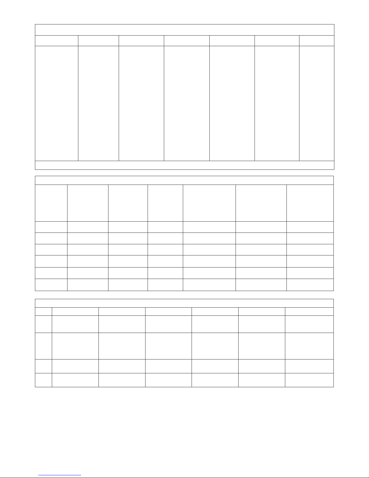
Tab.1 - Dati Generali - General Data - Allgemeine Daten - Données Générales - Datos Generales - Dane Ogólne
Dati tecnici
Technical data
Technische Daten Données technique
Datos técnicos
Dane techniczne
HYDRO
Alimentazione
Motore
Potenza assorbita
Corrente assorbita
Spinta
Pressione max
Grado di protezione
N° manovre consecutive
Pompa
Diametro stelo
Rumorosità
Protezione termica
Temp. funzionamento
Condensatore
Olio
Power supply
Motor
Absorbed power
Absorbed current
Thrust
Max pressure
Protection rating
N° cons.ve manoeuv.
Pump
Ram shaft diameter
Noise level
Overload cut-out
Operating temp.
Condenser
Oil
Versorgung
Motor
Leistungsaufnahme
Stromaufnahme
Schub
Max. Druck
Schutzart
N. Vorgänge hintereinan.
Pumpe
Schaftdurchmesser
Lärm
Thermoschutz
Betriebszeit
Kondensator
Öl
Alimentation
Moteur
Puissance absorbée
Courant absorbé
Poussée
Pression max.
Indice de protection
Nb de manœuv. conséc.
Pompe
Diamètre tige piston
Niveau sonore
Protection thermique
Temp. fonctionnement
Condensateur
Huile
Alimentación
Motor
Potencia absorbida
Corriente absorbida
Empuje
Presión máx
Grado de protección
N° maniob. consecut.
Bomba
Diámetro del vástago
Nivel de ruido
Protección térmica
Temp. de funcion.
Condensador
Aceite
Zasilanie
Silnik
Pobór mocy
Zużycie prądu
Pchnięcie
Ciśnienie max
Stopień ochrony
N° kolejnych manewrów
Pompa
średnica trzpienia
Hałaśliwość
Ochrona termiczna
Temp. działania
Kondensator
Olej
230Vac (50Hz)
1400/g/min
250 W
1,2 A
3200 N (~320Kg)
30 bar
IP55
*
a lobi
Ø 20mm
< 70 dB (a)
150°C
-20°C/+70°C
10µF
Hydro OIL
* Uso intensivo - * Intense use - * Intensive Nutzung - * Usage intensif - * Uso intensivo - * Użytkowanie intensywne
Tab.2 - Scelta del modello - Model sizing - Wahl des Modells -Choix du modèle - Elección de modelo - Wybór modelu
MODELLO
MODEL
MODELLS
MODÈLE
MODELO
MODELU
Peso max anta
Door leaf weight
Türflügelgewicht
Poids porte
Peso hoja
Ciężar skrzydła
(kg)
Lunghezza max anta
Door leaf width
Flügellänge
Longueur porte
Longitud hoja
Dł. skrzydła
(m)
Corsa utile
Stroke length
Nutzhub
Corsa utile
Carrera útil
Posuw korzystny
(mm)
Portata pompa
Pump delivery
Pumpenleistung
Débit pompe
Caudal de la bomba
Natężenie przepływu pompy
(l/min)
Velocità stelo
Ram speed
Schaftgeschwindigkeit
Vitesse tige piston
Velocidad del vástago
Prędkość trzpienia
(cm/s)
Tipologia blocco
Type of lock
Verrieglungstyp
Type de blocage
Tipología de bloqueo
Rodzaj blokady
HYDRO
300 3 270 1 1,3
¢
HYDRO BA
300 1,8 270 1 1,3
v
HYDRO BC
300 1,8 270 1 1,3
w
HYDRO
BAC
300 1,8 270 1 1,3
vw
HYDRO L
500 4 270 0,75 1
¢
HYDRO
PLUS
500 5 390 0,75 1
¢
Legenda - Legend - Legende - Légende - Leyenda - Objaśnienia
Descrizione Description Beschreibung Description Descripción Opis
¢
Reversibile
(Richiede
elettroserratura)
Reversible
(Requires
electric lock)
Reversibel
(Erfordert
Elektroverriegelung)
Réversible
(Nécessite une serrure
électrique)
Reversible
(Pedir
electrocerradura)
Odwracalny
(Wymaga
zamka elektrycznego)
v
Irreversibile in apertura
Reversibile in chiusura
(Richiede elettroserratura)
One-way opening
Reversible closing
(Requires electric lock)
Irreversibel beim Öffnen
Reversibel beim Schließen
(Erfordert
Elektroverriegelung)
Irréversible en ouverture
Réversible en fermeture
(Nécessite une serrure
électrique)
Irreversible en apertura
Reversible en el cierre
(Pedir electrocerradura)
Nieodwracalny w
otwieraniu
Odwracalny w zamykaniu
(Wymaga zamka elektrycz-
nego)
w
Reversibile in apertura
Irrevesibile in chiusura
Reversible opening
One-way closing
Reversibel beim Öffnen
Irreversibel beim Schließen
Réversible en ouverture
Irréversible en fermeture
Reversible en apertura
Irreversible en el cierre
Odwracalny w otwieraniu
Nieodwracalny w zamykaniu
vw
Irreversibile One-way Irreversibel Irréversible Irreversible
Nieodwracalny
N.B. Per ante di lunghezza superiore a 1,8m è comunque consigiabile
l'installazione dell'elettroserratuta anche nei modelli irreversibili.
Il rallentamento in chiusura è di serie su tutti i modelli.
N.B. For wings longer than 1.8m an electric lock is recommended
even on one-way models.
Slowdown in the closing stroke is standard on all models.
NB: Für Torflügel mit einer Länge von mehr als 1,8 m empfiehlt sich auch
bei irreversiblen Modellen die Installation einer Elektroverriegelung.
Die Verlangsamung beim Schließen ist bei allen Modellen serienmäßig.
N.B. En cas de vantaux d’une longueur supérieure à 1,8 m, il est
conseillé d’installer une serrure électrique également dans les
modèles irréversibles.
Le ralentissement en fermeture est de série sur tous les modèles.
N.B. En las cancelas de largo superior a 1,8 m se aconseja instalar la
electrocerradura también en los modelos irreversibles.
La deceleración en el cierre es de serie en todos los modelos.
Uwaga: Dla skrzydeł o długości powyżej 1,8m zaleca się instalowanie zamka
elektrycznego również w modelach nieodwracalnych.
Zwalnianie w zamykaniu jest seryjne we wszystkich modelach.
Page 6
6
7
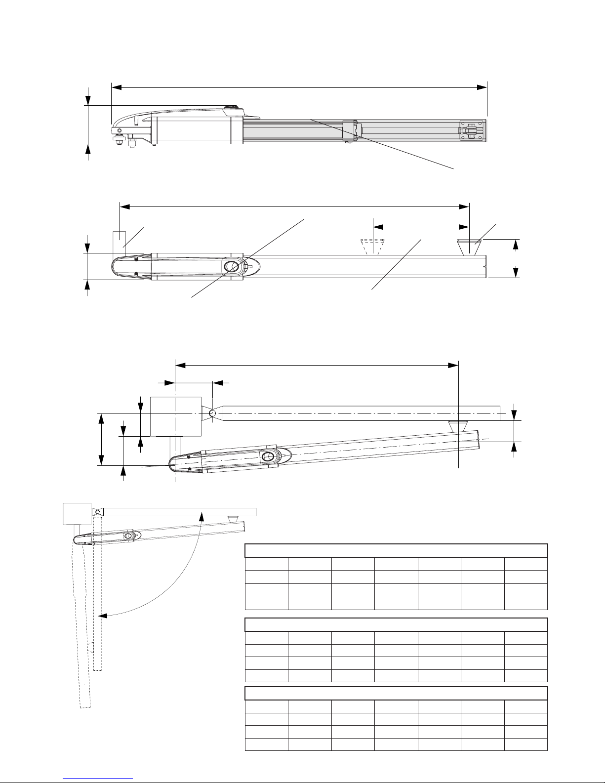
Fig.1
HYDRO PLUS
α
A (mm) B (mm) C (mm) D (mm) Z (mm) T* (s)
90° 195 195 145 50 100 40
100° 180 180 145 50 100 36
110° 130 170 120 50 100 30
B
A
C
Z
D
α
Dimensioni d’ingombro - Overall dimensions- Abmessungen
Dimensions d’encombrement- Dimensiones exteriores- Wymiary gabarytowe
Corsa.
Stroke.
Hub.
Course.
Carrera.
Posuw.
1177
(1417 Hydro Plus)
Interasse ancoraggi.
Distance between axes of anchoring bolts.
Die maximale Öffnung der Verankerungen.
Entraxe ancrages.
Distancia entre ejes ancrajes.
Współośowość elementów mocujących.
120
1098
(1338 Hydro Plus)
85
270
(390 Hydro Plus )
Mettere a livello.
Level.
Nivellieren.
Mettre de niveau.
Nivelar.
Ustawić na wysokości
P
S
Fig.2
110
(135 Hydro Plus)
HYDRO L
α
A (mm) B (mm) C (mm) D (mm) Z (mm) T* (s)
90° 135 135 85 50 75 28
100° 125 125 75 50 75 25
110° 115 115 65 50 75 23
HYDRO / HYDRO BA / HYDRO BC / HYDRO BAC
α
A (mm) B (mm) C (mm) D (mm) Z (mm) T* (s)
90° 135 135 85 50 75 22
100° 125 125 75 50 75 20
110° 115 115 65 50 75 18
*Tempo apertura indicativo, escluso rallentamento
*Indicative opening time, excluded slowdown
*Hinweisende öffnungszeit, ausschließliches Verlangsamen
*Temps indicatif d’ouverture, ralentissement exclu
*Tiempo indicativo de abiertura, deceleración excluido
*Wskazujący czas otwierania, wyłączył zwalniają
1098
(1338 Hydro Plus)
Page 7
7
V
C
D
R
P
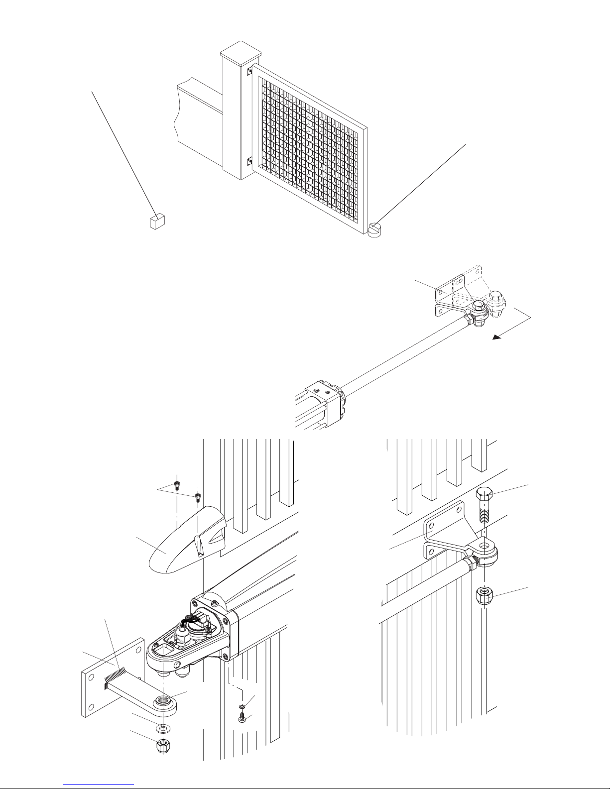
Fig.6
V
D
Avvitare o saldare.
Bolt or weld.
Einschrauben oder
schweißen.
Visser ou souder
Atornillar o soldar.
Wkręcić lub
zespawać.
Fig.5
Arresto in chiusura.
Stop when closing.
Endanschlag zur Schließung.
Arrêt en fermeture.
Tope de cierre.
Chwytak blokujący podczas zamykania.
Arresto in apertura.
Stop when opening.
Endanschlag zur Öffnung.
Arrêt en ouverture.
Tope en apertura.
Chwytak blokujący podczas otwierania.
Fig.3
Fig.4
IMPORTANTE! Estrarre completamente lo stelo e farlo rietrare di circa 10mm prima di fissare la staffa
“S” all'anta.
IMPORTANT! Slide out the ram shaft completely and then back in by approx. 10mm before fastening bracket “S” to the wing.
WICHTIG! Den Schaft ganz ausziehen und um zirka 10 mm wieder einschieben, bevor der „S“-Bügel am
Torflügel befestigt wird.
IMPORTANT! Extraire complètement la tige du piston et la faire rentrer d’environ 10 mm
avant de fixer la patte «S» au vantail.
¡IMPORTANTE! Extraer completamente el vástago y volverlo a meter unos 10 mm antes
de fijar el estribo “S” en la cancela.
WAŻNE! Wyjąć całkowicie trzpień i wpuścić go na głębokość około 10 mm jeszcze
przed zamocowaniem do skrzydła zaczepu „S”.
S
Vs
Rs
Tagliare a misura e
saldare
Cut to size and weld
Auf Maß zuschneiden und
schweißen
Couper à la bonne
mesure et souder
Cortar a medida y soldar
Wyciąć według rozmiaru
i zespawać
Grasso
Grease
Fett
Graisse
Grasa
Smar
Page 8
8
9
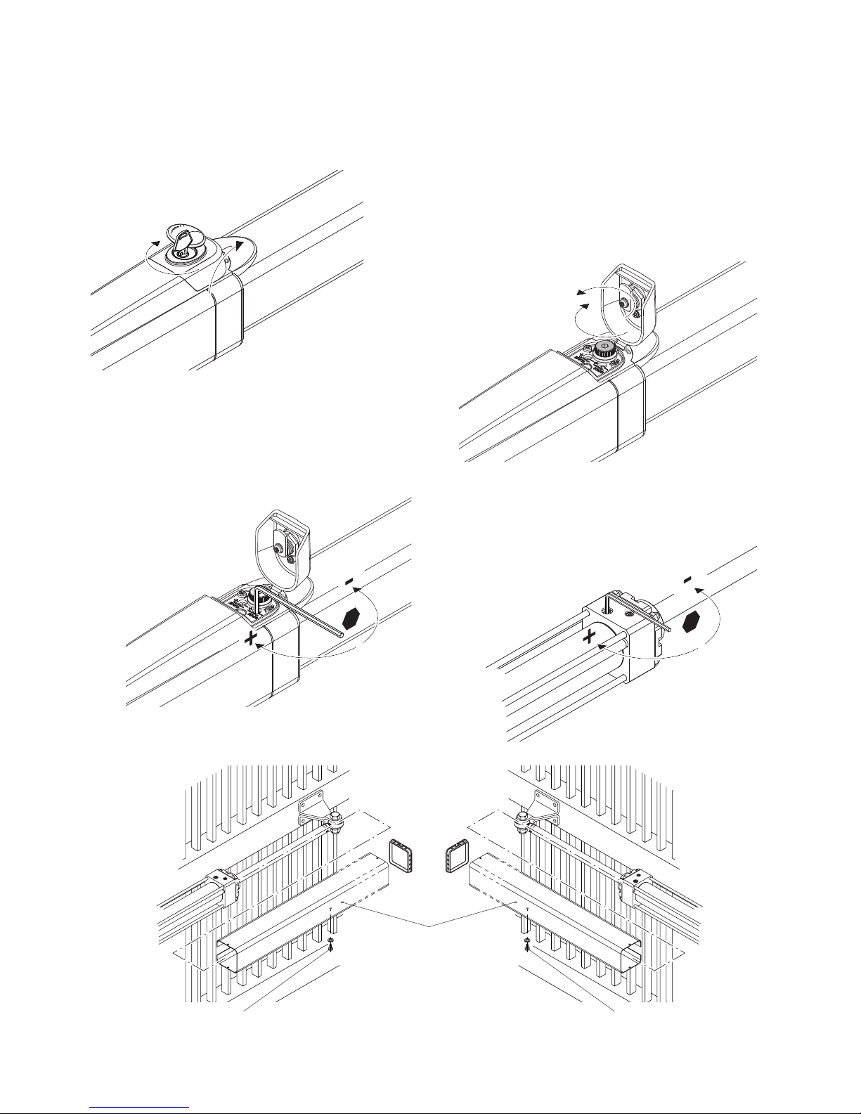
Fig.7
Aprire lo sportellino per acceddere alla manopola di sblocco
Open the protective cover to access the release knob
Die Schutzabdeckung öffnen und auf den Entriegelungsknauf zugreifen
Ouvrir le couvercle pour accéder à la poignée de déblocage
Abrir la puertecilla para acceder al pomo de desbloqueo
Otwor zyć drzwiczki by mieć dostęp do po krętła odblokowującego
Fig.11
Fig.9
Fig.10
Regolazione forza di spinta
Adjustment of the thrust
Einstellung der Schubkraft
Réglage force de poussée
Regulación de la fuerza de empuje
Regulacja siły p opychu
Regolazione rallentamento in chiusura
Adjustment of the slowdown in closing
Einstellung der Verlangsamung beim Schließen
Réglage ralentissement en fermeture
Regulación de la deceleración en el cierre
Regulacja zwalni ania w zamykaniu
1: Ruotare in senso antiorario per sbloccare l'automazione e muovere manualmente l'anta
2: Ruotare in senso orario per ripristinare il movimento automatico
1: Turn anticlockwise to disengage the operator and move the wing manually
2: Turn clockwise to engage the operator
1: Im Gegenuhrzeigersinn drehen, um die Automatisierung zu entriegeln und das Tor von
Hand zu betätigen
2: Im Uhrzeigersinn drehen, um den automatischen Antrieb wieder zu aktivieren
1: Tourner dans le sens inverse des aiguilles d’une montre pour débloquer l’automatisme
et manœuvrer manuellement le vantail
2: Tourner dans le sens des aiguilles d’une montre pour rétablir le fonctionnement
automatique
1: Girar en sentido contrario a las agujas del reloj para desbloquear la automatización y
mover la puerta en modo manual
2: Girar en el sentido de las agujas del reloj para restablecer el movimiento automático
1: Przekręcić w kierunku anty zegarowym by odblokować a utomatyzm i popychać
ręcznie skrz ydło
2: Przek ręcić w kierunku ze garowym by przywrócić działa nie automatyczne
Rimuovere la vite
To remove the screw
Die Schraube ausbauen.
Enlever la vis
Extraer el tornillo
Odkręcić śrubę
Rimuovere la vite
To remove the screw
Die Schraube ausbauen
Enlever la vis
Extraer el tornillo
Odkręcić śrubę
Fig.8
1
2
�
�
Foro di scarico sempre rivolto a terra
Drain hole faces the ground
Die Auslassöffnung muss
immer zum Boden zeigen
Trou de drainage toujours
tourné vers le sol
Orificio de descarga siempre
orientado hacia el suelo
Należy uważać na otwór spustowy
który powinien być zawsze skierowany do ziemi.
Anta sinistra
Left-hand wing
Linker Flügel
Vantail gauche
Hoja izquierda
Skrz ydło lewe
Anta destra
Right-hand wing
Rechter Flügel
Vantail droit
Hoja derecha
Skrz ydło prawe
Page 9
9
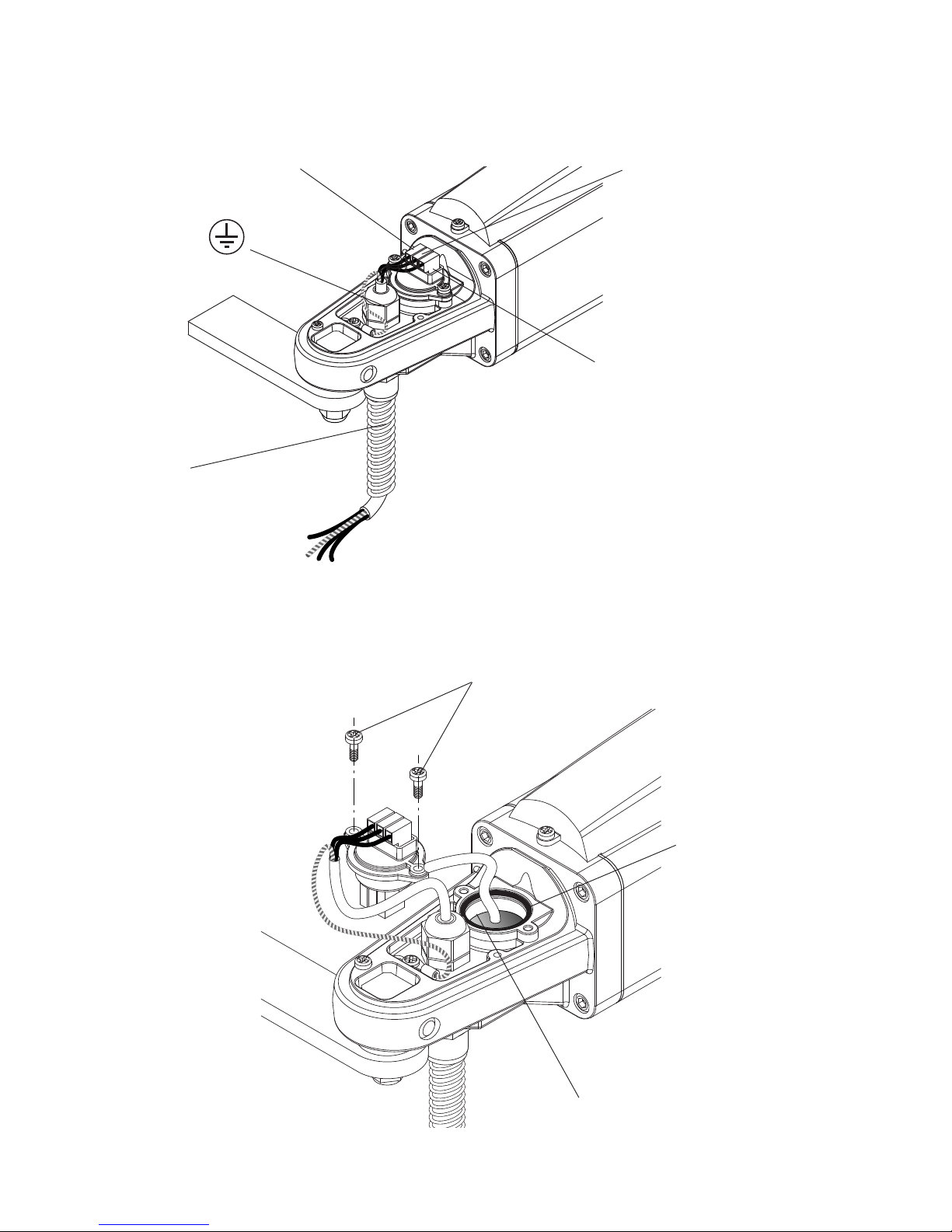
Collegamenti - Connections - Kabelanschlüsse
Connexions - Conexiones - Podłączenia
Nero= marcia motore e condensatore.
Black= motor gear and capacitor.
Schwarz= Motorgang und Kondensator.
Noir= marche moteur et condensateur.
Negro= marcha motor y condensador.
Czarny = bieg silnika i praca kondensatora
Grigio = comune.
Grey = common.
Grau = gemeinsamer Leiter.
Gris = commun.
Gris = común.
Szary = wspólny.
Marrone= marcia motore e condensatore.
Brown= motor gear and capacitor.
Braun= Motorgang und Kondensator.
Marron= marche moteur et condensateur.
Marrón= marcha motor y condensador.
Brązowy = bieg silnika i praca kondensatora
Rabbocco/sostituzione olio - Topping up/changing oil
Öl auffüllen/wechseln - Remplissage/vidange huile
Reposición/sustitución del aceite - Uzupełnianie/wymiana oleju
Il livello olio non deve superare questo spigolo
Utilizzare esclusivamente olio Hydro OIL
Never fill with oil above this rim
Only use Hydro OIL
Der Ölstand darf nicht über diese Markierung hinausgehen
Ausschließlich Öl Hydro OIL verwenden
Le niveau d’huile ne doit pas dépasser cette arête
Utiliser exclusivement de l’huile Hydro OIL
El nivel de aceite no superará este borde
Utilizar exclusivamente aceite Hydro OIL
Poziom oleju nie może pr zekraczać powyższej krawędzi
Stosować w yłącznie olej Hydro OIL
ATTENZIONE!: Prima di qualsiasi intervento togliere
alimentazione di rete
CAUTION!: Always shut-off the mains power
before working on the gate
ACHTUNG: Vor jedem Eingriff die Netzversorgung
abtrennen
ATTENTION!: Avant toute intervention couper
l’alimentation de secteur
¡ATENCIÓN!: Antes de cualquier intervención desconectar la alimentación de red
UWAGA!: Przed jakąko lwiek interwencją odłąc zyć
dopł yw prądu
Rimuovere le viti
Remove the screws
Die Schrauben ausbauen
Enlever les vis
Extraer los tornillos
Wykręcić śruby
Verificare la tenuta della guarnizione.
Check the gasket seal is tight.
Die Dichtigkeit der Dichtungen kontrollieren.
Vérifier que le joint assure l’étanchéité.
Verificar la estanqueidad de la junta.
Sprawdzić szczelność uszc zelek.
Fig.13
Fig.12
Guaina spiralata ø12
ø12 spiral sheath
Spiralmantel ø12
Gaine spiralée ø12
Vaina corrugada ø12
Osłona sp iralna ø12
Page 10
10
11
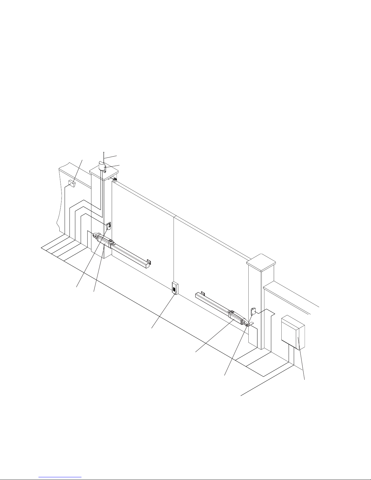
Legenda:
1 Motoriduttore Hydro
2 Fotocellule
3 Selettore a
chiave
o tastiera digitale
4 Lampeggiante
5 Antenna
6 Centrale di comando.
7 Elettroserratura
Legend:
1 Hydro geared motor
2 Photocells
3 Key selector or digital keyboard
4 Beacon
5 Antenna
6 Control unit.
7 Electric lock
Legende:
1 Hydro-Getriebemotor
2 Photozellen
3 Schlüsselwahlschalter oder Digitaltastatur
4 Blinkleuchte
5 Antenne
6 Steuerzentrale.
7 Elektroverriegelung
Légende:
1 Vérin Hydro
2 Photocellules
3 Sélecteur à clé ou clavier numérique
4 Clignotant
5 Antenne
6 Logique de commande.
7 Serrure électrique
Leyenda:
1 Motorreductor Hydro
2 Fotocélulas
3 Selector de llave o teclado digital
4 Lámpara destellante
5 Antena
6 Centralita de comando.
7 Electrocerradura
Objaśnienia:
1 Siłownik Hydro
2 Fotokomórki
3 Wybierak kluczowy lub klawiatura
przyciskowa
4 Światło migające
5 Antena
6 Stacyjka napędowa.
7 Zamek elektryczny
3
4
2
5
1
6
3x1,5 min
230Vac
2
1
2x1,5
2x1
2x1
4x1,5
4x1,5
4x1
RG 58
7
N.B.: Tenere separati i cavi di potenza da quelli ausiliari.
N.B.: The power cables must be kept separated from the auxiliary cables.
Wichtig: Leistungskabel von Hilfskabeln getrennt halten.
N.B.: Séparer les câbles de puissance des câbles auxiliaires.
N.B.: Tener separados los cables de potencia de los auxiliares.
Uwaga: należy trzymać w oddali przewody zasilania od przewodów pomocniczych.
IMPORTANTE:L'installazione dell'elettroserratura è indispensabile nei modelli sprovvisti
di blocco idraulico o comunque nelle ante di
lunghezza superiore a ml. 1,8
IMPORTANT: Installation of an electric lock is
essential on models without hydraulic lock or
if the wing is over 1.8 m long
WICHTIG: Die Installation der Elektroverriegelung ist unerlässlich bei Modellen ohne
hydraulische Verriegelung oder jedenfalls bei
Torflügeln mit einer Länge von mehr als 1,8 m.
IMPORTANT: l’installation de la serrure
électrique est indispensable dans les modèles
dépourvus de blocage hydraulique ou dans
tous les cas en présence de vantaux de plus
1,8 m de longueu
IMPORTANTE: Es imprescindible instalar la
electrocerradura en los modelos desprovistos
de bloqueo hidráulico o, de cualquier modo,
en las hojas de más de 1,8 m de largo
WAŻNE: Instalacja zamka elektrycznego jest
nieodzowna w modelach nie posiadających
blokady hydraulicznej lub w przypadku
skrzydeł o długości powyżej 1,8 m
Page 11

11
Attenzione
• Prima di procedere all’installazione leggere le istruzioni qui riportate.
• È fatto divieto assoluto di utilizzare il prodotto HYDRO per applicazioni diverse da quelle contemplate dalle
presenti istruzioni.
• Istruire l’utilizzatore all’uso dell’impianto.
• Consegnare all’utilizzatore le istruzioni ad esso rivolte.
• Tutti i prodotti CAB sono coperti da polizza assicurativa che risponde di eventuali danni a cose o persone
causati da difetti di fabbricazione, richiede però la marcatura CE della “macchina” e l’utilizzo di componenti
originali CAB.
Notizie generali
Attuatore oleodinamico per cancelli a battente, disponibile in varie versioni:
HYDRO reversibile - richiede elettroserratura
HYDRO BA blocco idraulico in apertura - richiede elettroserratura
HYDRO BC blocco idraulico in chiusura
HYDRO BAC con blocco idraulico in apertura e chiusura
HYDRO L versione lenta - richiede elettroserratura
HYDRO PLUS versione lenta con corsa maggiorata - richiede elettroserratura.
I modelli “Hydro BC” e “Hydro BAC” dotati di blocco idraulico in apertura non necessitano di elettroserratura,
garantendo il blocco meccanico dell’anta quando il motore non è in funzione.
I modelli senza blocco idraulico in apertura (Hydro - Hydro BA - Hydro L - Hydro Plus) necessitano sempre
di elettroserratura per garantire il blocco meccanico dell’anta.
Tutti i modelli sono dotati di funzione di rallentamento idraulico regolabile in fase di chiusura.
Verifiche preliminari
Per un buon funzionamento delle automazioni in oggetto, il cancello da automatizzare dovrà rispondere alle
seguenti caratteristiche:
- buona robustezza e rigidità.
- le cerniere devono presentare giochi minimi e permettere che le manovre manuali siano dolci e regolari.
- in posizione di chiusura le ante devono combaciare fra loro per tutta l’altezza.
Arresti meccanici
Nel caso non siano già presenti, è necessario predisporre degli arresti meccanici in chiusura ed apertura
(Fig.3), indipendentemente dal tipo di attuatore installato.
L'arresto meccanico in chiusura, in particolare, è indispensabile date le caratteristiche peculiari degli attuatori
oleodinamici. Vedi funzione “mantenimento blocco” nelle istruzioni della centrale di comando.
Messa in posa dell’automatismo
1 Stabilire l’altezza dal suolo dell’automatismo (si consiglia il più centrato possibile rispetto all'anta ed in
corrispondenza di un solido traverso).
Tenere presente che sul fondo dell'attuatore è presente un foro di sfiato che, in particolari condizioni, po-
trebbe aspirare dei liquidi (pioggia/neve) all'interno dell'automazione. Per questo motivo è sconsigliata una
posizione di installazione in prossimità del suolo.
2 Saldare o fissare la piastra P facendo riferimento alle quote di installazione (Fig.2) e allo schema di montaggio
(Fig.5):
- rimuovere le viti V ed il coperchio C
- inserire il perno P sulla staffa P come in figura
- fissare il tutto con la rondella R ed il dado autobloccante D
- rimuovere la vite di chiusura sfiato VS con la sua guarnizione RS. (vedi nota “Vite di sfiato”)
Rispettare le quote indicate nelle tabelle di fig. 2, modificando in caso di necessità la lunghezza della piastra.
In alcuni casi può essere necessario ricavare una nicchia nel pilastro.
Il rispetto delle quote di installazione è indispensabile per il buon funzionamento dell'attuatore.
In riferimento alle tabelle di installazione tenere presente che:
Per aperture dell'anta a 90°: A+B deve essere uguale alla corsa dell'attuatore
Per aperture dell'anta maggiori di 90°: A+B deve essere inferiore alla corsa dell'attuatore.
Mantere la differenza delle quote entro 40mm. Differenze superiori rendono irregolare il movimento dell'anta.
Al diminuire delle quote A e B aumenta la velocità dell'anta.
Page 12

12
13
Rispettare le normative vigenti.
3 Sbloccare l'attuatore (vedi paragrafo “manovra manuale)
4 Estrarre completamente lo stelo e farlo rientrare di circa 10 mm. Ribloccare l'attuatore.
E' importate lasciare una extra-corsa di sicurezza di 10 mm, sia in chiusura, sia in apertura. La corsa utile
indicata nei dati tecnici e nelle tabelle di installazione è già decurtata di questi 20 mm.
5 Mantenendo perfettamente orizzontale l'attuatore, individuare il punto di fissaggio della staffa sull'anta.
Saldare o avvitare provvisoriamente la staffa come indicato in Fig.6.
6 Sbloccare l'attuatore e verificare manualmente che l'anta sia libera di aprirsi completamente fermandosi
sugli arresti meccanici di finecorsa e che il movimento dell’anta sia regolare e privo di attriti.
7 Fissare definitivamente la staffa.
Nota: Vite di sfiato.
A fianco del foro di sfiato è presente un foro cieco dove avvitare la vite e la guarnizione per utilizzi futuri.
Appena viene rimossa la vite e durante le prime manovre dell'automazione è possibile si verifichi una piccola
fuoriuscita di olio. Ciò è normale e non comporta anomalie di funzionamento.
Manovra manuale e d’emergenza
In caso di mancanza dell’energia elettrica o di guasto, per azionare manualmente le ante procedere come
segue:
Modelli dotati di blocco idraulico (Hydro BA - Hydro BC -Hydro BAC):
• Utilizzando la chiave personalizzata, fornita in dotazione con ogni attuatore, aprire lo sportellino di protezione
del meccanismi di sblocco (Fig.7).
• Ruotare la manopola in senso antiorario per sbloccare l'automazione. (Fig.8)
• È ora possibile aprire/chiudere manualmente l'anta.
• Per ripristinare il funzionamento automatico, ruotare la manopola in senso orario.
• Richiudere a chiave lo sportellino di protezione.
Modelli sprovvisti di blocco idraulico (Hydro - Hydro L - Hydro Plus):
Questi modelli, essendo reversibili richiedono semplicemente lo sgancio dell'elettroserratura, dopodichè l'anta
può essere manovrata manualmente.
Spingere con moderazione l'anta alla sua estremità, accompagnandola per tutta la corsa. La manovra può
essere agevolata allentando la manopola di sblocco.
Regolazione forza di spinta
L'attuatore è provvisto di un dispositivo antischiacciamento (valvole by-pass) per la limitazione della forza di
spinta sull'anta in presenza di ostacolo. Una volta rimosso l'ostacolo l'anta prosegue la sua corsa per il tempo
di lavoro impostato dalla centrale di comando.
• Aprire lo sportellino di protezione, quindi utilizzando una chiave a barra esagonale da 6 mm procedere alla
regolazione della forza (Fig.9).
• Sono presenti due valvole regolabili una regola la spinta in fase di apertura (Open), l'altra regola forza in fase
di chiusura (Close).
• Rotando la valvola in direzione + si aumenta la forza di spinta dell'anta viceversa (direzione - ) la forza dimi-
nuisce.
ATTENZIONE! Questa regolazione influisce sul grado di sicurezza dell’automazione.
Verificare che la forza applicata sull’anta sia conforme con quanto previsto dalle normative vigenti.
Regolazione rallentamento in chiusura
Tutti i modelli sono provvisti di regolazione del rallentamento in fase di chiusura, per un movimento più lento
dell'anta durante gli ultimi secondi di manovra.
La regolazione del rallentamento avviene mediante l'apposita valvola (Fig.10).
Utilizzando una chiave a barra esagonale da 3mm:
- allentare (rotazione antioraria) la valvola per incrementare la velocità di rallentamento.
- fissare (rotazione oraria) la valvola per ridurre la velocità di rallentamento.
Allentando al massimo la valvola si disattiva la funzione di rallentamento.
Non forzare mai la valvola di regolazione.
Page 13

13
Posizionamento delle coperture
Una volta effettuata la regolazione del rallentamento è possibile riposizionare le coperture (Fig.11).
Prestare attenzione al foro di scarico che deve essere sempre rivolto verso terra.
Collegamenti
L'attuatore viene fornito con cavo di collegamento già inserito e collegato (Fig.12). Per il collegamento alla
centrale di comando, fare riferimento alla schema e alle istruzioni della centrale di comando.
Per proteggere il cavo di alimentazione si consiglia l'utilizzo di una guaina spiralata da 12mm da inserire
nell'apposito raccordo.
E' obbligatorio effettuare il collegamento di messa a terra.
Rabbocco/sostituzione olio
Tutti gli operatori oleodinamici richiedono una verifica periodica del livello dell'olio.
Per il rabbocco è sufficiente, dopo aver tolto alimentazione di rete all'impianto, rimuovere le due viti che fissano la morsettiera, che ha anche la funzione di tappo olio.
Il livello non deve superare lo spigolo evidenziato in Fig.13. Utilizzare esclusivamente olio Hydro OIL.
Page 14

14
15
Important
• Before installing the operator read these instructions.
• Use of a HYDRO product for any application not described in this instruction manual is prohibited.
• The user must be instructed on the use of the automation system.
• The user must be consigned the instruction manual.
• All CAB products are insured against damage or injury caused by manufacturing defects under the essential
condition that the operator has the CE marking and all genuine CAB components are installed.
General Information
Hydraulic operator for swing gates, available in various versions:
HYDRO reversible – requires an electric lock
HYDRO BA hydraulic lock on opening stroke – requires an electric lock
HYDRO BC hydraulic lock on closing stroke
HYDRO BAC hydraulic lock on opening and closing stroke
HYDRO L slow version – requires an electric lock
HYDRO PLUS slow version with extended stroke – requires an electric lock.
“Hydro BC” and “Hydro BAC” models are equipped with hydraulic lock on the opening stroke and do not require
an electric lock since the operator locks the wing shut when the motor is not in running.
Models without hydraulic lock on opening stroke (i.e. Hydro - Hydro BA.R - Hydro L - Hydro Plus) always require an
electric lock to guarantee the wing is locked shut mechanically.
All models are equipped with adjustable hydraulic slowdown on the closing stroke.
Preliminary Checks
For the gate automation to work properly, the actual gate must have the following characteristics:
- it must be robust and rigid.
- the hinges must have only limited play and provide smooth and gentle gate movements.
- the whole height of the wings must be in contact when closed.
Gate Stops
If they are not already provided, install gate stops on the opening and closing stroke limits (Fig.3) regardless of the
type of operator being installed.
The closed stop in particular is indispensable given the special characteristics of hydraulic operators. See “maintain
stop” function in the instructions for the control unit.
Installing the automation system
1 Establish the height of the automation from the ground (preferably as close to the centre of the wing as possible
and along a solid cross rail).
Remember that under the operator there is a vent hole and in certain conditions (e.g. rain or snow) it may draw
liquid into the automation. For this reason it is best not to install the operator too close to the ground.
2 Weld or otherwise anchor plate P in place, see installation distances (Fig.2) and the installation diagram (Fig.5):
- remove screws V and cover C
- insert pin P in bracket P as in the figure
- lock everything in place by washer R and self-locking nut D
- remove the vent plug VS with its gasket RS. (see note “Vent plug”)
Observe the distances given in the tables at fig. 2, correcting the length of the plate if necessary. In some cases
a recess may have to be made in the post.
It is essential that the installation distances are respected for the operator to work correctly.
With reference to the installation tables note that:
For the wing to open 90°: A+B must be equal to the operator stroke
For the wing to open more than 90°: A+B must be less than the operator stroke.
Keep the length differences within 40mm. Over this difference the wing movement becomes uneven. When reduc-
ing lengths A and B , increase the wing speed.
Comply with all statutory regulations.
3 Release the operator (see section “manual gate operation”)
4 Slide out the ram shaft completely and then slide back in by approx. 10 mm. Lock the operator in place.
Always leave a safety overrun of 10 mm in both the closing and opening strokes. The stroke length given in the
technical data and installation tables has already been reduced by the necessary 20 mm.
Page 15

15
5 Make sure the operator is kept perfectly level and mark the point where the bracket will be attached to on the
wing.
Temporarily weld or bolt the bracket in place as shown in Fig.6.
6 Release the operator and swing the gate by hand to check it moves freely to fully open and stops on the gate stop.
The wing must move smoothly and evenly.
7 Anchor the bracket permanently.
NOTE: Vent plug.
Next to the vent a dead hole has been provided where the plug and gasket can be kept for future use.
On removing the plug and during the first operator manoeuvres a small quantity of oil may leak out. This is perfectly
normal and should not be considered a fault.
Manual and emergency gate operation
If there is a power failure or malfunction the wings can be moved by hand as follows:
Models with hydraulic lock (i.e. Hydro BA - Hydro BC -Hydro BAC):
• Use the special key supplied with the operator to open the protective cover of the release mechanisms (Fig.7).
• Turn the knob anticlockwise to disengage the automation. (Fig.8)
• The wing can now be opened and closed manually.
• To engage the automation turn the knob anticlockwise.
• Lock the cover shut.
Models without hydraulic lock (i.e. Hydro - Hydro L - Hydro Plus):
Since these models are reversible, simply open the electric lock and the wing can be moved manually.
Slowly push the wing by its outer end, accompanying it all the way to the gate stop. The movement may be made
easier by slackening the release knob.
Adjusting the thrust
The operator is equipped with anti-squash by-pass valve that limit the thrust on the wing when it meets an obstacle.
Once the obstacle is removed the wing will continue its stroke for the work time set by the control unit.
• Open the protective cover and use a 6 mm hexagonal key to adjust the thrust (Fig.9).
• There are two adjustable valves, one governs the opening thrust (Open), the other governs the closing thrust
(Close).
• Turn the valve towards + to increase the thrust on the wing and vice-versa (i.e. towards - ) to reduce the thrust.
CAUTION! This adjustment is directly linked to the safety level of the automation.
Make sure that the thrust applied on the wing complies with statutory regulations.
Adjusting the closing slowdown
All models are equipped with slowdown in the closing stroke, so that the wing reduces speed during the last few
seconds of its stroke.
The slowdown is adjusted by a valve (Fig.10).
Use a 3mm hexagonal key:
- open (i.e. turn anticlockwise) the valve to increase the slowdown speed.
- close (i.e. turn clockwise) the valve to reduce the slowdown speed.
To bypass the slowdown function fully unscrew the valve.
Never force the adjustment valve.
The protective covers
After adjusting the slowdown the covers can be replaced (Fig.11).
Take great care in ensuring that the drain hole faces the ground.
Wiring
The operator is supplied with the wiring cable already installed and wired (Fig.12). To connect it to the control unit
see the diagram and instructions for the control unit.
The power cable is best protected by a 12mm spiral sheath that has to be inserted in the coupling provided.
An earth connection is compulsory.
Topping up/changing oil
The oil level in all hydraulic operators must be periodically checked.
To top up the oil first shut-off the mains power to the system and then remove the two screws on the terminal block,
which also acts as oil cap. The level must never rise above the rim shown in Fig.13. Only use Hydro OIL.
Page 16

16
17
Achtung
• Vor der Installation unbedingt diese Anleitungen lesen.
• Es ist absolut verboten, das Produkt HYDRO für andere Anwendungen einzusetzen, als die in dieser Anleitung beschriebenen.
• Den Benutzer über den Gebrauch der Anlage unterrichten.
• Dem Benutzer die für ihn bestimmten Anleitungen aushändigen.
• Alle Produkte CAB sind mit einer Versicherungspolice ausgestattet, die eventuelle Sach- oder Personenschäden abdecken, welche infolge von Fabrikationsfehlern entstehen könnten. Dies setzt jedoch die CEKennzeichnung des Geräts und die Verwendung von Originalteilen von CAB voraus.
Allgemeine Angaben
Öldynamischer Trieb für Flügeltore in verschiedenen Versionen:
HYDRO reversibel - erfordert Elektroverriegelung
HYDRO BA hydraulische Verriegelung beim Öffnen - erfordert Elektroverriegelung
HYDRO BC hydraulische Verriegelung beim Schließen
HYDRO BAC hydraulische Verriegelung beim Öffnen und Schließen
HYDRO L langsame Version - erfordert Elektroverriegelung
HYDRO PLUS langsame Version mit überdimensioniertem Hub - erfordert Elektroverriegelung.
Die Modelle „Hydro BC“ und „Hydro BAC“ mit hydraulischer Verriegelung beim Öffnen erfordern keine Elektroverriegelung, da der Flügel mechanisch verriegelt wird, wenn der Motor nicht in Betrieb ist.
Die Modelle ohne hydraulische Verriegelung beim Öffnen (Hydro - Hydro BA.R - Hydro L - Hydro Plus) erfordern
immer eine Elektroverriegelung, um die mechanische Verriegelung des Flügels zu garantieren.
Alle Modelle sind komplett mit einstellbarer hydraulischer Verlangsamung beim Schließen.
Vorbereitende Kontrollen
Für die einwandfreie Funktion der Automatisierung soll das betreffende Tor die folgenden Merkmale aufweisen:
- Es soll robust und ausreichend steif sein.
- Die Scharniere sollen Mindestspiele aufweisen und die sanfte, gleichmäßige Betätigung von Hand ermöglichen.
- In geschlossener Position sollen die Torflügel über die gesamte Höhe aufeinander passen.
Mechanische Sperren
Sofern nicht bereits vorhanden, müssen, unabhängig vom installierten Antriebstyp, mechanische Sperren für
Schließen und Öffnen vorgesehen werden (Abb. 3).
Aufgrund der besonderen Merkmale öldynamischer Triebe ist die mechanische Sperre für Schließen unbedingt
erforderlich. Siehe Funktion „Aufrechterhaltung der Sperre“ in den Anleitungen zur Steuerzentrale.
Montage der Automatisierung
1 Den Abstand der Automatisierung vom Boden bestimmen (es empfiehlt sich eine möglichst zentrale Position
im Vergleich zum Torflügel auf Höhe eines soliden Querträgers zu wählen).
Daran denken, dass sich am Boden des Triebs eine Entlüftungsöffnung befindet, durch welches unter be-
stimmten Bedingungen Flüssigkeit (Regenwasser, Schnee) in das Innere der Automatisierung eindringen
könnte. Aus diesem Grund ist von der Installation in direkter Bodennähe abzuraten.
2 Die Platte P unter Bezugnahme auf die Installationsmaße (Abb. 2) und den Montageplan (Abb. 5) anschwei-
ßen oder befestigen:
- Die Schrauben V und den Deckel C ausbauen.
- Den Bolzen P am Bügel P einstecken, wie in der Abbildung gezeigt.
- Das Ganze mit der Unterlegscheibe R und der selbstsperrenden Mutter D befestigen.
- Die Verschlussschraube der Entlüftungsöffnung VS mit der Dichtung RS ausbauen. (siehe Hinweise
„Entlüftungsschraube“)
Die in der Tabelle der Abb. 2 angegebenen Maße einhalten, wobei gegebenenfalls die Länge der Platte
anzupassen ist. In bestimmten Fällen muss vielleicht eine Nische am Pfeiler vorgesehen werden.
Die Einhaltung der Installationsmaße ist für die einwandfreie Funktion des Triebs unerlässlich.
Bezüglich der Installationstabellen ist zu bedenken:
Für Öffnungen des Torflügels von 90°: A+B muss gleich sein, wie der Hub des Triebs
Für Öffnungen des Torflügels von mehr als 90°: A+B muss kleiner sein, als der Hub des Triebs.
Page 17

17
Die Maßabweichungen dürfen nicht mehr als 40 mm betragen. Größere Unterschiede verursachen eine
unregelmäßige Bewegung des Torflügels. Bei Verringerung der Maße A und B wird die Geschwindigkeit des
Torflügels erhöht.
Die einschlägigen Normen befolgen.
3 Den Trieb entriegeln (siehe Absatz „manuelle Betätigung)
4 Den Schaft ganz ausziehen und um zirka 10 mm wieder einschieben. Den Trieb wieder verriegeln.
Es muss unbedingt ein Sicherheits-Überlauf von 10 mm an Verschluss und Öffnung vorgesehen werden.
Der unter den technischen Daten und den Installationstabellen angegebene Nutzhub ist bereits um diese
20 mm gekürzt.
5 Den Trieb perfekt waagrecht halten und den Punkt der Befestigung des Bügels am Torflügel ausmachen.
Den Bügel provisorisch anschweißen oder anschrauben, wie in der Abb. 6 gezeigt.
6 Den Trieb entriegeln und von Hand prüfen, ob sich der Torflügel ganz öffnen lässt, an den mechanischen
Endanschlägen anhält und die Bewegung des Flügels regulär und reibungslos erfolgt.
7 Jetzt den Bügel endgültig befestigen.
NB: Entlüfterschraube.
Neben der Entlüftungsöffnung befindet sich ein Blindloch, in das die Schraube und die Dichtung für zukünftige
Nutzungen eingeschraubt werden können.
Sobald die Schraube ausgeschraubt wird, und während den ersten Manövern der Automatisierung, kann unter
Umständen ein wenig Öl austreten. Dies ist durchaus normal und bedeutet keine Funktionsanomalie.
Manuelle Betätigung und Notbetrieb
Um die Torflügel im Falle eines Stromausfalls oder einer Störung von Hand zu betätigen, wie folgt vorgehen:
Modelle mit hydraulischer Verriegelung (Hydro BA - Hydro BC -Hydro BAC):
• Mit dem mit jedem Trieb mitgelieferten personalisierten Schlüssel die Schutzabdeckung der Entriegelungs-
mechanismen öffnen (Abb. 7).
• Den Knauf im Gegenuhrzeigersinn drehen, um die Automatisierung zu entriegeln. (Abb. 8)
• Jetzt kann der Torflügel von Hand geöffnet und geschlossen werden.
• Um die automatische Funktion wieder herzustellen, den Knauf im Uhrzeigersinn drehen.
• Die Schutzabdeckung mit dem Schlüssel verschließen.
Modelle ohne hydraulische Verriegelung (Hydro - Hydro L - Hydro Plus):
Da diese Modelle reversibel sind, muss lediglich die Elektroverriegelung gelöst werden, danach kann der
Torflügel manuell betätigt werden.
Vorsichtig gegen das Ende des Torflügels drücken und diesen auf dem gesamten Weg begleiten. Dieses
Manöver kann durch Lösen des Entriegelungsknaufs erleichtert werden.
Einstellung der Schubkraft
Der Trieb ist mit einem Quetschschutz (Bypass-Ventile) zur Begrenzung der Schubkraft an dem Torflügel bei
Vorliegen eines Hindernisses ausgestattet. Sobald das Hindernis beseitig ist, setzt der Torflügel seinen Weg
für die an der Steuerzentrale eingestellte Zeit fort.
• Die Schutzabdeckung öffnen und mit einem 6 mm-Sechskantschlüssel den Schub einstellen (Abb. 9).
• Es sind zwei einstellbare Ventile vorhanden, eines regelt den Schub während des Öffnens (Open), das andere
regelt die Kraft während des Schließens (Close).
• Durch Drehen des Ventils in Richtung + wird die Schubkraft des Torflügels erhöht, während umgekehrt
(Richtung - ) die Kraft verringert wird.
ACHTUNG! Diese Einstellung beeinflusst den Sicherheitsgrad der Automatisierung.
Sicherstellen, dass die am Torflügel angewandte Kraft mit den Bestimmungen der einschlägigen Normen konform ist.
Einstellung der Verlangsamung beim Schließen
Alle Modelle sind mit Einstellmöglichkeit der Verlangsamung während des Schließens ausgestattet, wodurch
eine sanftere Bewegung des Torflügels während der letzten Sekunden des Manövers erhalten wird
Die Einstellung der Verlangsamung erfolgt mit Hilfe eines speziellen Ventils (Abb. 10).
Mit einem 3 mm-Sechskantschlüssel:
- Das Ventil lockern (Drehung im Gegenuhrzeigersinn), um die Verlangsamungsgeschwindigkeit zu erhöhen.
- Das Ventil festschrauben (Drehung im Uhrzeigersinn), um die Verlangsamungsgeschwindigkeit zu verrin-
Page 18

18
19
gern.
Durch vollkommenes Aufschrauben des Ventils wird die Verlangsamungsfunktion aufgehoben.
Das Einstellventil auf keinen Fall forcieren
Anbringen der Abdeckungen
Nachdem die Verlangsamung eingestellt wurde, können die Abdeckungen wieder angebracht werden (Abb.
11).
Achtung: die Auslassöffnung muss immer zum Boden zeigen.
Anschlüsse
Der Trieb wird mit bereits eingezogenem und angeschlossenem Kabel geliefert (Abb. 12). Für den Anschluss
an die Steuerzentrale auf den Schaltplan und die Anleitungen der Steuerzentrale Bezug nehmen.
Zum Schutz des Stromkabels wird die Verwendung eines 12 mm Spiralmantels empfohlen, der an dem speziellen Anschlussstück eingesetzt wird.
Die Erdung ist obligatorisch vorgeschrieben.
Öl auffüllen/wechseln
Bei allen öldynamischen Trieben muss regelmäßig der Ölstand kontrolliert werden.
Zum Auffüllen die Anlage von der Netzversorgung trennen und die beiden Befestigungsschrauben der Klemmenleiste ausbauen, die auch als Ölstopfen dienen.
Der Stand darf die in der Abb. 13 gezeigte Markierung nicht überschreiten. Ausschließlich Öl Hydro OIL verwenden.
Page 19

19
Attention
• Avant de procéder à l’installation, lire les instructions ci-après.
• Il est absolument interdit d’utiliser le produit HYDRO pour des applications différentes de celles qui sont
décrites dans ces instructions.
• Expliquer à l’utilisateur le mode d’emploi de l’automatisme.
• Remettre à l’utilisateur les instructions qui le concernent.
• Tous les produits CAB sont couverts par une police d’assurance répondant d’éventuels dommages aux
choses ou aux personnes causés par des défauts de fabrication; cette couverture exige toutefois le marquage CE de la «machine» et l’utilisation de pièces originales CAB.
Informations générales
Vérin hydraulique pour portails battants, disponible en différentes versions:
HYDRO réversible – nécessite une serrure électrique
HYDRO BA avec blocage hydraulique en ouverture - nécessite une serrure électrique
HYDRO BC avec blocage hydraulique en fermeture
HYDRO BAC avec blocage hydraulique en ouverture et en fermeture
HYDRO L version lente - nécessite une serrure électrique
HYDRO PLUS version lente avec course majorée – nécessite une serrure électrique.
Les modèles «Hydro BC» et «Hydro BAC» avec blocage hydraulique en ouverture n’ont pas besoin de serrure
électrique pour garantir le blocage mécanique du vantail quand le moteur n’est pas en fonction.
Les modèles sans blocage hydraulique en ouverture (Hydro - Hydro BA.R - Hydro L - Hydro Plus) ont toujours
besoin de serrure électrique pour garantir le blocage mécanique du vantail.
Tous les modèles sont munis de fonction de ralentissement hydraulique réglable en phase de fermeture.
Contrôles préliminaires
Pour un bon fonctionnement des automatismes en objet, le portail à automatiser devra posséder les caractéristiques suivantes:
- robustesse et rigidité
- les charnières doivent présenter un jeu minime et permettre des manœuvres manuelles douces et régulières
- en position de fermeture, les vantaux doivent coïncider l’un avec l’autre sur toute la hauteur.
Butées mécaniques
Si elles ne sont pas présentes, il faut prévoir des butées mécaniques en fermeture et en ouverture (Fig.3),
indépendamment du type de vérin installé.
La butée mécanique en fermeture, en particulier, est indispensable vu les caractéristiques propres aux vérins
hydrauliques. Voir fonction «maintien blocage» dans les instructions de la logique de commande.
Pose de l’automatisme
1 Déterminer la hauteur de l’automatisme par rapport au sol (il est conseillé de le centrer le plus possible sur
le vantail et de le monter au niveau d’une traverse solide).
Tenir compte du fait que le fond du vérin présente un trou de drainage qui, dans certaines conditions, pour-
rait laisser pénétrer des liquides (pluie/neige) à l’intérieur de l’automatisme. C’est la raison pour laquelle il
est déconseillé d’installer l’automatisme trop près du sol.
2 Souder ou fixer la plaque P en se référant à la hauteur d’installation choisie (Fig.2) et au schéma de montage
(Fig.5):
- enlever les vis V et le couvercle C
- introduire le pivot Psur la patte P comme sur la figure
- fixer le tout avec la rondelle R et l’écrou de sûreté D
- enlever la vis de fermeture du trou de drainage VS avec son joint RS. (voir note «vis de drainage»)
Respecter les distances indiquées dans les tableaux de la fig. 2, en modifiant si nécessaire la longueur de
la platine. Dans certains cas, il peut se révéler nécessaire d’effectuer une niche dans le pilier.
Le respect des distances d’installation est indispensable pour le bon fonctionnement du vérin.
En suivant les indications des tableaux d’installation, tenir compte que:
Pour une ouverture du vantail à 90: la mesure A+B doit être égale à la course du vérin
Pour une ouverture du vantail supérieure à 90°: la mesure A+B doit être inférieure à la course du vérin.
La différence entre les deux mesures ne doit pas dépasser 40 mm. Des différences supérieures provoquent
Page 20

20
21
un mouvement irrégulier du vantail. Quand les mesures A et B diminuent, la vitesse du vantail augmente.
Respecter les normes en vigueur.
3 Débloquer le vérin (voir paragraphe «manœuvre manuelle»)
4 Extraire complètement la tige du piston et la faire rentrer d’environ 10 mm. Rebloquer le vérin.
Il est important de laisser une surcourse de sécurité de 10 mm, aussi bien en fermeture qu’en ouverture.
Dans la course utile indiquée dans les données techniques et dans les tableaux d’installation, ces 20 mm
ont déjà été déduits.
5 En maintenant le vérin parfaitement horizontal, identifier le point de fixation de la patte sur le vantail.
Souder ou visser provisoirement la patte comme l’indique la Fig.6.
6 Débloquer le vérin et vérifier manuellement que le vantail s’ouvre complètement en s’arrêtant sur les bu-
tées mécaniques de fin de course et que son mouvement est régulier et sans frottements. Fixer la patte
de manière définitive.
Note: Vis de drainage.
À côté du trou de drainage il y a un trou borgne dans lequel visser la vis et le joint pour des utilisations futures.
Quand on enlève la vis et durant les premières manœuvres de l’automatisme, il peut y avoir une petite fuite
d’huile. C’est normal et cela ne veut pas dire qu’il y a une anomalie de fonctionnement.
Manœuvre manuelle et de secours
En cas d’interruption de l’alimentation électrique ou en cas de panne, pour actionner manuellement les vantaux, procéder de la façon suivante:
Modèles avec blocage hydraulique (Hydro BA - Hydro BC -Hydro BAC):
• En utilisant la clé personnalisée, fournie avec chaque vérin, ouvrir le couvercle de protection du mécanisme
de déblocage (Fig.7).
• Tourner la poignée dans le sens inverse des aiguilles d’une montre pour débloquer l’automatisme. (Fig.8)
• Il est maintenant possible d’ouvrir/fermer manuellement le vantail.
• Pour rétablir le fonctionnement automatique, tourner la poignée dans le sens des aiguilles d’une montre.
• Refermer à clé le couvercle de protection.
Modèles sans blocage hydraulique (Hydro - Hydro L - Hydro Plus):
Ces modèles, étant réversibles demandent simplement le décrochage de la serrure électrique, ensuite le
vantail peut être manœuvré manuellement.
Pousser avec modération le vantail à son extrémité, en l’accompagnant sur toute la course. La manœuvre
peut être facilitée en desserrant la poignée de déblocage.
Réglage de la force de poussée
Le vérin est muni d’un dispositif anti-écrasement (soupape de décharge) pour la limitation de la force de poussée sur le vantail en présence d’obstacle. Une fois l’obstacle enlevé, le vantail poursuit sa course pendant le
temps de travail programmé dans la logique de commande.
• Ouvrir le couvercle de protection, puis en utilisant une clé à six pans de 6 mm, procéder au réglage de la
force (Fig.9).
• Il y a deux soupapes réglables: une règle la poussée en phase d’ouverture (Open), l’autre règle la force en
phase de fermeture (Close).
• En tournant la soupape dans le sens + on augmente la force de poussée du vantail, dans le sens contraire
(sens -) la force diminue.
ATTENTION! Ce réglage a des conséquences sur le degré de sécurité de l’automatisme.
Vérifier que la force appliquée sur le vantail est conforme à ce qui est prévu par les normes en vi-
gueur.
Réglage du ralentissement en fermeture
Tous les modèles sont munis de réglage du ralentissement en phase de fermeture, pour un mouvement plus
lent du vantail durant les dernières secondes de manœuvre.
Le réglage du ralentissement s’effectue à l’aide de la soupape spécifique (Fig.10).
En utilisant une clé à six pans de 3 mm:
- desserrer (rotation inverse horaire) la soupape pour augmenter la vitesse de ralentissement.
- fixer (rotation horaire) la soupape pour réduire la vitesse de ralentissement.
En desserrant au maximum la soupape, on désactive la fonction de ralentissement.
Page 21

21
Ne jamais forcer la soupape de réglage.
Positionnement des carters
Après avoir effectué le réglage du ralentissement, on peut remettre en place les carters (Fig.11).
Faire attention au trou de drainage qui doit toujours être tourné vers le sol.
Connexions
Le vérin est muni d’un câble de connexion déjà monté et connecté (Fig.12). Pour le raccordement à la logique
de commande, se référer au schéma et aux instructions de la logique de commande.
Pour protéger le câble d’alimentation, nous conseillons d’utiliser une gaine spiralée de 12 mm à introduire
dans le raccord prévu à cet effet.
La mise à la terre est obligatoire.
Remplissage/vidange huile
Tous les vérins hydrauliques nécessitent un contrôle périodique du niveau d’huile.
Pour le remplissage, après avoir coupé l’alimentation de secteur, il suffit d’enlever les deux vis qui fixent le
bornier qui fait aussi fonction de bouchon de l’huile.
Le niveau ne doit jamais dépasser l’arête indiquée sur la Fig.13.
Utiliser exclusivement de l’huile Hydro OIL.
Page 22

22
23
Atención
• Antes de llevar a cabo la instalación leer las instrucciones incluidas aquí.
• Está terminantemente prohibido destinar el producto HYDRO a empleos diferentes de los indicados en
estas instrucciones.
• Instruir al usuario en el uso de la instalación.
• Entregar al usuario las instrucciones a él destinadas.
• Todos los productos CAB están cubiertos con póliza de seguros que ampara los daños a cosas o a personas ocasionados por defectos de fabricación. De todas formas, soliciten el marcado CE de la ”máquina”
y el empleo de componentes originales CAB.
Noticias generales
Actuador oleodinámico para cancelas batientes disponible en varias versiones:
HYDRO reversible – pedir electrocerradura
HYDRO BA bloqueo hidráulico en apertura - pedir electrocerradura
HYDRO BC bloqueo hidráulico en el cierre
HYDRO BAC con bloqueo hidráulico en apertura y cierre
HYDRO L versión lenta - pedir electrocerradura
HYDRO PLUS versión lenta con carrera aumentada - pedir electrocerradura.
Los modelos “Hydro BC” e “Hydro BAC” dotados de bloqueo hidráulico en apertura no requieren electrocerradura, con la garantía de bloqueo mecánico de la cancela con motor inactivo.
Los modelos sin bloqueo hidráulico en apertura (Hydro - Hydro BA.R - Hydro L - Hydro Plus) requieren siempre
la electrocerradura para garantizar el bloqueo mecánico de la cancela.
Todos los modelos están provistos de función de deceleración hidráulica ajustable en la fase de cierre.
Verificaciones previas
Para el buen funcionamiento de las automatizaciones en objeto, la cancela a automatizar tendrá las características siguientes:
- buena solidez y rigidez.
- las bisagras deberán tener juegos mínimos y permitirán que las maniobras manuales sean dulces y regulables.
- en posición de cierre las puertas deberán tener contacto perfecto en toda su altura.
Topes mecánicos
En el caso no estén montados se instalarán topes mecánicos en el cierre y en la apertura (Fig.3), independientemente del tipo de actuador instalado.
En especial el tope mecánico en la fase de cierre es imprescindible, dadas las características peculiares de
los actuadotes oleodinámicos. Ver la función “mantenimiento del bloqueo” en las instrucciones de la centralita
de comando.
Puesta en marcha del automatismo
1 Establecer la altura del automatismo del suelo (se aconseja lo más centrado posible respecto de la cancela
y a la altura de una columna sólida).
Tener en cuenta que en el fondo del actuador hay un orificio de venteo que podría aspirar líquidos en con-
diciones especiales (lluvia/nieve) en el interior de la automatización. Por esta razón se desaconseja poner
la instalación cerca del suelo.
2 Soldar o fijar la placa P teniendo como referencias las cotas de instalación (Fig.2) y el esquema de montaje
(Fig.5):
- extraer los tornillos V y la tapa C
- insertar el perno P en el estribo P como en la figura
- fijar todo con la arandela R y la tuerca de autobloqueo D
- extraer el tornillo de cierre de venteo VS con su junta RS. (véase la nota “tornillo de venteo “)
Respetar las cotas indicadas en las tablas de la fig. 2, modificando el largo de la placa, de ser necesario.
En algunos casos será preciso realizar una cavidad en la columna.
El respeto de las cotas de instalación es indispensable para el buen funcionamiento del actuador.
En relación a las tablas de instalación hay que tener en cuenta que:
Para aperturas de la cancela a 90°: A+B deberá ser igual a la carrera del actuador
Para aperturas de la cancela superiores a 90°: A+B deberá ser inferior a la carrera del actuador.
Page 23

23
Mantener la diferencia de las cotas dentro de 40 mm. Si las diferencias son superiores, el movimiento de
la cancela será irregular. Al disminuir las cotas A y B aumenta la velocidad de la cancela.
Cumplir las normativas vigentes.
3 Desbloquear el actuador (véase el párrafo “maniobra manual”)
4 Extraer el vástago completamente y volverlo a meter por cerca de 10 mm. Bloquear el actuador otra vez
Es importante dejar un sobrerrecorrido de seguridad de 10 mm, tanto al cerrar como en la apertura. La
carrera útil indicada en los datos técnicos y en las tablas de instalación ya ha sido rebajada de estos 20
mm.
5 Manteniendo el actuador perfectamente horizontal, seleccionar el punto de fijación del estribo en la can-
cela.
Soldar o atornillar el estribo provisionalmente, como se indica en la Fig.6.
6 Desbloquear el actuador y comprobar manualmente que la cancela se abra completamente y que se pare
en los topes mecánicos de fin de carrera, así como que su movimiento sea regular y sin fricciones.
7 Fijar el estribo definitivamente.
Nota: Tornillo de venteo.
Al lado del orificio de venteo hay un orificio ciego donde se atornilla el tornillo y la junta para necesidades
futuras.
Al extraer el tornillo y durante las primeras maniobras de la automatización, se comprobará una pequeña
pérdida de aceite. Esto es normal y no denota anomalías de funcionamiento.
Maniobra manual y de emergencia
En caso de fallo del suministro eléctrico o de avería, para accionar las cancelas manualmente hay que hacer
lo siguiente:
Modelos dotados de bloqueo hidráulico (Hydro BA - Hydro BC -Hydro BAC):
• Empleando la llave personalizada que se entrega junto al actuador, abrir la puertecilla de protección del
mecanismo de desbloqueo (Fig.7).
• Girar el pomo en sentido contrario a las agujas del reloj para desbloquear la automatización. (Fig.8)
• Ahora se puede abrir /cerrar manualmente la cancela.
• Para restablecer el funcionamiento automático, girar el pomo en el sentido de las agujas del reloj.
• Cerrar la puertecilla de protección con la llave.
Modelos desprovistos de bloqueo hidráulico (Hydro - Hydro L - Hydro Plus):
Dado que estos modelos son reversibles, lo único que se necesita es desenganchar la electrocerradura, y
luego la cancela se puede mover manualmente.
Empujar la cancela hasta su extremidad, de forma delicada, acompañándola en toda la carrera. La maniobra
se agiliza aflojando el pomo de desbloqueo.
Regulación de la fuerza de empuje
El actuador está provisto de un dispositivo antiaplastamiento (válvulas de by-pass) para limitar la fuerza de
empuje de la cancela de haber un obstáculo. Al quitar el obstáculo, la cancela prosigue su recorrido durante
el tiempo de trabajo establecido por la centralita de comando.
• Abrir la puertecilla de protección y con el auxilio de una llave hexagonal de 6 mm, regular la fuerza (Fig.9).
• Hay dos válvulas regulables: una regula el empuje en fase de apertura (Open), y la otra regula la fuerza en
la fase de cierre (Close).
• Al girar la válvula en dirección + se aumenta la fuerza de empuje de la cancela; viceversa (dirección - ), la
fuerza disminuye.
¡ATENCIÓN! Esta regulación afecta el nivel de seguridad de la automatización.
Comprobar che la fuerza aplicada en la cancela cumpla las disposiciones de las normativas vigen-
tes.
Regulación de la deceleración en la fase de cierre
Todos los modelos están provistos de regulación de la deceleración en la fase de cierre, para obtener un
movimiento más lento de la cancela en los últimos segundos de la maniobra.
Para regular la deceleración se utiliza la válvula correspondiente (Fig.10).
Con una llave hexagonal de 3 mm:
- aflojar (rotación en sentido contrario a las agujas del reloj) la válvula para aumentar la velocidad de dece-
leración;
Page 24

24
25
- fijar (rotación en el sentido de las agujas del reloj) la válvula para disminuir la velocidad de deceleración.
Aflojando la válvula al máximo, se desactiva la función de deceleración.
No forzar nunca la válvula de regulación.
Colocación de las cubiertas
Una vez regulada la deceleración, se vuelven a colocar las cubiertas (Fig.11).
Prestar atención al orificio de descarga pues deberá estar siempre orientado hacia el suelo.
Conexiones
El actuador se suministra con el cable de conexión ya insertado y conectado (Fig.12). Para la conexión a la
centralita de comando, tener como referencia el esquema y las instrucciones de dicha centralita.
Para proteger el cable de alimentación es conveniente utilizar una vaina corrugada de 12 mm, a insertar en
el relativo racor.
Es obligatorio efectuar la conexión de puesta a tierra.
Reposición/sustitución del aceite
Todos los actuadores oleodinámicos requieren la comprobación periódica del nivel de aceite.
Para la reposición, primero desconectar la alimentación de red de la instalación y luego extraer los dos tornillos de fijación del terminal de bornes, cuya función es también de tapón de aceite.
El nivel no deberá exceder el borde indicado en la Fig.13. Utilizar exclusivamente aceite Hydro OIL.
Page 25

25
Uwaga
• Przed przystąpieniem do instalacji należy przeczytać poniższe instrukcje.
• Absolutnie zakazane jest użytkowanie produktu HYDRO do stosowań innych niż podane w niniejszych
instrukcjach.
• Udzielić użytkownikowi informacji o sposobie obsługiwania urządzenia.
• Przekazać użytkownikowi przeznaczone dla niego instrukcje.
• Wszystkie produkty CAB posiadają polisę ubezpieczeniową na pokrycie ewentualnych szkód poniesionych
przez rzeczy lub osoby wynikłych na skutek wad fabrycznych, pod warunkiem że ”maszyna” posiada
oznakowanie CE i oryginalne części CAB.
Informacje ogólne
Napęd oleodynamiczny dla bram skrzydłowych, dostępny jest w wielu wersjach:
HYDRO wersja odwracalna - wymaga zamka elektrycznego
HYDRO BA blokowanie hydrauliczne w otwieraniu - wymaga zamka elektrycznego
HYDRO BC blokowanie hydrauliczne w zamykaniu
HYDRO BAC z blokowaniem hydraulicznym w otwieraniu i zamykaniu
HYDRO L wersja wolna - wymaga zamka elektrycznego
HYDRO PLUS wersja wolna ze zwiększonym torem posuwu - wymaga zamka elektrycznego.
Modele „Hydro BC” i „Hydro BAC” będąc zaopatrzone w blokowanie hydrauliczne w otwieraniu nie
wymagają zamka elektrycznego gdyż posiadają blokowanie mechaniczne skrzydła podczas wyłączenia
się silnika.
Modele bez blokowania hydraulicznego w otwieraniu (Hydro - Hydro BA.R - Hydro L - Hydro Plus) wymagają
zawsze zamka elektrycznego by móc zapewnić blokowanie mechaniczne skrzydła.
Wszystkie modele posiadają w fazie zamykania funkcję regulacji zwalniania hydraulicznego.
Kontrola wstępna
By przedmiotowe automatyzmy mogły należycie funkcjonować, przeznaczona do zautomatyzowania
brama musi spełniać następujące wymogi:
- posiadać dobrą masywność i sztywność.
- spinacze muszą posiadać minimalny luz i pozwalać aby manewry ręczne przebiegały łagodnie i
regularnie.
- skrzydła w pozycji zamykania muszą być zbieżne względem siebie na całej wysokości.
Blokady mechaniczne
W przypadkach gdzie nie ma blokad mechanicznych, konieczne jest ich wstawienie w zamykaniu i
otwieraniu (Rys.3), niezależnie od rodzaju zainstalowanego napędu.
Szczególnie nieodzowna jest blokada mechaniczna w zamykaniu, z racji na osobliwe cechy napędów
oleodynamicznych. Zobacz funkcję „podtrzymywanie blokady” w instrukcjach do stacyjki napędowej.
Ustawianie automatyzmu
1 Ustalić dla automatyzmu wysokość od podłoża (zaleca się możliwie najbardziej ześrodkowaną względem
skrzydła i w pobliżu solidnej poprzeczki).
Należy pamiętać że na dnie siłownika znajduje się otwór wentylacyjny który, w specycznych warunkach,
mógłby wsysać ciecze (deszcz/śnieg) do wnętrza automatyzmu. Z tego to powodu przeciwskazana jest
instalacja blisko podłoża.
2 Przyspawać lub zamocować płytę P opierając się na podanych dla instalacji poziomach wysokości (Rys.2)
i na schemacie montażu (Rys.5):
- wykręcić śruby V i nakrywkę C
- wpuścić sworzeń P do zaczepu P jak pokazuje rysunek
- zamocować wszystko przez dokręcenie podkładki okrągłej R i nakrętki samoblokującej D
- wykręcić śrubę zamykającą otwór wentylacyjny VS wraz z uszczelką RS. (zobacz notę „Śruba otworu
wentylacyjnego”)
Zachować wysokości podane w tabelach na rys.2, modykując w razie konieczności tylko długość płyty.
W niektórych przypadkach może być konieczne zrobienie wnęki w podporze.
Zachowanie właściwych poziomów wysokości instalacji jest nieodzowne dla należytego
funkcjonowania napędu.
Page 26

26
27
Nawiązując do tabeli instalacyjnych należy pamiętać że:
Dla otwarcia skrzydła na 90°: A+B musi być równe do biegu napędu.
Dla otwarć skrzydła ponad 90°: A+B musi być mniejsze od biegu napędu.
Zachować różnicę wysokości w granicy 40mm. Większe różnice przysparzają nieregularności w posuwaniu
się skrzydła. Przez zmniejszenie wysokości A i B zwiększa się prędkość posuwu skrzydła.
Przestrzegać obowiązujących norm.
3 Odblokować napęd (zobacz paragraf “manewr ręczny”)
4 Wyciągnąć całkowicie trzpień wpuścić go ponownie na głębokość około 10 mm. Zablokować ponownie
napęd.
Ważne jest by pozostawić pewien zabezpieczający extra-posuw wynoszący około 10 mm, zarówno w
zamykaniu jak i w otwieraniu. Posuw korzystny podany w danych technicznych i w tabelach do instalacji
jest już zmniejszony o powyższe 20 mm.
5 Utrzymując napęd w dokładnym wypoziomowaniu, ustalić punkt dla zamocowania zaczepu do
skrzydła.
Przyspawać lub wkręcić prowizorycznie zaczep jak pokazuje Rys.6.
6 Odblokować napęd i sprawdzić ręcznie czy skrzydło posiada swobodę dla całkowitego otwarcia opierając
się o blokady mechaniczne krańcówek i czy bieg skrzydła jest regularny i nie wykazuje tarć.
7 Zamocować denitywnie zaczep.
Nota: śruba otworu wentylacyjnego.
Obok otworu wentylacyjnego znajduje się ślepy otwór do wkręcenia śruby z uszczelką dla ewentualnych
przyszłych zastosowań.
Zaraz po wykręceniu śruby i podczas pierwszych manewrów automatyzmu może się pojawić niewielki
wyciek oleju. Jest to normalne zjawisko nie wskazujące żadnych anomalii funkcjonowania.
Manewr ręczny i awaryjny
W przypadku przerwy w dopływie prądu lub usterek, by móc ręcznie popychać skrzydła należy wykonać
poniższe czynności:
Modele zaopatrzone w blokadę hydrauliczną (Hydro BA - Hydro BC -Hydro BAC):
• Stosując pilot kluczowy, dostarczony jako wyposażenie do każdego napędu, otworzyć drzwiczki
zabezpieczające mechanizmy odblokowujące (Rys.7).
• Przekręcić pokrętło w kierunku antyzegarowym by odblokować mechanizm automatyczny. (Rys.8)
• W tym momencie możliwe jest ręczne otwieranie/zamykanie skrzydła.
• By przywrócić działanie automatyczne, przekręcić pokrętło w kierunku zegrowym.
• Zamknąć kluczem drzwiczki zabezpieczające.
Modele nie posiadające blokady hydraulicznej (Hydro - Hydro L - Hydro Plus):
Modele te, jako wersja odwracalna wymagają zwyczajnego odłączenia zamka elektrycznego po czym
skrzydło może być popychane ręcznie.
Popychać z umiarem skrzydło do samego krańca przez cały tor posuwu. Manewr może być ułatwiony
przez poluzowanie pokrętła odblokowującego.
Regulacja siły popychu
Napęd wyposażony jest w mechanizm zapobiegający zgnieceniu (zawór by-pass) ograniczający siłę
popychu skrzydła w obecności przeszkody. Po usunięciu przeszkody skrzydło wykonuje swój bieg w
czasie nastawionym przez stacyjkę napędową.
• Otworzyć drzwiczki zabezpieczające, po czym używając klucza heksagonalnego o dł. 6 mm przystąpić
do regulacji siły (Rys.9).
• Występują dwa zawory regulacyjne, jeden reguluje popych w fazie otwierania (Open), drugi w fazie
zamykania (Close).
• Pokręcając zawór w kierunku + zwiększa się siłę popychu skrzydła i przeciwnie (kierunek - ) siła
maleje.
UWAGA! Powyższa regulacja ma wpływ na stopień bezpieczeństwa automatyzmu.
Sprawdzić czy nastawiona dla skrzydła siła jest zgodna z obowiązującymi normami.
Regulacja zwalniania w zamykaniu
Wszystkie modele zaopatrzone są w regulację zwalniania w fazie zamykania, zapewniającą wolniejszy
bieg skrzydła podczas ostatnich sekund posuwu.
Page 27

27
Regulacja zwalniania dokonywana jest poprzez odpowiedni zawór (Rys.10) stosując klucz heksagonalny
o dł. 3 mm.
- poluzować (pokręcanie antyzegarowe) zawór by zwiększyć szybkość zwalniania.
- zamocować (pokręcanie w kierunku zegarowym) zawór by zmniejszyć szybkość zwalniania.
Luzując zawór do maksymum wyłącza się funkcję zwalniającą.
Nie należy nigdy nadwerężać zaworu regulacyjnego.
Pozycjonowanie osłon
Po dokonaniu regulacji zwalniania możliwe jest ponowne nałożenie osłon (Rys.11).
Należy uważać na otwór spustowy który powinien być zawsze skierowany do ziemi.
Podłączenia
Napęd dostarczany posiada już przewód zasilania wprowadzony i podłączony (Rys.12). Przy podłączaniu
do stacyjki napędowej, należy opierać się na schemacie i instrukcjach do stacyjki.
Dla zabezpieczenia przewodu zasilania zaleca się stosowanie osłony spiralnej o średnicy od 12mm wzwyż
do wpuszczenia w odpowiednią złączkę.
Obowiązkowe jest podłączenie do ziemi.
Uzupełnianie/wymiana oleju
Wszystkie napędy oleodynamiczne wymagają okresowej kontroli poziomu oleju.
Dla uzupełniania wystarczające jest, po odłączeniu dopływu prądu do urządzenia, wykręcenie dwóch
śrub mocujących listwę zaciskową, która z kolei pełni funkcję zatyczki oleju.
Poziom oleju nie powinien przekraczać krawędzi widocznej na Rys.13.
Należy stosować wyłącznie olej Hydro OIL.
Page 28

28
29
17
A
19
20
22
29
23
24
26
24
27
31
F
C
D
E
34
H
G
35
8
7
15
15
1
4
5
2
6
3
B
21
10
13
14
11
12
36
28
16
18
33
30
32
9
25
Page 29

29
HYDRO
N° Denominazione - Description - Bezeichnung - Dénomination - Denominación - Określenie Cod.
1
Carter morsettiera
Terminal housing
Gehäuse
Carter bornier
Cárter terminal
Karter
CF8144101
2
OR 3118
OR 3118
OR 3118
Joint tor. 3118
OR 3118
OR 3118
CF8072418
3
Connettore
Connector
Verbinder
Connecteur
Conector
Łącznik
C5243060
4
Carter Mobile
Cover
Bew. Gehäuse
Carter mobile
Cárter móvil
Karter Ruchomy
C3747000
5
Serratura
Lock
Schloss
Serrure
Cerradura
Zamek
C3765000
6
Carter Fisso
Housing
Festes Gehäuse
Carter fixe
Cárter fijo
Karter Stały
CF8144100
7
Manopola Sblocco
Release knob
Entrieg.knauf
Poignée déblocage
Pomo desbloqueo
Pokrętło odbl.
CF8621021
8
Piastra muro
Wall plate
Wandplatte
Platine mur
Placa de muro
Płyta ścienna
CF8819032
9
Staffa posteriore
Wall bracket
Hinterer Bügel
Patte arrière
Estribo poster.
Zaczep tylny
CF8819031
10
Fondello
End plate
Bodenscheibe
Fond
Fondo
Spód
C5395001
11
Snodo
Pivot
Gelenk
Articulation
Articulación
Przegub
CF8780200
12
PG11
PG11
PG11
PG11
PG11
PG11
CF8646011
13
RPG112
RPG112
RPG112
RPG112
RPG112
RPG112
CF8516012
14
Perno snodo
Pivot lock pin
Gelenkbolzen
Pivot articul.
Perno articul.
Sworzeń przegubu
CF8621022
15
Guarnizine
Gasket
Dichtung
Garniture
Junta
Uszczelka
CF8504001
16
Serbatoio
Tank
Tank
Réservoir
Depósito
Zbiornik
C5667010
17
Motore
Motor
Motor
Moteur
Motor
Silnik
C3587050
18
Giunto
Coupling
Kupplung
Joint
Junta
Łącze
CF8424001
19
Flangia anteriore
Flange
Vord. Flansch
Bride avant
Brida anterior
Kołnierz przedni
CF8396201
20
Ghiera
Bushing
Zwinge
Bague fil.
Virola
Pierścień skurcz.
CF8426100
21
Guarnizione
Gasket
Dichtung
Garniture
Junta
Uszczelka
CF8504002
22
Stantuffo
Piston
Kolben
Piston
Émbolo
Tłok
CF8827001
23
OR 3162
OR 3162
OR 3162
Joint tor. 3162
OR 3162
OR 3162
CF8072470
24
OR 114
OR 114
OR 114
Joint tor. 114
OR 114
OR 114
CF8072100
25
Condensatore 10µF
Capacitor 10µF
Kondensator 10µF
Condensateur 10µF
Condensador 10µF
Kondensator10µF
CF8234076
26
Guarnizione
Gasket
Dichtung
Garniture
Junta
Uszczelka
CF8504060
27
Tampone
Bush sleeve
Puffer
Tampon
Tampón
Zatyczka
CF8836001
28
Testa rallentam.
Slowdown head
Kopf Verlangs.
Tête ralentiss.
Cabeza decel.
Przód zwalniania
C3396001
29
Flangia Post
Head flange
Hint. Flansch
Bride arrière
Brida post
Kołnierz Tylny
CF8396200
30
Guarnizione
Gasket
Dichtung
Garniture
Junta
Uszczelka
CF8500461
31
Rondel. 30x20x2,5
Washer 30x20x2,5
Unterl. 30x20x2,5
Rondel. 30x20x2,5
Arand. 30x20x2,5
Podkł. 30x20x2,5
CF8345030
32
Seeger D30
Snap ring D30
Seeger D30
Seeger D30
Seeger D30
Seeger D30
CF8045069
33
Raschiatore
Piston ring
Abstreifer
Segm. racleur
Rascador
Skrobak
CF8504062
34
Testa snodo
Pivot head
Gelenkkopf
Tête articul.
Cabeza articul.
Przód przegubu
CF8780010
35
Tappo
End cap
Deckel
Bouchon
Tapón
Zatyczka
CF8837150
36
Cavo alimentaz.
Power cable
Stromkabel.
Câble alim.
Cable alimen.
Przewód zasilania
CF8171160
B
Distributore per Hydro/Hydro L/Hydro PLUS - Distributor - Verteiler - Distributeur - Distribuidor - Dystrybutor
C5396003
Distributore per Hydro BA - Distributor - Verteiler - Distributeur -Distribuidor - Dystrybutor
C5396002
Distributore per Hydro BC - Distributor - Verteiler - Distributeur -Distribuidor - Dystrybutor
C5396001
Distributore per Hydro BAC - Distributor - Verteiler - Distributeur -Distribuidor - Dystrybutor
C5396000
A
Pompa per Hydro/Hydro BA/Hydro BC/Hydro BAC - Pump - Pumpe - Pompe - Bomba- Pompa (1l/min)
CF8634001
Pompa per Hydro L/Hydro PLUS - Pump - Pumpe - Pompe - Bomba- Pompa (0,75l/min)
CF8634002
C
Tubo per Hydro/Hydro BA/Hydro BC/Hydro BAC/Hydro L - Barrel - Rohrleitung - Tube - Tubo - Rura
CF8424001
Tubo per Hydro PLUS - Barrel - Rohrleitung - Tube - Tubo - Rura
CF8424002
D
Barra M6 per Hydro/Hydro BA/Hydro BC/Hydro BAC/Hydro L - M6 rod- Stange M6- Barre M6- Barra M6- Drążek M6
CF8954012
Barra M6 per Hydro PLUS - M6 rod- Stange M6 - Barre M6- Barra M6- Drążek M6
CF8954013
E
Canna per Hydro/Hydro BA/Hydro BC/Hydro BAC/Hydro L - Rod housing- Rohr - Canne- Conducto - Tuleja
CF8868002
Canna per Hydro PLUS - Rod housing- Rohr - Canne- Conducto - Tuleja
CF8868003
F
Stelo per Hydro/Hydro BA/Hydro BC/Hydro BAC/Hydro L - Ram shaft - Schaft - Tige piston- Vástago - Trzpień
CF8829001
Stelo per Hydro PLUS - Ram shaft - Schaft - Tige piston- Vástago - Trzpień
CF8868002
G
Copristelo per Hydro/Hydro BA/Hydro BC/Hydro BAC/Hydro L - Ram sleeve - Schaftdeckel - Carter piston - Cubrevástago- Osłona trzpienia
C5868000
Copristelo per Hydro PLUS - Ram sleeve - Schaftdeckel - Carter piston - Cubrevástago- Osłona trzpienia
C5868005
H
Staffa Anteriore per Hydro/Hydro BA/Hydro BC/Hydro BAC/Hydro L - Gate bracket - Vord. Bügel - Bride avant - Estribo anterior - Zaczep Przedni
CF8819030
Staffa Anteriore
per
Hydro PLUS - Gate bracket
-
Vord. Bügel
-
Bride avant
-
Estribo anterior - Zaczep Przedni
CF8819033
Page 30

30
31
Norme di sicurezza
• Non sostare nella zona di movimento delle ante.
• Non lasciare che i bambini giochino con i comandi
o in prossimità delle ante.
• In caso di anomalie di funzionamento non tentare di ri-
parare il guasto ma avvertire un tecnico specializzato.
Manovra manuale e d’emergenza
In caso di mancanza dell’energia elettrica o di guasto,
per azionare manualmente le ante procedere come
segue:
Modelli dotati di blocco idraulico
(Hydro BA - HydroBC -Hydro BAC):
• Utilizzando la chiave personalizzata, fornita in do-
tazione con ogni attuatore, aprire lo sportellino di
protezione del meccanismi di sblocco (Fig.1).
• Ruotare la manopola in senso antiorario per sbloc-
care l'automazione (Fig.2).
• È ora possibile aprire/chiudere manualmente l'an-
ta.
• Per ripristinare il funzionamento automatico, ruotare
la manopola in senso orario.
• Richiudere a chiave lo sportellino di protezione.
Modelli sprovvisti di blocco idraulico
(Hydro - Hydro L - Hydro Plus):
Questi modelli, essendo reversibili richiedono semplicemente lo sgancio dell'elettroserratura, dopodichè
l'anta può essere manovrata manualmente.
Spingere con moderazione l'anta alla sua estremità,
accompagnandola per tutta la corsa.
La manovra può essere agevolata allentando la manopola di sblocco.
Manutenzione
• Controllare periodicamente l’efficienza dello sblocco
manuale di emergenza.
• Astenersi assolutamente dal tentativo di effettuare
riparazioni, potreste incorrere in incidenti; per queste
operazioni contattare un tecnico specializzato.
• Verificare periodicamente l’efficienza dei dispositivi di
sicurezza e le altre parti dell’impianto che potrebbero
creare pericoli in seguito ad usura.
Smaltimento
Qualora il prodotto venga posto fuori servizio, è necessario seguire le disposizioni legislative in vigore al
momento per quanto riguarda lo smaltimento differenziato ed il riciclaggio dei vari componenti (metalli,
plastiche, cavi elettrici, ecc.); è consigliabile contattare il vostro installatore o una ditta specializzata ed
abilitata allo scopo.
Attenzione
Tutti i prodotti CAB sono coperti da polizza assicurativa che risponde di eventuali danni a cose o persone
causati da difetti di fabbricazione, richiede però la
marcatura CE della ”macchina” e l’utilizzo di componenti originali CAB.
Hydro
Libro istruzioni per l’utilizzatore
Fig.1
Aprire lo sportellino per acceddere alla manopola di
sblocco
1: Ruotare in senso antiorario per sbloccare l'automazione e muovere manualmente l'anta
2: Ruotare in senso orario per ripristinare il movimento
automatico
Fig.2
1
2
Page 31

31
Hydro
User’s handbook
Safety rules
• Do not stand in the movement area of the gate.
• Do not let children play with controls and near the
gate.
• Should operating faults occur, do not attempt to
repair the fault but call a qualified technician.
Manual and emergency gate
operation
If there is a power failure or malfunction the wings can
be moved by hand as follows:
Models with hydraulic lock
(i.e. Hydro BA - Hydro BC -Hydro BAC):
• Use the special key supplied with the operator to
open the protective cover of the release mechanisms
(Fig.1).
• Turn the knob anticlockwise to disengage the automation. (Fig.2)
• The wing can now be opened and closed manually.
• To engage the automation turn the knob anticlockwise.
• Lock the cover shut.
Models without hydraulic lock
(i.e. Hydro - Hydro L - Hydro Plus):
Since these models are reversible, simply open the
electric lock and the wing can be moved manually.
Slowly push the wing by its outer end, accompanying
it all the way to the gate stop. The movement may be
made easier by slackening the release knob.
Maintenance
• Every month check the good operation of the emergency manual release.
• It is mandatory not to carry out extraordinary maintenance or repairs as accidents may be caused.
These operations must be carried out by qualified
personnel only.
• Periodically check safety components and any other
parts of the system that may become hazardous if
worn.
Waste disposal
If the product must be dismantled, it must be disposed
according to regulations in force regarding the differentiated waste disposal and the recycling of components (metals, plastics, electric cables, etc..). For
this operation it is advisable to call your installer or a
specialised company.
Warning
All CAB products are covered by insurance policy for
any possible damages to objects and persons caused
by construction faults under condition that the entire
system be marked CE and only CAB parts be used.
Fig.1
Open the protective cover to access the release knob 1: Turn anticlockwise to disengage the operator and
move the wing manually
2: Turn clockwise to engage the operator
Fig.2
1
2
Page 32

32
33
Hydro
Handbuch für den Verbraucher
Sicherheitsvorschriften
• Nicht im Öffnungsbereich verweilen.
• Kinder nicht mit den Steuerungen oder in der Nähe
des Tores spielen lassen.
• Bei Funktionsausfällen nicht versuchen, den Schaden selber zu beheben, sondern den Techniker
rufen.
Manuelle Betätigung und Notbetrieb
Um die Torflügel im Falle eines Stromausfalls oder
einer Störung von Hand zu betätigen, wie folgt vorgehen:
Modelle mit hydraulischer Verriegelung
(Hydro BA - Hydro BC -Hydro BAC):
• Mit dem mit jedem Trieb mitgelieferten personalisierten Schlüssel die Schutzabdeckung der Entriegelungsmechanismen öffnen (Abb. 1).
• Den Knauf im Gegenuhrzeigersinn drehen, um die
Automatisierung zu entriegeln. (Abb. 2)
• Jetzt kann der Torflügel von Hand geöffnet und geschlossen werden.
• Um die automatische Funktion wieder herzustellen,
den Knauf im Uhrzeigersinn drehen.
• Die Schutzabdeckung mit dem Schlüssel verschließen.
Modelle ohne hydraulische Verriegelung
(Hydro - Hydro L - Hydro Plus):
Da diese Modelle reversibel sind, muss lediglich die
Elektroverriegelung gelöst werden, danach kann der
Torflügel manuell betätigt werden.
Vorsichtig gegen das Ende des Torflügels drücken und
diesen auf dem gesamten Weg begleiten.
Dieses Manöver kann durch Lösen des Entriegelungsknaufs erleichtert werden.
Wartung
• Monatliche Kontrolle der manuellen Notentriegelung
• Es ist absolut untersagt, selbstständig Sonderwartung oder Reparaturen vorzunehmen, da Unfälle die
Folge sein können; wenden Sie sich an den Techniker.
• Regelmäßig die Wirksamkeit der Sicherheitsvorrichtungen und der anderen, bei Verschleiß potentiell
gefährlichen Anlagenteile kontrollieren.
Entsorgung
Wird das Gerät außer Betrieb gesetzt, müssen die
gültigen Gesetzesvorschriften zur differenzierten
Entsorgung und Wiederverwendung der Einzelkomponenten, wie Metall, Plastik, Elektrokabel, usw., beachtet werden. Rufen Sie Ihren Installateur oder eine
Entsorgungsfirma.
Achtung
Alle Produkte CAB wurden mit einem Versicherungsschein versehen, der alle eventuellen Schäden an
Dingen oder Personen abdeckt, die durch Herstellungsdefekte hervorgerufen wurden, vorausgesetzt,
das Gerät besitzt die Kennzeichnung EU und es wurden original CAB Einzelkomponenten verwendet.
Fig.1
Die Schutzabdeckung öffnen und auf den Entriegelungsknauf zugreifen
1: Im Gegenuhrzeigersinn drehen, um die Automatisierung zu entriegeln und das Tor von Hand zu betätigen
2: Im Uhrzeigersinn drehen, um den automatischen
Antrieb wieder zu aktivieren
Fig.2
1
2
Page 33

33
Hydro
Manuel d’instructions pour l’utilisateur
Normes de sécurité
• Ne vous arrêtez jamais dans la zone de mouvement
des portes.
• Ne laissez pas les enfants jouer avec les commandes
ou à proximité des portes.
• En cas d’anomalies de fonctionnement, n’essayez
pas de réparer la panne mais contactez un technicien
spécialisé.
Manœuvre manuelle et de secours
En cas d’interruption de l’alimentation électrique ou
en cas de panne, pour actionner manuellement les
vantaux, procéder de la façon suivante:
Modèles avec blocage hydraulique
(Hydro BA - Hydro BC -Hydro BAC):
• En utilisant la clé personnalisée, fournie avec
chaque vérin, ouvrir le couvercle de protection du
mécanisme de déblocage (Fig.1).
• Tourner la poignée dans le sens inverse des aiguilles
d’une montre pour débloquer l’automatisme. (Fig.2)
• Il est maintenant possible d’ouvrir/fermer manuel-
lement le vantail.
• Pour rétablir le fonctionnement automatique,
tourner la poignée dans le sens des aiguilles d’une
montre.
• Refermer à clé le couvercle de protection.
Modèles sans blocage hydraulique
(Hydro - Hydro L - Hydro Plus):
Ces modèles, étant réversibles demandent simplement le décrochage de la serrure électrique, ensuite
le vantail peut être manœuvré manuellement.
Pousser avec modération le vantail à son extrémité,
en l’accompagnant sur toute la course. La manœuvre
peut être facilitée en desserrant la poignée de déblocage.
Maintenance
• Contrôler tous les mois le bon état du déverrouilleur
manuel d’urgence.
• S’abstenir impérativement de toute tentative d’effectuer des maintenances extraordinaires ou des
réparations, sous risque d’accident. Contactez un
technicien spécialisé pour ces opérations.
• Vérifier périodiquement l’efficacité des dispositifs
de sécurité et les autres parties de l’installation qui
pourraient représenter un risque en cas d’usure.
Démolition
Au cas où le produit serait mis hors service, il est impératif de se conformer aux lois en vigueur pour ce qui
concerne l’élimination différenciée et le recyclage des
différents composants (métaux, matières plastiques
câbles électriques, etc...) contactez votre installateur
ou une firme spécialisée autorisée à cet effet.
Attention
Tous les produits CAB sont couverts par une police
d’assurance qui répond d’éventuels préjudices corporels ou matériels provoqués à cause de défauts de
fabrication, mais qui requiert toutefois le marquage CE
de la “machine” et l’utilisation de pièces de rechange
d’origine CAB.
Fig.1
Ouvrir le couvercle pour accéder à la poignée de déblocage
1: Tourner dans le sens inverse des aiguilles d’une montre
pour débloquer l’automatisme et manœuvrer manuellement
le vantail
2: Tourner dans le sens des aiguilles d’une montre pour rétablir
le fonctionnement automatique
Fig.2
1
2
Page 34

34
35
Hydro
Libro de instrucciones para el usuario
Normas de seguridad
• No pararse en la zona de movimiento de las hojas.
• No dejar que los niños jueguen con los mando o en
proximidad de las hojas.
• En caso de anomalías de funcionamiento no intentar
reparar la avería sino que avisar a un técnico especializado.
Maniobra manual y de emergencia
En caso de fallo del suministro eléctrico o de avería,
para accionar las cancelas manualmente hay que
hacer lo siguiente:
Modelos dotados de bloqueo hidráulico
(Hydro BA - Hydro BC -Hydro BAC):
• Empleando la llave personalizada que se entrega
junto al actuador, abrir la puertecilla de protección
del mecanismo de desbloqueo (Fig.7).
• Girar el pomo en sentido contrario a las agujas del
reloj para desbloquear la automatización. (Fig.8)
• Ahora se puede abrir/cerrar manualmente la cancela.
• Para restablecer el funcionamiento automático, girar
el pomo en el sentido de las agujas del reloj.
• Cerrar la puertecilla de protección con la llave.
Modelos desprovistos de bloqueo hidráulico
(Hydro - Hydro L - Hydro Plus):
Dado que estos modelos son reversibles, lo único que
se necesita es desenganchar la electrocerradura, y
luego la cancela se puede mover manualmente.
Empujar la cancela hasta su extremidad, de forma
delicada, acompañándola en toda la carrera.
La maniobra se agiliza aflojando el pomo de desbloqueo.
Mantenimiento
• Controlar periódicamente la eficiencia del desbloqueo manual de emergencia.
• Abstenerse absolutamente de intentar efectuar
reparaciones, podrían incurrir en accidentes; para
estas operaciones contactar con un técnico especializado.
• Comprobar periódicamente la eficiencia tanto de los
dispositivos de seguridad como de las otras partes
de la instalación, que podrían crear peligros al desgastarse.
Eliminación de aguas sucias
Cada vez que el producto esté fuera de servicio, es
necesario seguir las disposiciones legislativas en vigor
en ese momento en cuanto concierne a la eliminación
de suciedad y al reciclaje de varios componentes (metales, plásticos, cables eléctricos, etc.), es aconsejable contactar con su instalador o con una empresa
especializada y habilitada para tal fin.
Atención
Todos los productos CAB están cubiertos por una
póliza de seguros que responde de eventuales daños a personas o cosas, causados por defectos de
fabricación, requiere sin embargo la marca CE de la
”máquina” y la utilización de componentes originales
CAB.
Fig.1
Abrir la puertecilla para acceder al pomo de desbloqueo
1: Girar en sentido contrario a las agujas del reloj para
desbloquear la automatización y mover la puerta en modo
manual
2: Girar en el sentido de las agujas del reloj para restablecer
el movimiento automático
Fig.2
1
2
Page 35

35
Hydro
Książeczka z instrukcjami dla użytkownika
Normy bezpieczeństwa
• Starać się nie przebywać w obszarze posuwu
skrzydeł.
• Niedopuścić aby dzieci bawiły się sterownikami lub w
pobliżu skrzydeł bramy.
• W przypadku niewłaściwego funkcjonowania nie
starać się samemu dokonywać naprawy a powiadomić
o fakcie technika wyspecjalizowanego.
Manewr ręczny i awaryjny
W przypadku przerwy w dopływie prądu lub usterek,
by móc ręcznie popychać skrzydła należy wykonać
poniższe czynności:
Modele zaopatrzone w blokadę hydrauliczną
(Hydro BA - Hydro BC -Hydro BAC):
• Stosując pilot kluczow y, dostarczony jako
wyposażenie do każdego napędu, otworzyć drzwiczki
zabezpieczające mechanizmy odblokowujące
(Rys.1).
• Przekręcić pokrętło w kierunku antyzegarowym by
odblokować mechanizm automatyczny. (Rys.2)
• W tym momencie możliwe jest ręczne otwieranie/
zamykanie skrzydła.
• By przywrócić działanie automatyczne, przekręcić
pokrętło w kierunku zegrowym.
• Zamknąć kluczem drzwiczki zabezpieczające.
Modele nie posiadające blokady hydraulicznej
(Hydro - Hydro L - Hydro Plus):
Modele te, jako wersja odwracalna wymagają
zwyczajnego odłączenia zamka elektrycznego po czym
skrzydło może być popychane ręcznie.
Popychać z umiarem skrzydło do samego krańca przez
cały tor posuwu. Manewr może być ułatwiony przez
poluzowanie pokrętła odblokowującego.
Konserwacja
• Sprawdzać okresowo sprawność działania ręcznego
mechanizmu odblokowującego i bezpieczeństwa.
• Nie starać się w żadnym wypadku dokonywać napraw
samemu z racji na możliwość ulegnięcia wypadkowi,
w celu naprawy należy skontaktować się z technikiem
wyspecjalizowanym.
• Sprawdzać okresowo sprawność przyrządów
zabezpieczających i innych części urządzenia
mogących stanowić zagrożenie na skutek ich
zużycia.
Eliminacja i demolowanie
W przypadku gdy urządzenie nie nadaje się już do
dalszego użytkowania, w celu pozbycia się go należy
ściśle przestrzegać obowiązujących w danym momencie
norm prawnych regulujących zróżnicowany rozkład na
części i odzyskiwanie niektórych elementów składowych
(metale, plastyk, kable elektryczne, itp.); wskazane jest
skontaktowanie się z instalatorem lub wyspecjalizowaną
rmą, autoryzowaną do tego rodzaju prac.
Uwaga
Wszystkie produkty CAB objęte są polisą
ubezpieczeniową na pokrycie szkód poniesionych
przez rzeczy lub osoby w wyniku wad produkcyjnych,
pod warunkiem że urządzenia posiadają oznakowanie
CE i oryginalne części CAB.
Fig.1
Otworzyć drzwiczki by mieć dostęp do pokrętła
odblokowującego
1: Pr zekręcić w kierunku antyze garowym by
odblokować au tom aty zm i popychać ręcznie
skrzydło
2: Przekręcić w kierunku zegarowym by przywrócić
działanie automatyczne
Fig.2
1
2
Page 36

CL8542500 Rev.07/05/00
 Loading...