

Page 1
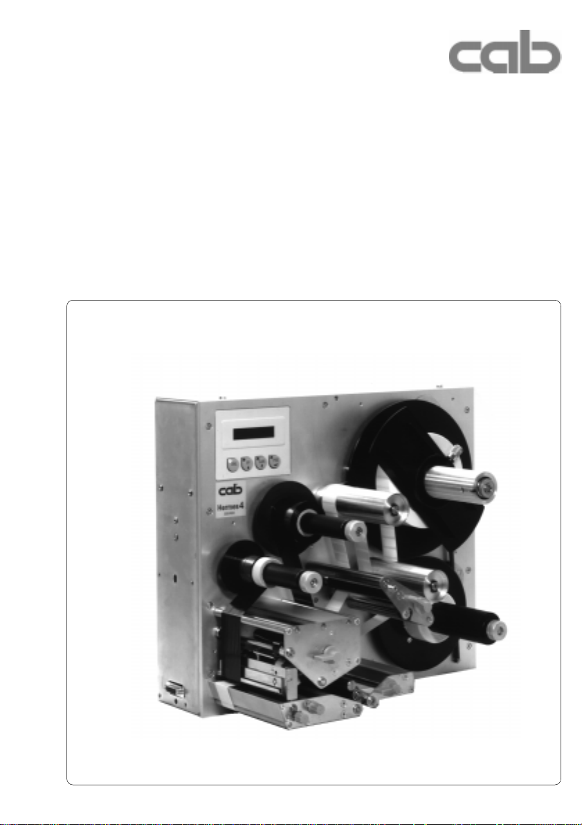
Transfer Printer
Hermes
Hermes 4N / Hermes 5N
Hermes 4F / Hermes 5F
Technical Information
Edition 8/00
Page 2

cab-Produkttechnik
Gesellschaft für
Computer- und AutomationsBausteine mbH & Co.KG
Postfach 19 04 D-76007 Karlsruhe
Wilhelm-Schickard-Str. 14 D-76131 Karlsruhe
T elefon 0721 / 66 26-00
T elefax 0721 / 66 26-249
copyright by cab / 900 8127 / K34 / 1
T echnische Änderungen vorbehalten
In accordance with our policy of continual product improvement, we reserve the right to alter specifications without notice
Données technique modifiables sans prévais
2 cab - Produkttechnik GmbH
Page 3
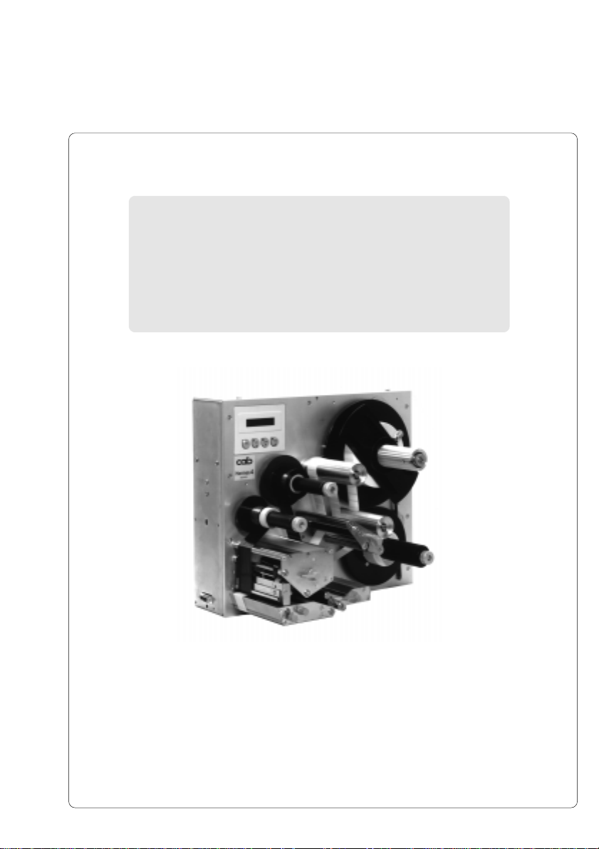
Hermes
Thermal Transfer Printer
Thermal Transfer Printer
Technical Information
Technical Information
All rights reserved, including those of the translations.
No part of this manual nor any translation may be reproduced or transmitted in any
form or by any means, for any purpose other than the purchaser's personal use,
without the express written permission of cab - Produkttechnik GmbH Karlsruhe.
Edition 8/00
Printed in Germany
3cab - Produkttechnik GmbH
Page 4

Table of Contents
A General Guide to the Documentation............................................................................... 6
Compliances ........................................................................................................................... 7
Trademarks ............................................................................................................................. 7
Characteristics of the Thermal Printhead ........................................................................... 8
1. Product Description ........................................................................................................ 9
General Information........................................................................................................... 9
Important Information about Printing with Hermes ........................................................... 9
Overview of the Hermes Types ....................................................................................... 10
Overview of the Optional Features.................................................................................. 10
Technical Specifications .................................................................................................. 11
Optional Features ............................................................................................................ 14
Warning Sensor Label End / Ribbon End................................................................. 14
Warning Light ............................................................................................................ 14
Memory Card............................................................................................................. 14
Keyboard Adapter ..................................................................................................... 14
Label Design Software EASYLABEL for Windows .................................................. 14
Print Media.......................................................................................................................15
Print Media for Direct Thermal Printing .................................................................... 16
Print Media for Thermal Transfer Printing ................................................................ 16
Label/ Tag Media Specifications ............................................................................... 17
Transfer Ribbon......................................................................................................... 18
2. General Safety Instructions .......................................................................................... 19
3. Delivery Contents .......................................................................................................... 19
4. Printer Component Location ........................................................................................ 20
5. Connecting the Printer.................................................................................................. 28
Connection to Power Supply ........................................................................................... 28
Connection to a Computer .............................................................................................. 29
Switch on the Printer ....................................................................................................... 30
6. Media Loading ............................................................................................................... 31
Preparation of the Label Supply Hub .............................................................................. 31
Loading Labels ................................................................................................................ 32
Loading Transfer Ribbon ................................................................................................. 34
7. Adjustments Concerning the Labels ........................................................................... 35
Adjustment of the Label Edge Sensor ............................................................................ 35
Adjustment of the Printhead Support .............................................................................. 36
Adjustment of the Label Tracking .................................................................................... 37
Adjustment of the Transfer Ribbon ................................................................................. 38
4 cab - Produkttechnik GmbH
Page 5

8. Options ........................................................................................................................... 39
Applicators ....................................................................................................................... 39
Non-cab-Applicators.................................................................................................. 39
cab-Applicators ......................................................................................................... 40
Bracket............................................................................................................................. 42
Feet .................................................................................................................................. 44
Warning Light ...................................................................................................................45
Warning Sensors ............................................................................................................. 46
Warning Sensor Label End ....................................................................................... 46
Warning Sensor Ribbon End .................................................................................... 48
9. Control Panel .................................................................................................................51
System Mode ONLINE .................................................................................................... 52
System Mode OFFLINE .................................................................................................. 52
System Mode PRINT....................................................................................................... 52
System Mode PAUSE...................................................................................................... 53
System Mode LABEL FROM CARD ............................................................................... 53
10. Setup ............................................................................................................................... 54
11. Error Messages .............................................................................................................. 56
Correctable Errors ........................................................................................................... 56
Irrecoverable Errors ......................................................................................................... 56
Appendices
Appendix A - Built-in Dimensions .................................................................................... A-1
Hermes 4N..................................................................................................................... A-2
Hermes 4F ..................................................................................................................... A-3
Hermes 5N..................................................................................................................... A-4
Hermes 5F ..................................................................................................................... A-5
Appendix B - Pin Assignment of the Interface Connectors .......................................... B-1
Pin Assignment of the Serial Interface Connector........................................................ B-1
Interface Cable for RS-232............................................................................................ B-2
Interface Cable for RS-422 / RS-485 ............................................................................ B-3
Pin Assignment of the Parallel Interface Connector ..................................................... B-4
Centronics Interface Cable ............................................................................................ B-4
Pin Assignment of the Peripheral Port for Non-cab-Applicators .................................. B-5
Appendix C - Spare Parts List (Extract)........................................................................... C-1
EC-Conformity Declaration
5cab - Produkttechnik GmbH
Page 6

A General Guide to the Documentation
T echnical Information
The present manual contains beside the Technical Specification and the most
important instructions for the operator especially information for the integrators
of Hermes printers. This covers the built-in dimensions, the description of the
different interfaces and the pin assignments of the interface cables.
Note the directions for use on recommended material and the properties of the
thermal printhead in order to avoid damage and premature failure of your
Hermes .
Every effort has been made in the creation of this manual to provide as much
information as possible in an understandable manner.
We welcome your comments and suggestions regarding additions or
corrections to improve future editions of this manual. Please, let us know if you
have any questions.
Further Documentation
Complete information on the use of the Hermes printers are included in the
Operator's Manual.
The programming of the Hermes printers is completely compatible to the
programming of cab's Apollo. Therefore it is possible to use the information,
that can be found in the "Programming Instructions - Apollo".
Detailed information about service and maintenance are included in the
"Service Manual" of the Hermes. (e.g. replacement of components, adjustment
instructions, circuit diagrams, spare parts lists, etc.)
6 cab - Produkttechnik GmbH
Page 7

Compliances
Hermes complies with the following safety regulations :
CE : Hermes complies with the following safety requirements:
FCC : Hermes complies with the requirements of the FCC regulations part 15 for
- EC Low Voltage Directive (73/23/EEC)
- EC Machinery Directive (89/392/EEC)
- EC Electromagnetic Compatibility Directive
(89/336/EEC/ foll. 93/31/EEC)
class A computers. Under disadvantageous circumstances, the operation of
these devices may cause interference with radio or TV reception, which has to
be eliminated by the operator.
Trademarks
Centronics
Corporation.
MacintoshMicrosoft
Bitstream
Speedo
TrueType
Easylabel
® is a registered trademark of Microsoft Corporation.
® is a registered trademark of Bitstream, Inc.
™ is a registered trademark of Bitstream, Inc.
™ is a registered trademark of Apple Computer, Inc.
® is a registered trademark of Centronics Data Computer
Computer is a product of Apple Computer, Inc.
® is a registered trademark of Tharo Systems, Inc.
7cab - Produkttechnik GmbH
Page 8

Characteristics of the Thermal Printhead
CAUTION !
The thermal printhead is the most sensitive part of your printer.
Pay special attention to the following guidelines :
1) The glass cover on the printhead must not be touched with the hand.
Do not use any sharp items, such as knives or screwdrivers, to clean
the printhead.
2) During printing, always take care that there is no dirt or foreign
objects on the labels in order to avoid impurification of the printhead.
This way, the printhead might be damaged.
3) Use proper label material with a smooth surface only.
A rough surface will affect the printhead and may cause damage and
reduce its operating life.
4) Clean the printhead regularly with a special printhead cleaning pen, or
an isopropyl alcohol soaked cotton swab.
5) Print with the lowest possible printhead temperature.
Careful use will allow you to print approximately between 18 to 30 miles
(30 to 50 km) of print media before the printhead needs replacing.
Improper usage can cause damage to the printhead.
8 cab - Produkttechnik GmbH
Page 9

1 Product Description
General Information
The Thermal Transfer Printers of the Hermes family are especially developed
for fully automatic labelling. Therefore the print mechanism is totaly aligned to
dispense labels. The printhead is arranged low within the devices to minimize
the way of the labels from the peel-off position to labelling position on the
product and to increase the labelling rate.
After removing the dispensed label the label strip can be fed back. So the
printing of the next label may start at the front label edge.
Hermes has two separate label transport systems for forward and backward
feed. These systems guarantee a high precision in printing and applying labels
independent from the size of the label supply roll.
The Hermes is an innovative label printer which may be used in either direct
thermal or thermal transfer mode. The programming of the Hermes is
completely compatible to the Apollo printers.
With the high-class printheads (305 dpi near edge printhead at Hermes 4N/5N
or 300 dpi flat printhead at Hermes 4F/5F) it is possible to print bar codes and
graphics quick, brilliant and tidy .
The double lined LCD display keeps the operator constantly informed about the
current status of the printer. The setup menu allows easy configuration
changes whenever desired.
The options PCMCIA-memory-card and keyboard adapter, which are offered in
the Apollo-program, may also be used for Hermes.
Important Information about Printing with Hermes
The print mode of the Hermes is designed for fully automatic labelling.
Therefore after the start of a print job Hermes needs two additional signals for
the processing of every single label :
- a start signal that releases printing and dispensing of the label
- a signal that shows the removing of the label from the peel position.
NOTICE !
If you operate Hermes with a non-cab-applicator make sure that the
applicator or the control system can generate these two signal.
A simple print mode without the "start" and the "removed" signals is not
available.
All cab applicators provide the needed signals.
9cab - Produkttechnik GmbH
Page 10
Overview of the Hermes T ypes
The present documentation contains the description of four different Hermes
types :
Part.-No. Description
5537500 Hermes 4N
5537501 Hermes 5N
5537503 Hermes 4F
5537506 Hermes 5F
The most important differences between Hermes types are :
- the type of the printhead
Hermes 4N/5N : Near edge printhead with 305 dpi
Hermes 4F/5F : Flat printhead with 300 dpi
- the maximum diameter of the label supply roll
Hermes 4N/4F : 7.9" / 200 mm
Hermes 5N/5F : 11.8" / 300 mm
Further the devices only will be called as Hermes, where are no differences
between the types.
Overwiew of the Optional Features
For the devices of the Hermes familiy the following optional features are
available.
Part.-No. Description
5537742 Warning Sensor Label End Hermes 4
5537743 Warning Sensor Ribbon End Hermes 4
5537744 Warning Sensor Label End Hermes 5
5537745 Warning Sensor Ribbon End Hermes 5
5537747 Warning Light
5537748 Feet Hermes 4/5
5942471 Bracket Hermes 4
5942472 Bracket Hermes 5
5533900 PC Keyboard Adapter
5560406 PC Card, 2 MB
5560405 PC Card, 4 MB
10 cab - Produkttechnik GmbH
Page 11

T echnical Specifications
Type : Direct thermal/ Thermal transfer printer
Printhead : Hermes 4N/5N : Thin film transfer printhead in near edge technology
Resolution: Hermes 4N/5N : 305 dpi = 12 dots / mm
Number of dots/ line : 1280
Print width : Hermes 4N/5N : 4.2 in (106.6 mm)
Print speed : Hermes 4N/5N : 4, 5, 6, 7, 8 ips (100, 125, 150, 175, 200 mm/s)
Available fonts : 5 Bitmap fonts incl. OCR-A and OCR-B
Character sets : Windows 1252/1250, IBM Codepage 850/852,
Character size : For scaleable fonts : width and height .035 to 5 in ( 0,9 - 128mm)
Font style : bold, italic, underlined, mirror-inverted, outlined, revers, grey
Font rotation : Bitmap fonts/Bar codes : 0°, 90°, 180°, 270°
Graphic elements : Line, box, circle, ellipse, fill-in segment, arrow
Graphic file type: .PCX, .IMG, .BMP, .TIF, .GIF und .MAC files
Bar codes : Lineal codes for industry, logistics, medicine :
Hermes 4F/5F : Thin film transfer printhead in flat head technology
Hermes 4F/5F : 300 dpi = 11.8 dots / mm
Hermes 4F/5F : 4.3 in (108 mm)
Hermes 4F/5F : 2.6, 4, 5.2, 6.5, 8 ips (66, 100, 133, 166, 200 mm/s)
3 scaleable fonts (Speedo™) - internally
Speedo™ and TrueType™fonts - to load externally
ISO 8859-1, ISO 8859-8, EBCDIC, Macintosh,
Supports all Western and Eastern European Latin characters
are individually changeable
For Bitmap fonts : width and height .04 to .12 in (1 - 3 mm )
the size is selectable up to a factor of 10
Scaleable fonts : optional, texts in circular format
Code 39, Code 93, Code 128 A,B,C, Codabar,FIM, HIBC,
Interleaved 2/5, Ident-/Leitcode der Deutschen Post AG,
MSI, Plessey, Postnet,
Lineal codes for the trade :
EAN-8, EAN-13, EAN-128, EAN/UCC 128, EAN/UPC
App 2, EAN/UPC App 5, JAN-8, JAN-13, UPC-A, UPC-E
Area codes :
Data Matrix, PDF417, UPS-Maxicode
Bar code height, modul with, and ratio are variable, with/without
check digit, human readable character, start/stop character
11cab - Produkttechnik GmbH
Page 12

Processor : 32 Bit, Motorola
Memory : Internal memory 2 MB
PCMCIA connector : for PC Card 512 KByte, 2 MByte, 4 MByte
Interface : Serial : RS-232, RS-422, RS-485 1200-57600 Baud
Peripheral ports : - Interface for the connection of non-cab-applicators and
Ribbon saver : The printhead only will be pressed against the print roller if the printer
Backfeed : In order to start the print of a label always from the front edge the
Test features : System test when switching on
Label material : Thermal paper, normal paper, plastic foil,
Internal rewinder : To rewind the backing paper
Parallel : Centronics
for the signals of the warning sensors label/ribbon end
- SPI-Interface for the connection of cab-applicators
has to print information. At the other time the printhead will be lifted
and the transport of the transfer ribbon will be stopped.
label strip may fed back after the completion of the previous label
print.
To avoid an abrasion of the transfer ribbon at the label the printhead
wil be lifted during the backward transport.
Self test with printout of firmware data and system parameters
PE, PP, PVC, Polyamide
Adhesive labels : 60-160 g/sqm
Material width : 4.7 in (120 mm)
Label width : .4-to 4.5 in (10-116 mm)
Label length : .2 to 21.5 in (5-546 mm)
Core diameter : 3 in (76 mm)
Supply roll diameter : Hermes 4N/4F : up to 7.9 in (200 mm)
Hermes 5N/5F : up to 11.8 in (300 mm)
Labels may be wound face-in or face-out on the supply roll
Core diameter : 1.6" (40 mm)
Max. rewinding diameter : Hermes 4N/4F : 5.7 in (145 mm)
Hermes 5N/5F : 8.3 in (210 mm)
Material recognition : - Gap sensor ("see through")
- Bottom reflective sensor
- Top reflective
adjustable from .08 to 1.85 in (2 to 47 mm)
12 cab - Produkttechnik GmbH
Page 13

Transfer ribbon : Type : Hermes 4N/5N : preferably ribbons designed for the
Hermes 4F/5F : standard ribbons
Length : 1476' in (450 m)
Width : max. 4.3 in (110 mm)
Core diameter : 1 in (25 mm)
Max. roll diameter : 3.6 in (92 mm)
Colour : inside or outside
Control panel : 4 Function keys with LED display
Backlit LCD with 2 lines of text, 16 characters per line
LCD can be set to display in 8 different languages
Control features : Print stop and error message at the LCD display at
- Paper out
- Ribbon out
- Printhead/ Transport system open
Information via peripheral interface and warning light at
- passing the adjusted minimum diameter of the supply roll of
labels or transfer ribbon (if the warning sensors are installed)
Dimensions : Hermes 4N/4F : Heigth : 15.4 in (390 mm), Width : 10.9 in (277 mm),
Hermes 5N/5F : Heigth : 21.3 in (542 mm), Width : 10.9 in (277 mm),
Weight : Hermes 4N/4F : 46.3 lb. (21 kg)
Hermes 5N/5F : 55.2 lb. (25 kg)
Operating voltage : Switcheable between 230 V A.C/ 50 Hz or 115 V A.C/ 60 Hz
Maximum 1,5 A (at 230 V) / 3 A (at 115 V)
power input :
Circuit protection : T 4 A (at 230 V) / T 6.3 A (at 115 V)
Environment : Operation at 50° to 95°F (10° to 35°C) at a humidity of 30 to 85%
Transport at -13° to 158°F (-25° to +70°C) at a max. humidity of 95%
Storage at 41° to 104°F (5° to 40°C) at a humidity of 5 bis 85%
use with near edge printheads
1968' in (600 m) on inquiry
Depth :16.5 in (420 mm)
Depth : 21.3 in (542 mm)
non-condensing
13cab - Produkttechnik GmbH
Page 14

Optional Features
Warning Sensor Label End / Transfer Ribbon End
These sensors signalize, when the diameter of the label supply roll respectively
the transfer ribbon roll has decreased below a preset thresould value. The
messages will be shown by switching on the yellow lamp of the warning light
(option). The signals also can be sent to a control system by using the
peripheral interface. So the user has the possibility to optimize the moment for
loading new media by regarding the whole process.
Warning Light
By using the warning light it is possible to recognize the state of the printer with
one view. The different colors of the lamps show the several possibilities,
whether the printer is switched on, there is an printer error or the preset
minimum quantity of labels or transfer ribbon is passed.
PC Memory Card
Hermes includes an option for using memory cards in order to permanently
store graphics, fonts, databases or whole label formats.
The data can be downloaded via interface.
PCMCIA 2.1 conforming sRAM cards or Flash-EPROM cards are accepted.
The maximum capacity is 4 MegaByte.
Using a memory card, the printer can be operated without being connected to
a computer which represents a great advantage regarding the flexibility.
Keyboard Adapter
The keyboard adapter allows you to connect your Hermes to a MF-2
compatible PC keyboard using the serial interface. This will allow you to modify
variable data stored on a memory card.
Label Design Software EASYLABEL for Windows
EASYLABEL is an intelligent and useful label design software which is easy to
use in connection with your Hermes.
EASYLABEL can be run on all Microsoft Windows compatible computers.
For further information about EASYLABEL, contact your local reseller.
14 cab - Produkttechnik GmbH
Page 15

Print Media
Hermes can be operated in direct thermal as well as thermal transfer mode.
For direct thermal mode, only use print material with a thermal-reactive coating.
The print image is transferred by heating the material at the printhead, causing
a reaction on the surface of the paper and, consequently, darkening the
material.
In thermal transfer mode, not only standard paper labels are needed but also
the thermal transfer ribbon with a color surface. The printout is created by
heating the transfer ribbon, causing a transfer of color particles onto the label.
Hermes allows to regulate the heat level and also the print speed. Thus, the
Hermes offers a wide range of opportunities for usage.
Hermes 4N and Hermes 4F are able to print on labels with a maximum supply
roll diameter of 8 in (200 mm) and a core diameter of 3 in (76 mm). Hermes 5N
and Hermes 5F can use labels with a maximum supply roll diameter of 12 in
(300 mm) and a core diameter of 3 in (76 mm).
The ability of label edge recognition, which guarantees the precise position of
the printer output, is accomplished by a moveable photocell. This sensor is
controlled by the processor of the Hermes and ensures recognition for different
sorts of material. There is no need for additional electronic adjustment.
On the following pages, you will find detailed information and specifications
concerning suitable materials.
If in doubt, we will perform test prints with your label material to find the best
suitable transfer ribbon.
15cab - Produkttechnik GmbH
Page 16

Print Media for Direct Thermal Printing
The print material must correspond to several important specifications, in order
to ensure high quality printing, and to avoid damage to the printhead or early
wear.
Using labels which we have tested and which we recommend to our
customers, will guarantee a gentle treatment of the printhead. If you want to
use material by another supplier, please note the following requirements
regarding the condition of thermal printer paper :
1. To avoid damage to the printhead, the surface coating must cover the
thermal-reactive layer. If the coating is too thin, this may cause a 'pitting'
effect on the printhead, i.e. very small explosions during the chemical
reaction of the thermal coating quickly resulting in damage to the printhead.
2. The surface of the labels should be very smooth to avoid a 'sandpaper'
effect on the printhead.
3. Always choose material which can be printed on with the lowest possible
heat level. The greater the heat level, the shorter the life of the printhead.
Moreover, with highest heat levels the phases of heating up and cooling
down extend. This may have a negative effect on the print quality,
especially if a high print speed is required.
Print Media for Thermal Transfer Printing
In thermal transfer mode, a wide range of different label materials may be
used. (e.g. normal paper, tag stock, a variety of synthetic material such as
polyester foil, etc.)
NOTICE !
The print quality greatly depends on the right combination of label
material and transfer ribbon.
The surface of the labels determines which ribbon material may be used.
Unsuitable ribbons may cause an extremely poor print image.
16 cab - Produkttechnik GmbH
Page 17
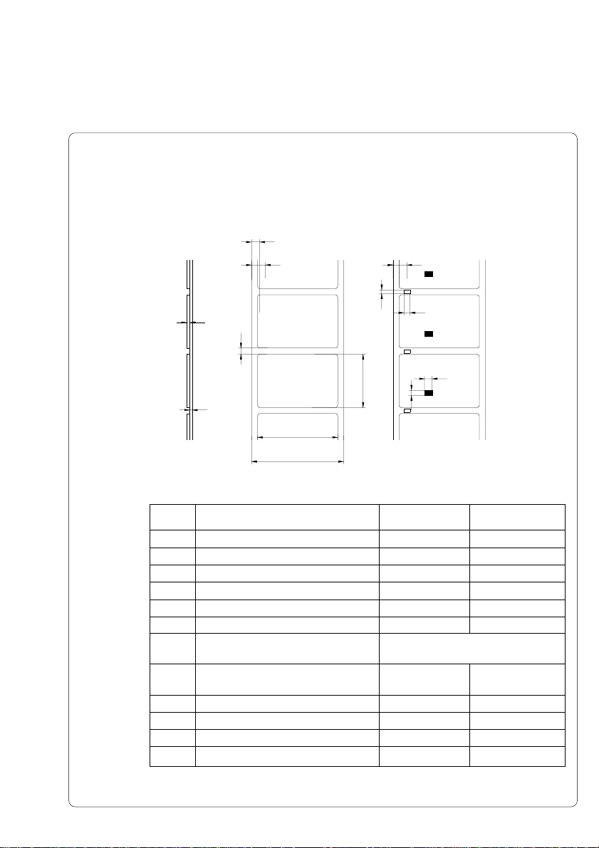
Label/ Tag Media Specifications
Label and tag media to be used for the Hermes can be found in the table
below. Note this information before ordering your labels.
G
H
E
D
H
K
I
C
F
A
B
Fig. 1 Label formats
Item MIN. MAX.
A Label width .4(10) 4.6(116)
B Width of the silicon liner .4(10) 4.7(120)
C Label length .2(5) 21.5(546)
D Gap between labels .08(2) 21.5(546)
E Label thickness .0024(.06) .01(.25)
F Thickness of silicon liner .002(.05) .004(.1)
G Distance of the first printing point
from the edge of silicon liner 0
H Distance of the label sensor
from the edge of silicon liner .08(2) 1.85(47)
I Width of punch hole .2(5) K Height of punch hole .08(2) .2(5)
L Width of reflective mark .2(5) M Height of reflective mark .08(2) .2(5)
L
M
Table 1 Label formats in inches (figures in brackets are in mm)
17cab - Produkttechnik GmbH
Page 18
Transfer Ribbon
The choice of a suitable transfer ribbon is important for the print quality of your
printer as well as the useful life of the printhead.
NOTICE !
Hermes 4N and Hermes 4F are equipped with a near edge printhead. For
that reason choose transfer ribbons which are especially designed for the
use with near edge printheads.By using other ribbons only a poor print
quality is reacheable. The printouts have no brilliance, the surfaces are
dull.
For Hermes 4F and Hermes 5F standard transfer ribbons are usable.
CAUTION !
Transfer ribbons of inferior quality may cause premature deterioration of
the printhead !
The material must be extremely resistant to high temperatures to avoid melting
the ribbon with the printhead.
The heat which arises during printing must be carried off by the label and by
the transfer ribbon itself. Transfer ribbons of inferior quality are often poor heat
conductors. This may cause overheating of the printhead in spite of electronic
protection.
Poor transfer ribbons also tend to lose parts of the coating which leads to
accumulating dirt on the printhead and the sensors. With some ribbons the
color rubs off and soils the printhead. All of these effects contribute to poor
print quality.
We have carried out numerous tests with many different ribbons and we
recommend you use transfer ribbons made by well-known/ brand
manufacturers only. Depending on the label material, several transfer ribbons
may be suitable.
The quality of print is determined by the right combination of these materials.
The recognition of the transfer ribbon is sensed by the rotation control of the
transfer ribbon unwinder, rather than by photocell sensors. As a result, ribbons
with a thinner coating or those with a colored coating can be used safely. To be
able to print all labels up to the exact end of the transfer ribbon, the length of
the uncoated trailer is limited.
NOTICE !
When buying transfer ribbons, make sure that
- the trailer of the ribbon has a maximum length of 4 in (100 mm).
- the trailer is made of nonconductive material of is coated with a
nonconductive film.
- the trailer easily can come loose from thecardboard core (F<3N).
18 cab - Produkttechnik GmbH
Page 19

2 General Safety Instructions
CAUTION !
- The printers of the Hermes series are built exclusively to print labels.
- Connect the printer only to an outlet with the correct voltage !
The printer is configured for either 230V or 115V power supply, which can
be switched using the input voltage selector at the back of the printer.
Connect only to a power outlet with a grounded contact.
- The printer must only be connected to devices which have extra low
voltage.
- Power must be OFF before plugging in any accessory or connecting the
printer to a computer, etc. Also switch power off on all appliances before
disconnecting.
- Do not expose the printer to any moisture, or use in damp or wet areas.
- The printer will operate with the cover open if necessary. This is not
recommended, as moving or rotating parts become accessible. Keep long
hair, jewelry, loose clothes away from the moving parts.
- During the print process the printhead will become hot. Use extra caution
when touching the printhead.
3 Delivery Contents
Inspect the Hermes packaging and contents immediately after receipt for
possible damage caused by shipping.
The supplied equipment of the Hermes depends on the requested options.
Compare the delivered accessories with your order.
NOTICE !
Please keep the original packaging in case the printer must be returned.
19cab - Produkttechnik GmbH
Page 20
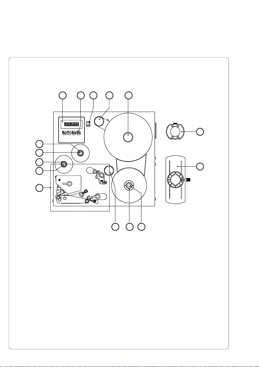
4 Printer Component Location
1 2 3 4
15
14
13
12
11
Fig. 4a Side view Hermes 4N
1 - Display
2 - Function keys with indicator LEDs
3 - Power switch
4 - Swing arm with guide roller
5 - Media supply hub
6 - Adapter
7 - Flange
8 - Knurled knob
9 - Media rewind hub
10 - Guide roller
11 - Print mechanism (Fig. 4e)
12 - Knurled knob
13 - Ribbon take up hub
14 - Knurled knob
15 - Ribbon supply hub
5
6
7
8910
cab - Produkttechnik GmbH20
Page 21
1 2 3 4 5 6
17
16
15
14
13
12
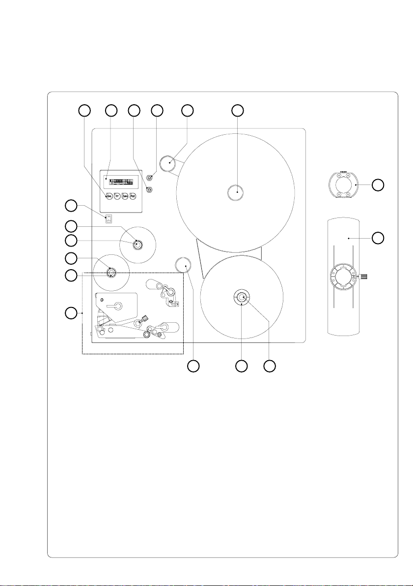
Fig. 4b Side view Hermes 5N
1 - Function keys with indicator LEDs
2 - Display
3 - Connector warning sensor transfer ribbon end
4 - Connector warning sensor label end
5 - Swing arm with guide roller
6 - Media supply hub
7 - Adapter
8 - Flange
9 - Knurled knob
10 - Media rewind hub
11 - Guide roller
12 - Print mechanism (Fig. 4e)
13 - Knurled knob
14 - Ribbon take up hub
15 - Knurled knob
16 - Ribbon supply hub
17 - Power switch
7
8
91011
21cab - Produkttechnik GmbH
Page 22
1 2 3 4
15
14
13
12
11
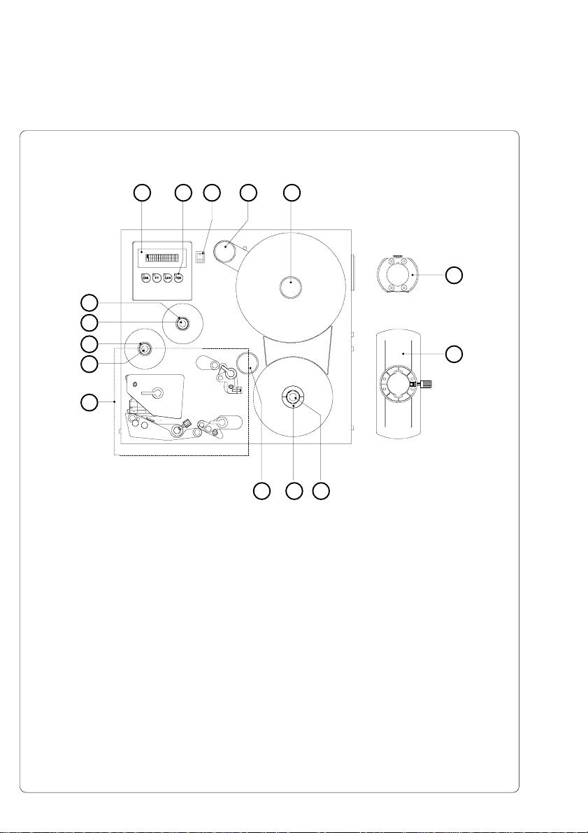
Fig. 4c Side view Hermes 4F
1 - Display
2 - Function keys with indicator LEDs
3 - Power switch
4 - Swing arm with guide roller
5 - Media supply hub
6 - Adapter
7 - Flange
8 - Knurled knob
9 - Media rewind hub
10 - Guide roller
11 - Print mechanism (Fig. 4f)
12 - Knurled knob
13 - Ribbon take up hub
14 - Knurled knob
15 - Ribbon supply hub
5
6
7
8910
cab - Produkttechnik GmbH22
Page 23

1 2 3 4 5 6
17
16
15
14
13
12
Fig. 4d Side view Hermes 5F
1 - Function keys with indicator LEDs
2 - Display
3 - Connector warning sensor transfer ribbon end
4 - Connector warning sensor label end
5 - Swing arm with guide roller
6 - Media supply hub
7 - Adapter
8 - Flange
9 - Knurled knob
10 - Media rewind hub
11 - Guide roller
12 - Print mechanism (Fig. 4f)
13 - Knurled knob
14 - Ribbon take up hub
15 - Knurled knob
16 - Ribbon supply hub
17 - Power switch
7
8
91011
23cab - Produkttechnik GmbH
Page 24

21
3
20
19
18
17
16
15
14
10111213
Fig. 4e Detailed view of the print mechanism Hermes 4N/5N
1 - Backfeed roller
2 - Backfeed system locking unit
3 - Backfeed system locking lever
4 - Locking screw for label track adjustment
5 - Set screw for label track adjustment
6 - Media guide with locking screw
7 - Media guide axle
8 - Transport system locking lever
9 - Transport system locking unit
10 - Transport roller
11 - Label edge sensor
12 - Knurled knob to adjust the label edge sensor
13 - Printhead levelling adjustment screw
14 - Print roller
15 - Socket of the peripheral port for cab-applicators
16 - Peel-off edge
17 - Thermal printhead
18 - Printhead locking lever
19 - Adjustable axle for ribbon track adjustment
20 - Locking screw for ribbon track adjustment
4
5
6
7
89
cab - Produkttechnik GmbH24
Page 25

21
3
21
20
19
18
17
16
15
8914
Fig. 4f Detailed view of the print mechanism Hermes 4F/5F
1 - Backfeed roller
2 - Backfeed system locking unit
3 - Backfeed system locking lever
4 - Locking screw for label track adjustment
5 - Set screw for label track adjustment
6 - Transport system locking lever
7 - Transport system locking unit
8 - Transport roller
9 - Media guide with locking screw
10 - Media guide axle
11 - Label edge sensor
12 - Knurled knob to adjust the label edge sensor
13 - Printhead levelling adjustment screw
14 - Print roller
15 - Socket of the peripheral port for cab-applicators
16 - Peel-off edge
17 - Ribbon shield
18 - Thermal printhead
19 - Printhead locking lever
20 - Adjustable axle for ribbon track adjustment
21 - Locking screw for ribbon track adjustment
4
5
6710111213
25cab - Produkttechnik GmbH
Page 26

1
7
2
3
4
5
6
Fig. 4g Rear view
1 - Input voltage selector / Fuse holder
2 - Input voltage selector cover
3 - Power supply connector
4 - Connector warning sensor transfer ribbon end (Hermes 4N/4F only)
5 - Connector warning sensor label end (Hermes 4N/4F only)
6 - Connector warning light
7 - Drillings for mounting a compressed air service unit (option)
8 - Memory card module slot
9 - Drillings for mounting a bracket (option)
10 - Parallel interface port
11 - Serial interface port
12 - Plug of the peripheral port for non-cab-applicators
8
9
10
11
12
cab - Produkttechnik GmbH26
Page 27

27cab - Produkttechnik GmbH
Page 28

5 Connecting the printer
Connection to Power Supply
The Hermes is designed for use with 230V A.C/50 Hz (standard) or 115V A.C/
60 Hz.
CAUTION !
Before connecting the printer to the power supply, make sure that the
voltage selected on the power supply module of the printer is the same as
your main power supply ! Pay attention that the power switch (4/5) is in
position "O" (OFF).
1
2
3
5
1 - Voltage selector
2 - Cover
3 - Power supply connector
4 - Power switch Hermes 4N/4F
5 - Power switch Hermes 5N/5F
6 - Fuses
Fig. 5a Power supply module / power switch
To change the voltage setting, open the cover (2) and remove the voltage
selector (1) from the power unit.
CAUTION !
If you have changed the operating voltage of your printer the fuses (6)
need replacing as stated below !
230V - 2 x T 4A 115V - 2 x T 6,3A
When delivered, the correct fuses for the pre-selected operative voltage are
installed. You will find the necessary fuses for the other voltage in the
accessories package. Slide the voltage selector back into the power supply
module so that the correct voltage is visible in the lid window of the cover (2).
Connect the printer to a grounded outlet using the power cable supplied in the
accessories package.
4
6
1 6
cab - Produkttechnik GmbH28
Page 29

Connection to a Computer
Hermes is equipped with three serial interfaces, these are RS-232, RS-422,
and RS-485, all of them using the 25 pin interface connector (2) at the back.
In most cases, you can use the RS-232 interface for the connection to the
computer. If your computer is located more than 50 ft (15 m) away from the
printer you should use the RS-422 interface.
The RS-485 interface is provided for using the Hermes as part of a networked
system.
In addition to the serial port, the Hermes also provides a parallel (Centronics)
interface which offers a faster transfer of data than the serial interfaces.
Therefore, we recommend you use the parallel interface for those applications
where a large number of loadable fonts or complex graphics have to be printed.
For the Centronics interface use the 36 pin interface connector (1).
Select the required interface settings using the Setup procedure and connect
the printer to the computer by a suitable interface cable.
CAUTION !
Make sure that all connected computers and their connecting cables are
correctly grounded.
1
2
Fig. 5b Interface ports (rear view of the printer)
1- Parallel interface port
2- Serial interface port
29cab - Produkttechnik GmbH
Page 30

Switch on the printer
2
Fig. 5c Switch on the printer
After making all connections switch on the printer at the power switch (1/2).
The printer carries out a short system test and following the display is shown
the system mode "ONLINE".
If a hardware failure occurs during the system test the type of the failure will be
shown. In this case the printer should be switched off and on again. If the
failure occurs again call the service.
If the display is not showing anything after switching on the printer, please
check the following whether:
- the connection of the power switch is correct
- the setting of the voltage selector corresponds with the power supply voltage
- the fuses in the voltage selector are not defective
1 - Power switch Hermes 4N/4F
1
2 - Power switch Hermes 5N/5F
If all these conditions are true and the device nevertheless cannot be switched
on call for service, please.
CAUTION !
If the fuses in the voltage selector are defective do not use the fuses of
the delivery contents as spare parts.
These fuses are only for using at the other operation voltage.
By using the fuses of the delivered contents without changing the setting
of the voltage selector, the printer may be damaged.
cab - Produkttechnik GmbH30
Page 31

6 Media loading
Preparation of the label supply hub
1 2 3 4 2 3
Fig. 6a Preparation of the label supply hub
Hermes is equipped with a rotating label supply hub, which is able to take up
rolls with a core diameter of 3 in (76 mm).
To take up these label rolls it is necessary to mount two adapters (3) onto the
supply hub :
1. Put the first adapter (3) onto the supply hub (4) and slide it to the wind plate
(1) until it blocks. Tighten the knurled srew (2).
2. Put the second adapter onto the supply hub (4) and slide it against the
wind plate until the distance between the outer edge of the adapter and the
wind plate (1) is a little less than the width of the label roll. Tighten the
knurled screw.
31cab - Produkttechnik GmbH
Page 32

Loading Labels
19
18
17
16
15
1 2 3 4 5
10
Fig. 6b Media loading Hermes 4N/5N
1. Place the label roll (1) onto the prepared media hub (3) and slide it against
the wind plate (5). The solid line represents the feed path of outside-rolled
labels, the broken line of inside-rolled labels.
2. Put the flange (4) on the supply hub (3), slide it against the label roll (1) and
fix it at the supply hub by tightening the knurled knob (2).
3. Swing the three levers (9, 19 und 16) clockwise until they stop and open
this way the transport system (10,11) and the backfeed system (17,18).
The printhead (15) also will be unlocked from the print roller.
4. Loosen the knurled knob (12) and slide the media guide (13) into its
outermost position.
678911121314
cab - Produkttechnik GmbH32
Page 33

16
15
10 911121314
Fig. 6c Media loading Hermes 4F/5F
5. Unroll a length of label stock from the media roll and feed it first to the
printhead (15) as shown in figure 6b.
NOTICE !
It is particularly important to ensure that the media strip slides properly
between the fittings of the adjustable photocell assembly (14).
6. Feed the label stock out of the front side of the printer until there is enough
material to reach the internal rewinder. Take all labels off the outstanding
liner, and feed the liner as shown in figure 6b to the internal rewinder (8).
7. Slide the media strip under the rewinder clamps (6) to the wind plate. Hold
the rewinder and turn the knurled knob (7) clockwise. That way the label
strip will be fixed at the rewinder.
8. Turn the rewinder (8) clockwise for tightening the label strip.
9. Slide the guide (13) against the outer edge of the label strip and tighten the
knurled knob (12).
10. Swing all levers (9, 19 and 16) counterclockwise until they block. In this
way the transport system (10,11) and the backfeed system (17,18) will be
closed and the printhead (15) will be locked.
NOTICE !
If you do not use the printer for an extended period of time, lift the
printhead to avoid possible flattening of the print roller.
33cab - Produkttechnik GmbH
Page 34

Loading Transfer Ribbon
6
1
2
3
4
5
Hermes 4N/5N Hermes 4F/5F
Fig. 6d Loading thermal transfer ribbon
1. To lift the printhead (5), turn the printhead lever (4) clockwise until it stops.
2. Slide the roll of transfer ribbon (6) onto the ribbon supply hub (7) as far as
possible.
NOTICE !
Pay attention to the side of the ribbon material which is coated with ink !
The inked side is generally the dull side. When the ribbon is inserted, the
inked side must face the opposite side of the printhead !
In Figure 6c, the solid line shows the path of inside wound ribbon, and
the broken line represents the path of outside wound ribbon.
3. Hold tight the ribbon supply hub (7) and rotate the knurled knob (8)
clockwise until it stops. That way the transfer ribbon roll (6) will be attached
to the ribbon supply hub (7).
4. Slide an empty cardboard core (1) onto the ribbon take up hub (2) and fix it
by clockwise turning the knurled knob (3).
5. From the side, feed the transfer ribbon along the path as shown in
Figure 6d, then attach it to the core (1) using adhesive tape or a label.
6. Turn take up hub (2) counterclockwise in order to smooth and stretch the
ribbon.
7. To lock the printhead (5), turn the lever (4) counterclockwise until it stops.
7
8
1
2
3
4
5
6
7
8
cab - Produkttechnik GmbH34
Page 35

7 Adjustments Concerning the Labels
Adjustment of the Label Edge Sensor
21 2 1
Hermes 4N/5N Hermes 4F/5F
Fig. 7a Adjustment of the label edge sensor
To accommodate a variety of print jobs, the position of the label edge sensor
(2) can be adjusted cross to the path of the paper feed. This setting is
particullary usefull if the required labels are either narrow, or have punch holes
or reflective markings, or deviate from the square or rectangular shape.
It is important to ensure that the sensor is positioned in a way that the gaps
between the labels or the markings can be recognized by the photocell. (The
position of the sensor is marked by a notch in the sensor holder.)
If using labels with an unconventional shape (i.e. round or curved) the sensor
should be positioned at the front edge of the label.
Adjust the sensor position using the knurled knob (1).
By turning the knob clockwise the sensor moves outward, and by rotating the
knob anticlockwise it moves inwards.
35cab - Produkttechnik GmbH
Page 36

Adjustment of the Printhead Support
2 3b
3a14
Hermes 4N/5N Hermes 4F/5F
Fig. 7b Adjustment of the printhead support
When printing narrow labels (label width less than the half of the maximum
print width), it is possible that the printhead will come into direct contact with
the drive roller. This will lead to premature wear on the printhead. In addition,
the printhead will be at a slight angle to the label, thus, the uneven pressure
may result in an inconsistent image density from one edge of the label to the
other.
To correct this problem, the printhead support (2) may be adjusted.
Adjust printhead support as follows :
1. Loosen the knurled screw (3).
2. Move the knurled screw (3) as required within the adjustment slot (4). This
will cause the cam shaped printhead support (2) to rotate, in effect,
providing a higher or lower base on which the printhead mounting (1) rests.
3. It is convenient to use the position 3a to print large labels. In this case the
printhead support (2) is totally inactiv.
4. By using small labels it is necessary to adjust the printhead support. In this
case insert a second strip of the label at the front side of the print roller.
Now slide the knurled knob (3) as far as possible to position 3b in the
adjustment slot (4), until the printhead support (2) touches the printhead
mounting (1). Take away the second label strip.
5. Tighten the knurled screw (3).
2 3b
3a14
cab - Produkttechnik GmbH36
Page 37

Adjustment of the Label Tracking
1 2 3
Fig. 7c Adjustment of the label tracking (backfeed system)
It is necessary to adjust the label tracking, if the label strip sideward leaves the
normal path.
Such a drift may cause :
- a sideward displacement of the printed images at the label.
- a sideward displacement of the peel position.
- a paper jam or a damage of the label strip.
To correct this problem, the backfeed system may be adjusted as follows :
1. Loosen the locking screw (2) at the backfeed system.
2. Adjust the label tracking by turning the set screw (3).
If the labels drift inwards ð Turn the set screw clockwise.
If the labels drift outwards ð Turn the set screw counterclockwise.
Repeat the adjustment as long as necessary. After every adjustment step
open and close the backfeed system by turning the lever (1).
3. Tighten the locking screw (2).
37cab - Produkttechnik GmbH
Page 38

Adjustment of the Transfer Ribbon
1
2
3
4
Hermes 4N/5N Hermes 4F/5F
Fig. 7d Adjustment of the transfer ribbon
If creases, lines or black patches appear in the print image resulting in a poor
print quality, this may be caused by wrinkles in the transfer ribbon (4). To
remove the wrinkles, the tension of the ribbon should be made even from the
left to the right by slanting the axle (1).
1. Loosen the locking screw (2).
2. The axle may be slanted by moving the locking screw (2) as required inside
the adjustment slot (3). Moving it to the bottom will tightened the ribbon on
the inner edge. In the other case it will be done on the outer side of the
transfer ribbon.
To reduce the formation of wrinkles the ribbon must be tightened at this
side where the wrinkles will be built
1
2
3
4
3. After completing the adjustment, tighten the locking screw (2).
cab - Produkttechnik GmbH38
Page 39

8 Options
Applicators
Non-cab-Applicators
The Thermal Transfer Printers of the Hermes family are especially developed
for fully automatic labelling. Therefore all types of Hermes are equipped with a
peripheral port with a minimum configuration of signals. That way it is possible
to operate many different non-cab-applicators at the Hermes.
Fig. 8 a Peripheral port for non-cab-applicators
For the use of Hermes with a non-cab-applcator two input signals are needed :
1. "Print start"
Since the label will be dispensed from the liner directly after printing, it is
necessary to make sure, that the applicator is ready to take the label when
sending the signal "Print start".
1
2. "Label is taken"
This signal is needed to start the backfeed of the label material. After the
backfeed the print of the next label can be started from the front edge.
It is also necessary to activate this signal, if the parameter "Backfeed" in
the setup is set to "smart". Otherwise the next "Print start" signal will not be
accepted.
Beside the described input signals it is possible to get some status information
via the peripheral port.
The complete interface description is included in the appendix B.
39cab - Produkttechnik GmbH
Page 40

cab-Applicators
Fig. 8 b cab-Applicators for Hermes
1 2 3 4
cab offers a own line of applicators (1) for the printers of the Hermes family. To
connect these applicators the cab-types of Hermes have aditionally a second
peripheral port (3) at the front side.
Typically for the cab-applicators, the dispensed label will be taken by a vacuum
plate (2). After that different pneumatic cylinders move the plate to the labelling
position where the label will be pressed or blown onto the product.
The size of the vacuum plate is specified for the label size.
40 cab - Produkttechnik GmbH
Page 41

The following table shows some standard versions of cab-applicators :
Applicator type Labelling destin. Labelling type
Tamp Applicator downwards press on
with Lift Cylinder
Tamp Blow Applicator downwards blow on
with Lift Cylinder
Tamp Applicator sidewards press on
with Swing & Lift Cylinder
Blow Applicator sidewards/ blow on
with Swing Cylinder upwards
Table 8 cab-applicator types
For use in a networked system all cab-applicators are equipped with a PLC
interface with potential free inputs and outputs .
For the detailled description of the cab-applicators several Operator's Manuals
are available.
41cab - Produkttechnik GmbH
Page 42

Bracket
The delivery program of the Hermes series includes brackets for Hermes 4
and Hermes 5. These mounting elements allow to hang in the printer in to a
production line. For that the bracket first must be mounted onto a profile.
After that the printer can be hung in into the bracket and fixed by screws.
The delivery contents of the bracket (1) include a clamp (2) for mounting the
bracket (1) at a profile with a cross-section of 50mmx50mm. The clamp is
made of three parts assembled by screws (3).
1 2 3
Fig. 8 c Bracket with clamp
The form of the clamp allows to mount the bracket onto a horizontal as well as
a vertical profile. Besides the bracket can be moved sideward inside the
clamp. This way the bracket can be adjusted to different centers of gravity
when differnt applicators are used at the Hermes.
Fig. 8 d Samples of the bracket mounting
42 cab - Produkttechnik GmbH
Page 43

4
1
5
Fig. 8 e Mounting the printer at the bracket
Hermes has one each bolt (4) at the front and the rear side. Using these bolts
the printer is hung in into the grooves of the bracket (1). After that the printer is
fixed at the bracket with six screws (5).
43cab - Produkttechnik GmbH
Page 44

Feet
Using the profile feet Hermes can be put directly on a table. Its also possible to
mount the printer onto a customer specific head plate.
The feet are fixed from below with four screws at the frame of the printer. The
shorter foot has to be mounted below the print machanism.
Fig. 8 f Feet
Fig.8 g Set up the printer on a table
Fig. 8 h Set up the printer on a head plate
44 cab - Produkttechnik GmbH
Page 45

Warning Light
By using the warning light it is possible to recognize the state of the printer with
one view.
For mounting the warning light it is recommended to use the option "Bracket".
Fig. 8 i Connection of the warning light
1. Fix the warning light (1) at the bracket (3). Use the two screws (2) which
1
2
3
4
5
are included in the delivery contents of the light.
2. Contact the connection cable (4) of the warning light at the socket (5).
During the operation the lamps have following functions :
green Device is switched on, voltage is available.
yellow Warning : labels respectively transfer ribbon have passed the
preset minimum quantity.
Function is only available when the warning sensor label end is
mounted.
red Printer error
Further information about the kind of error is shown at the display.
45cab - Produkttechnik GmbH
Page 46

Warning Sensors
The sensors recognize, when the diameter of the label supply roll respectively
the transfer ribbon roll decreases below a preset thresould value.
NOTICE !
The messages of the sensors are only intended to inform the operator.
They do not influence the operation of the Hermes, i.e. the operation is
not interrupted.
The messages will be shown by switching on the yellow lamp of the warning
light (option). The signals also can be sent to a control system by using the
peripheral interface.
Warning Sensor Label End
Mounting
1. Switch off the printer
2. Slide the sensor holder (1) with the warning sensor label end (2) behind the
wind plate (6) of the media supply hub.
3. Attach the sensor holder with the slotted head screw (7) and the hexagon
socket head screw (3) to the mounting plate. The hexagon socket head
screw (3) must be used at this side, where the elongated hole is located in
the sensor holder.
4. Plug the cable (4). For that Hermes 4 has a 5-pin connector at the rear
side of the frame. The connector (10) at Hermes 5 is beside the control
panel.
Adjustment
With this setting the threshold diameter (3.3 to 4.3 in / 84 to 110mm) for the
warning message can be adjusted.
1. Slide a label roll (9) with the intended threshold diameter onto the media
supply hub.
2. Switch on the printer. The sensor (2) sends out a beam (5). If the label roll
does not interrupt the path of the beam, the beam is mirrored at the
reflective foil (8) and detected again by the sensor. In that case the LED at
the sensor is on.
3. Loosen the hexagon socket head screw (3) and swing the sensor holder
against the axle of the media supply hub as near as possible.The LED at
the sensor is off.
4. Slowly swing the sensor holder away from the axle until the LED at the
sensor goes on.
5. Tighten the hexagon socket head screw (3).
46 cab - Produkttechnik GmbH
Page 47

1 2 3 4 5
Fig. 8 k Warning sensor label end Hermes 4
10 4 2 7 1 6
6
7
8
9
4
Fig. 8 l Warning sensor label end Hermes 5
5
8
3
9
47cab - Produkttechnik GmbH
Page 48

Warning Sensor Ribbon End
NOTICE !
The warning sensor ribbon end is analyzed by the printer electronics only
if the warning sensor label end is installed too.
Mounting
1. Switch off the printer
2. Attach the sensor holder (7) with the warning sensor ribbon end (8) using
the screws (6) to the mounting plate.
3. Plug the cable (9). For that Hermes 4 has a 3-pin connector at the rear
side of the frame. The connector (10) at Hermes 5 is beside the control
panel.
4. The contents of delivery include a reflective foil (2).
Remove the covering foil from the glued surface an stick the reflective foil
(2) onto the bracket (3) below the ribbon hubs as shown in fig.8m. Make
sure that the distance between the reflective foil and the mounting plate (1)
is about 0.6in (15mm).
Fig. 8 m Placing the reflective foil
15
15
1
2
20
3
Adjustment
With this setting the threshold diameter (1.4 to 1.6in / 34 to 41mm) for the
warning message can be adjusted.
1. Slide a transfer ribbon roll (4) with the intended threshold diameter onto the
media supply hub.
2. Switch on the printer. The sensor (8) sends out a beam (5). If the ribbon roll
does not interrupt the path of the beam, the beam is mirrored at the
reflective foil (2) and detected again by the sensor. In that case the LED at
the sensor is on.
3. Loosen the screws (6) and move the sensor holder to the right as far as
possible.The LED at the sensor is off.
4. Slowly move back the sensor holder to the left until the LED at the sensor
goes on.
5. Tighten the screws (6).
48 cab - Produkttechnik GmbH
Page 49

76 98
5
4
2
3
Fig. 8 n Warning sensor ribbon end Hermes 4
10
9
8
6
7
4
5
2
3
3
Bild 8 o Warning sensor ribbon end Hermes 5
49cab - Produkttechnik GmbH
Page 50

50 cab - Produkttechnik GmbH
Page 51

9 Control Panel
The front control panel of the Hermes is fitted with 4 function keys with
indicator LEDs, and a 2x16 character digital LCD display.
Fig. 9 Control Panel
The control panel display constantly provides the operator with the actual
information concerning the current printer mode and label processing. The
indicator LEDs support the information shown in the display by indicating which
keys have to be pressed. (e.g. in the event of a fault)
On the following pages, you will find descriptions of the system modes of the
Hermes, the related indications by the LCD display an the LEDs as well as a
description of the function keys under differing conditions.
51cab - Produkttechnik GmbH
Page 52

System Mode ONLINE
ONL key Switch into OFFLINE mode (LED ONL off)
FF key Provides label feed. The leading edge of the next label to be
CAN key Deletes data of the previous print job in internal memory.
PSE key Repeats the print of the last label, after the previous print job has
ONL key Pressing both keys together for at least 5 seconds will switch
+ into the SETUP mode.
CAN key (LED ONL off)
printed is in print position.
Following that, "Pause reprint" is not available.
(see PSE key)
been completed. (only if setup parameter 'Pause reprint' is on)
System Mode OFFLINE
ONL key Switch into ONLINE mode (LED ONL on)
FF key Provides label feed. The leading edge of the next label to be
CAN key Switch into LABEL FROM CARD mode.
PSE key Display shows current printer mode
printed is in print position.
(only if memory card is installed and formats are stored it)
System Mode PRINT
CAN key short pressing : Cancels the current print job,
longer pressing (>1s): Cancels the current print job,
PSE key Interrupts the current print job,
Switch into PAUSE mode (LED PSE on)
52 cab - Produkttechnik GmbH
Switch to the next job in the input buffer
Deletes the input buffer
(LED CAN blinks),
Switch into ONLINE mode
Page 53

System Mode P AUSE
FF key Provides label feed. The leading edge of the next label to be
CAN key Cancels the current print job,
PSE key Continues the current print job,
printed is in position.
Switch into ONLINE mode (LED PSE off)
Switch into PRINT mode (LED PSE off)
System Mode LABEL FROM CARD
ONL key Switch into OFFLINE mode
FF key For scrolling down within the file list stored on the card.
CAN key For scrolling up within the file list of the card.
PSE key Confirms file selection.
Reduces the quantity of labels to be print.
Increases the quantity of labels to be printed.
Moves the cursor to be right when setting the quantity of labels
to print.
Switch into PRINT mode
53cab - Produkttechnik GmbH
Page 54

10 Setup
This mode is initiated by either simultaneously pressing the key and the
system test is completed, or in ONLINE mode, press the same two keys down
for at least 5 seconds.
In this mode a lot of printer parameters could be adapted to the concrete using.
The setup mode can be left at any point by pressing the key.
The confirmed parameters will be saved.
To return to the original factory default settings, press all three keys, the
key, the key, and the key simultaneously and keep them pressed
down until the display shows "--- RESTORE ---".
Function keys in the SETUP mode
key when switching on the printer and keep them pressed down until the
ONL key Stores the chosen settings of the setup-parameters and
FF key Skips to next setup parameter.
CAN key Skips to previous setup parameter.
PSE key Confirms selected settings for parameters.
54 cab - Produkttechnik GmbH
completes the SETUP mode.
(i.e. switch into ONLINE mode (LED ONL on)
Reduces numerical setup values.
Increases numerical setup values.
Page 55

Overview of the Setup Parameters
Country Deutschland France
Schweiz Suisse Belgie Suomi
Italia España
United Kingdom
Ceska republika
Transfer print On Off
Label sensor Gap sensor
Interface RS-232C RS-422 RS-485 Centronics
Peel position + y.y mm - y.y mm
Printhead position X: ?.x mm Y: + y.y mm Y: - y.y mm
Baud rate Baud rate Baud rate
Protocol Protocol
± ?.y mm ± ?.y mm
± y.? mm ± y.? mm
X: x.? mm Y: ± ?.y mm Y: ± ?.y mm
Bottom-Reflect
Y: ± y.? mm Y: ± y.? mm
Top-reflect
Network address
Heat level + h - h
Printer info Version xxxxx xxx m / xxx h
Set date DD.00.0000 00.MM.0000 00.00.YYYY
Set time hh.00.00 00.mm.00 00.00.ss
Character set
ISO 8895-1 Codepage 850 EBCDIC Macintosh
Codepage 852 ISO 8895-8 Windows 1252 Windows 1250
Format card No Yes
Copy memory card Yes No
Backfeed
head lift-off* head down* * Selection "head down" only possible at Hermes 4F/5F
smart always
USA
Danmark
Debug mode Off On
Pause reprint On Off
55cab - Produkttechnik GmbH
Page 56

11 Error Messages / Problem Solution
Correctable Errors
While processing a print job, an error has occured which may be corrected by
the operator, and also allows you to continue the print job after fault correction.
Display : The top line of the display shows alternately the type of fault
LED Display : LED CAN on, LED PSE is flashing.
Function Keys
CAN key Cancels the current print job.
PSE key Continues current print job after error correction.
Irrecoverable Errors
While switching on the printer or during printing, a fault has occured which
cannot be cleared by the operator without cancelling the current print run
(e.g. hardware fault).
Display : This display shows the type of fault.
LED Display : LED CAN is flashing.
Function Keys
and the total of the remaining labels of the current print job.
Switch into ONLINE mode.
(LED ONL on, LED CAN off, LED PSE off)
Switch into PRINT mode.
(LED ONL on, LED CAN off, LED PSE off)
Taste CAN Cancels the current print job.
56 cab - Produkttechnik GmbH
Switch into ONLINE mode.
(LED ONL on, LED CAN off, LED PSE off)
If ONLINE mode cannot be entered, switch printer on and off
again.
If the fault remains again, contact Technical Service.
Page 57

Appendix A - Built-in Dimensions
The devices of the Hermes-family are prepared to build in an assembling line.
For that reason there will be offered a fitting clamp for the hanging mounting
and in the other case feet for a standing mounting.
Of course you are able to order Hermes without any options and use own fitting
elements.
Certainly by ordering the option clamp the fitting holes for the mounting of the
warning light (option), a compressed air service unit for the pneumatic
applicator and standard mounting elements (e.g. flange FKV 50 respectively
profile EV 50 of the firm Rose&Krieger Verbindungstechnik GmbH) will be
delivered.
The feet of Hermes are shaped in such a way that the printer may be fitted at
the setting area with suitable clamps and so the Hermes will be saved against
sliding.
CAUTION !
If you have purchased the printer without feet, avoid to place it upright.
Due to the missing feet, the printer may fall on its front side, where its
own weight rests on the print mechanism. This may cause damage to the
printer.
The drawings at the next pages show the most important function dimensions
to integrate the Hermes :
Page A-2 : Hermes 4N
Page A-3 : Hermes 4F
Page A-4 : Hermes 5N
Page A-5 : Hermes 5F
cab - Produkttechnik GmbH A-1
Page 58

s
f
277
113
89
55.5
22
4
420
157
o
3xM6 on both sides
223 36
43
220
16
2
4xM5 on the bottom
7.8
55.4
1
10
27
33443
50
17
2.5
3
490
390
164
97.5
252.5
77
1
212
42.7
128
28
245.7
245.7
1
Bracket
et
5942471
71
2
Feet
5537748
48
3
Compressed air servi ce
ressed air service unit
4
Tamp Applicator with Li
Applicator with Lift Cylinder Type 1100-220 H
5537950
50
15max.120
18
Transfer Printer Herme
fer Printer Hermes 4N
5537500
00
A-2cab - Produkttechnik GmbH
Page 59

d
277
113
89
55.5
22
4
420 157
o
3xM6 on both sides
36
223
55
220
16
2
7.72
55.4 27
1
10
33443
o50
17
2.5
3
1
502
390
212
42.7
128
128
245.7
245.7
152
1
Bracket
ket
5942471
2471
2
Feet
158
98
t
5537748
7748
3
Compressed air service unit
pressed air service unit
4
Tamp Applicator with Lift Cylin
4xM5 on the bottom
15max.120
7718
p Applicator with Lift Cylinder Type 1100-220 H
5537950
7950
Transfer Printer Hermes 4F
nsfer Printer Hermes 4F
7503
5537503
A-3cab - Produkttechnik GmbH
Page 60

277
113
89
55.5
22
4
3xM6 on both sides
542
457
o
542
3
1
490
230 36
43
220
7.87.8
2
1
15
max.120
10
55.4
27
457
33443
50
2.5
16
17
164
253
193
7718
219
43
42.7
128
128
245.7
245.7
1
Bracket
et
5942472
472
2
Feet
5537748
748
3
pressed air service unit
Compressed air service unit
4
Tamp Applicator with Lift Cylinder Type 1
Applicator with Lift Cylinder Type 1100-220H
5537950
950
fer Printer Hermes 5N
Transfer Printer Hermes 5N
5537501
501
A-4cab - Produkttechnik GmbH
Page 61

277
113
89
55.5
22
4
3xM6 on both sides
502
457
o
542
3
1
542
230 36
55
220
2
1
15
max.120
10
55.4
27
457
33443
50
2.5
16
17
152
253
193
7718
219
42.7
128
8
245.7
245.7
1
Bracket
5942472
2
Feet
5537748
3
4
sed air service unit
Compressed air service unit
Tamp Applicator with Lift Cylinder Type 1
plicator with Lift Cylinder Type 1100-220H
5537950
Printer Hermes 5F
Transfer Printer Hermes 5F
5537506
A-5cab - Produkttechnik GmbH
Page 62

Appendix B - Pin Assignment of the Interface Connectors
Pin Assignment of the Serial Interface Connectors
Hermes provides a 25 pin SUB-D connector for the serial interfaces which are
internally available, i.e. RS-232, RS-422 and RS-485.
Pin 1Pin 13
Pin 14Pin 25
Fig. B-1 Connector of the serial interface (rear of the printer)
Pin Signal Function
1 CG Protective Ground
2 TxD Transmit Data (RS-232)
3 RxD Receive Data (RS-232)
4 RTS Request to send
5 CTS Clear to send
7 GND Logic Ground
9 TDATA+ Transmit Data (RS-422, RS-485)
10 TDATA- Transmit Data (RS-422, RS-485)
18 RDATA+ Receive Data (RS-422, RS-485)
19 RDATA- Receive Data (RS-422, RS-485)
20 DTR Data Terminal Ready
Table B-1 Signals of the serial interface connector
cab - Produkttechnik GmbH B-1
Page 63

Interface Cable for RS-232
The following chapter shows some typical RS-232 interface cable configurations. Note, that the pin assignment may vary for different computers. If you
have any problems with the connections, contact the manufacturer of your
computer on the pin assignment of the interface. Use the pin assignment of the
printer as shown in Table B-1 to obtain a suitable cable.
PC Hermes
11
23
32
520
77
64
85
20
25 pin connector 25 pin plug
Fig. B-2 Interface cable with 25 pin computer connector
for RS-232 with protocol " ---" or "XON/XOFF"
PC Hermes
22
33
57
820
14
45
6
9 pin connector 25 pin plug
Fig. B-3 Interface cable with 9 pin computer connector
B-2 cab - Produkttechnik GmbH
for RS-232 with protocol " ---" or "XON/XOFF"
Page 64

PC Hermes
11
23
32
45
54
77
6
8
20
25 pin connector 25 pin plug
Fig. B-4 Interface cable with 25 pin computer connector
Fig. B-5 Interface cable with 9 pin computer connector
for RS-232 with protocol " RTS/CTS" or "XON/XOFF"
PC Hermes
22
33
57
75
84
1
4
6
9 pin connector 25 pin plug
for RS-232 with protocol "RTS/CTS" or "XON/XOFF"
Interface Cable for RS-422 / RS-485
To control the Hermes by RS-422/ RS-485 interface, only the signals TDATA+,
TDATA-, RDATA+, and RDATA- are necessary.
Check the pin assignment for the interface of your computer, and use the pin
assignment of the printer as shown in table B-1 to obtain a suitable cable. The
connectors of TDATA+ and RDATA+ as well as TDATA- and RDATA- at the
plug-in-connection of the cable must be united. If there is a very large transfer
distance a termination of the cables is recommended.
cab - Produkttechnik GmbH B-3
Page 65

Pin Assignment of the Parallel Interface Connector
Hermes provides a 36 pin connector for the parallel Centronics interface.
Pin 18 Pin 1
Pin 19Pin 36
Fig. B-6 Centronics interface connector (rear of the printer)
Pin Signal Pin Signal Pin Signal Pin Signal
1 /STROBE 10 /ACKNLG 19 GND 28 GND
2 DATA 1 11 BUSY 20 GND 29 GND
3 DATA 2 12 PE 21 GND 30 GND
4 D ATA 3 13 SLCT 22 GND 31 nc
5 DATA 4 14 nc 23 GND 32 nc
6 DATA 5 15 nc 24 GND 33 nc
7 DATA 6 16 GND 25 GND 34 nc
8 DATA 7 17 nc 26 GND 35 nc
9 DATA 8 18 nc 27 GND 36 nc
Table B-2 Signals of the Centronics interface
Centronics Interface Cable
The cables used for Centronics interface connectors are standard cables, so
that normally there are no problems with the external control of the Hermes.
In the event of any difficulties, consult the manufacturer of your computer on
the pin assignment of the computer's interface. Use the pin assignment of the
printer as shown in Table B-2 to obtain a suitable cable.
B-4 cab - Produkttechnik GmbH
Page 66

Pin Assignment of the Peripheral Connector for Non-cab-Applicators
Hermes has a 15 pin SUB-D plug at the rear side. The signal set of this
interface includes on the one hand the signals needed to couple a non-cabapplicator and on the other hand status signals of the warning sensors "label
end" and "ribbon end".
All inputs and output are potential-free.
CAUTION !
This interface is not designated to couple a cab-applicator.
For the use of cab-applicators the Hermes printers have an additional
interface with a 15 pin SUB-D socket at the front side.
Pin 1 Pin 8
Pin 15Pin 9
Fig. B-7 Plug of the Peripheral Connector
Pin Direction Description
1 output printer not ready
2 output label is printed
3 output printer error
4 output print job available
5 output green (device is switched on)
6 input external error
7 input label was taken
8 input print start
9 output warning transfer ribbon end
10 (output) reverse line (for all output signals)
11 output warning label end
12 output label in present position
13 (input) external error (reverse line)
14 (input) label was taken (reverse line)
15 (input) print start (reverse line)
Table B-3 Pin-Assignment of the Peripheral Connector Plug
cab - Produkttechnik GmbH B-5
Page 67

Circuit Diagram of Inputs and Outputs
The inputs are optocouplers with a current limiting resistor of 2.4kΩ in the
input circuit.
[IN]
[IN]R
Fig. B-8 Circuit of the inputs
For each signal [IN] there is a separate reverse line [IN]R via the plug
connector. From that the following pairs of signals result :
[IN] Pin [IN] Pin [IN]R
Print start 8 15
Label was taken 7 14
External error 6 13
Table B-4 Pairs of input signals
All outputs are switched by relays which all have one common reverse line
(PIN 10 of the the plug).
[OUT]
Reverse line (Pin10)
Fig. B-9 Circuit of the outputs
Electrical requirements : U
= 42 V
max
I
= 100 mA
max
B-6 cab - Produkttechnik GmbH
Page 68

Comments to the signals
Printer not ready
There is an error by operating of the Hermes or the printer is OFFLINE.
The print of a label requires the readiness of the printer.
If the signal is active, the relay in the output circuit is closed.
Label is printed
At this time Hermes prints a label.
If the signal is active, the relay in the output circuit is closed.
Printer error
There is an error in the operation of the Hermes.
The details and type of error can be learnt from the printer display.
('Ribbon out'; 'Paper out'; 'No label')
If the signal is active, the relay in the output circuit is closed.
After error correction, the print of the last label will be repeated.
The error activates the signal 'Printer not ready', too.
Print job is available
Hermes has a print job (requirement to print a new label).
If the signal is active, the relay in the output circuit is closed.
Green
The voltage at the Hermes is switched on.
If the signal is active, the relay in the output circuit is closed.
The green lamp of the warning light is compatible to the signal 'Green'.
cab - Produkttechnik GmbH B-7
Page 69

External error
There is an error at the connected applicator or in the whole process.
The print job will be broken and at the display of the printer the error message
'Host stop / error' will be shown.
After removing the error the last label will be printed again.
The error activates the signal 'Printer not ready', too.
The signal is active in the live mode of the input circuit (pin 6, pin 13).
Label was taken
The printer gets the information that the connected applicator has taken the
printed label from the peel position (a new label may be printed).
This signal is active in the live mode of the input circuit (pin 7, pin 14).
Print start
This releases the start of the print if :
- there is no label in the peel position
- a print job was sent to the printer
- the printer is ready
The signal is active in the live mode of the input circuit (pin 8, pin 15)
Warning transfer ribbon end
Message of the warning sensor transfer ribbon end.
The diameter of the ribbon supply roll has decreased below the adjusted
minimum value.
If the signal is active, the relay in the output circuit is closed.
Warning label end
Message of the warning sensor label end.
The diameter of the label supply roll has decreased below the adjusted
minimum value.
If the signal is active, the relay in the output circuit is closed.
Label in present position
A printed label is in the present position.
Message for the connected applicator to start the labelling process.
If the signal is active, the relay in the output circuit is closed.
B-8 cab - Produkttechnik GmbH
Page 70

Appendix C - Spare Parts List (Extract)
Part.-No. Description Hermes
4N 5N 4F 5F
5521552 Spring x x x x
5521553 Wall Spacer x x
5521555 Shell x x x x
5521560 Rewinder End Cap x x x x
5521561 Shell x x x x
5521564 Rewinder Wall Plate x x x x
5530376 Friction Felt x x x x
5537643 PCB CPU Hermes 4/5 F x x
5537666 Backfeed Locking System x x x x
5537667 Label Sensor Assy. x x x x
5537698 Backfeed Roller x x x x
5537730 Wall Spacer x x
5537752 Printhead x x
5537753 Main Drive Motor x x x x
5537754 Ribbon Sensor Board x x x x
5537760 PCB CPU Hermes 4/5 x x
5537762 Stepper Motor x x x x
5537770 Transport Roller x x x x
5537771 Print Roller x x x x
5537775 Transport Locking Roller x x x x
5537845 PCB Driver Electronics x x x x
5537848 PCB Printhead Adapter x x
5537996 PCB Warning x x x x
5560434 Printhead NM3004-UA21B x x
Wearing parts are printed bold
cab - Produkttechnik GmbH C-1
Page 71

Gesellschaft für Computerund AutomationsBausteine mbH & Co. KG
Wilhelm-Schickard-Str. 14
D-76131 Karlsruhe
EU - Conformity Declaration
We declare herewith that as a result of the manner in which the machine designated below
was designed, the type of construction and the machines which, as a result have been
brought on to the general market comply with the relevant fundamental regulations of the EU
Rules for Safety and Health.
In the event of any alteration which has not been approved by us being made to any
machine as designated below, this statement shall thereby be made invalid.
Description: Type:
Thermal Transfer Printer Hermes
Applied EU Regulations and Norms:
- EC Machinery Regulations 89/392/EEC,Appendix IIA
- Machine Safety EN 292 T1 & T2:1991-11
- EC Low Voltage Regulations 73/23/EEC
- Data and Office Machine Safety EN60950:1992 & A1:1993
- EC Electromagnetic Compatibility Regulations 89/336/EEC
- Threshold values for the Interference EN 55022:1995-05
of Data Machines
- Interference Resistance in both EN 50082-1: 1992-12
Industrial and Small Plants
EN 60950/A2:1993
Signed for, and on behalf of, the Manufacturer :
cab Produkttechnik Sömmerda
Gesellschaft für Computerund Automationsbausteine mbH
99610 Sömmerda
Sömmerda, 10.07.98
Erwin Fascher
Managing Director
cab - Produkttechnik GmbH
 Loading...