

Page 1

Operator's Manual
Cutter
CU Series
Made in Germany
Page 2

Operator's Manual
2 2
Edition: 03/2016 - Part No. 9008900
Copyright
This documentation as well as translation hereof are property of cab Produkttechnik
GmbH & Co. KG.
The replication, conversion, duplication or divulgement of the whole manual or parts
of it for other intentions than its original intended purpose demand the previous
written authorization by cab.
Editor
Regarding questions or comments please contact cab Produkttechnik GmbH & Co.
KG.
Topicality
Due to the constant further development of our products discrepancies between
documentation and product can occur.
Please check www.cab.de for the latest update.
Terms and conditions
Deliveries and performances are effected under the General conditions of sale of
cab.
Germany
cab Produkttechnik
GmbH & Co KG
Postfach 1904
D-76007 Karlsruhe
Wilhelm-Schickard-Str. 14
D-76131 Karlsruhe
Telefon +49 721 6626-0
Telefax +49 721 6626-249
www.cab.de
info@cab.de
Representatives in other countries on request
France
cab technologies s.a.r.l.
F-67350 Niedermodern
Téléphone +33 388 722 501
www.cab.de/fr
info.fr@cab.de
USA
cab Technology Inc.
Tyngsboro MA, 01879
Phone +1 978 649 0293
www.cab.de/us
info.us@cab.de
Asia
cab Technology Co., Ltd.
Junghe, Taipei, Taiwan
Phone +886 2 8227 3966
www.cab.de/tw
info.asia@cab.de
China
cab (Shanghai)Trading Co., Ltd.
Phone +86 21 6236-3161
www.cab.de/cn
info.cn@cab.de
Page 3

1 Introduction ....................................................................................4
1.1 Instructions ......................................................................................4
1.2 Intended Use ...................................................................................5
1.3 Safety Instructions ...........................................................................6
1.4 Environment .....................................................................................6
1.5 Technical Data .................................................................................7
2 Mounting .........................................................................................8
2.1 Mounting the Cutter Tray .................................................................8
2.2 Mounting the Cutter .........................................................................9
3 PrinterConguration ...................................................................10
4 Loading Material ..........................................................................12
5 Operation ......................................................................................12
5.1 Standard Operation .......................................................................12
5.2 Operation Without Cover Plates ....................................................13
5.3 Operation with External Control .....................................................14
6 Maintenance .................................................................................15
6.1 Cleaning .........................................................................................15
6.2 Changing the Blades .....................................................................17
6.3 Setting the Initial State of the Cutter ..............................................19
7 Peripheral Interface .....................................................................21
7.1 Pin Assignment ..............................................................................21
7.2 Explanation of the Signals .............................................................22
7.3 Circuit Diagram of Inputs ...............................................................23
7.4 Circuit Diagram of Outputs ............................................................24
3Table of Contents
8 Licences .......................................................................................25
8.1 Reference to the EU Declaration of Conformity .............................25
8.2 FCC ...............................................................................................25
Page 4
4 41 Introduction
!
!
i
1.1 Instructions
Important information and instructions in this documentation are designated
as follows:
Danger!
Draws your attention to an exceptionally grave, impending danger
to your health or life.
Warning!
Indicates a hazardous situation that could lead to injuries or
material damage.
Attention!
Draws attention to possible dangers, material damage or loss of
quality.
Notice!
Gives you tips. They make a working sequence easier or draw
attention to important working processes.
Environment!
Gives you tips on protecting the environment.
Handling instruction
Time
Reference to section, position, illustration number or document.
Option (accessories, peripheral equipment, special ttings).
Information in the display.
Page 5
1.2 Intended Use
i
!
• The device is intended exclusively as an option for the printers of the A+,
XC and XD series for cutting suitable materials that have been approved
by the manufacturer. Any other use or use going beyond this shall be
regarded as improper use. The manufacturer/supplier shall not be liable
for damage resulting from unauthorized use; the user shall bear the risk
alone.
• Usage for the intended purpose also includes complying with the operating
manual, including the manufacturer‘s maintenance recommendations and
specications.
• The device is manufactured in accordance with the current technological
status and the recognized safety rules. However, danger to the life and
limb of the user or third parties and/or damage to the device and other
tangible assets can arise during use.
• The device may only be used for its intended purpose and if it is in perfect
working order, and it must be used with regard to safety and dangers as
stated in the operating manual.
Notice!
All documentations can also currently be found in the Internet.
Warning!
This is a class A product. In a domestic environment this product
may cause radio interference in which case the user may be
required to take adequate measures.
51 Introduction
Page 6
6 61 Introduction
1.3 Safety Instructions
• Disconnect the printer from the electrical outlet before mounting or
removing the cutter.
• The cutter may only be operated when it is mounted on the printer.
• Risk of injury, particularly during maintenance, the cutter blades are sharp.
• Work going beyond this may only be performed by trained personnel or
service technicians.
• Unauthorized interference with electronic modules or their software can
cause malfunctions. Other unauthorized work on or modications to the
device can also endanger operational safety.
• Always have service work done in a qualied workshop, where the
personnel have the technical knowledge and tools required to do the
necessary work.
• Warning stickers must not be removed, as then you and other people
cannot be aware of dangers and may be injured.
1.4 Environment
Obsolete devices contain valuable recyclable materials that should be sent
for recycling.
Send to suitable collection points, separately from residual waste.
The modular construction of the printer enables it to be easily disassembled into its component parts.
Send the parts for recycling.
Take the electronic circuit boards to public waste disposal centers or to
the distributor.
Page 7
!
1 Introduction
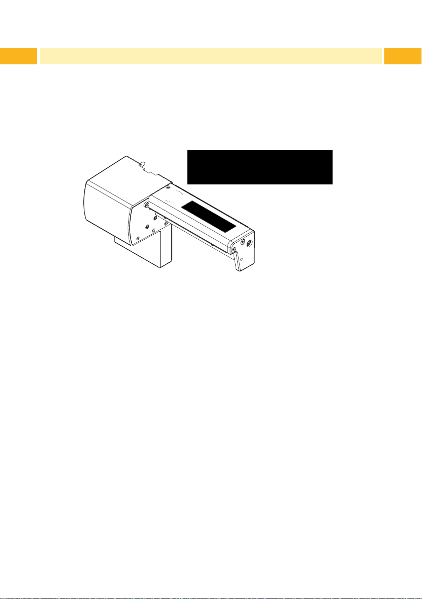
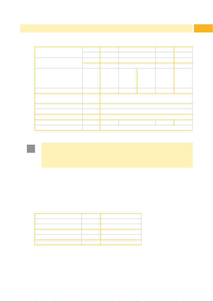
1.5 Technical Data
Standard cutter CU2 CU4 CU6 CU8
Cutter with peripheral
interface *
for printer type A2+ A4+ A4+M,
Material width max. mm 67 120 110 18 232
Material weight
cardboard
Material thickness mm 0,05 - 0,8
Cutting length mm > 5
Gap height mm 2,5
Cut frequency 1/min 130 120 110 100
Power supply peripheral connector of the printer
* Interface for trigger switch or external control
Attention!
The minimum cut length is depending on the media, in particular its
adhesive characteristics. Perform preliminary tests. Test the media
too,ifthemediaisveryhard,veryexibleorverythin.
5948382 5948000 5948001 5948002
CU2-I CU4-I CU6-I CU8-I
5948897 5948899 5948890 5948896
A4+T,
XD4T,
XC4
g/m² 60 - 500
A6+,
XC6
7
A8+
The cutters have a durability of more than 500,000 cuts. Depending on the
type of the cut material the blades could wear earlier and have to be replaced.
Used blades are not designed to be grinded again.
An optional Cutter Tray is available for the Cutters CU4 and CU4-I.
Cutter Tray 4 5946995
for printer type A4+
for cutter CU4, CU4-I
Material width max. mm 120
Cutting length max. mm 100
Stack height mm 36
Page 8
8 82 Mounting
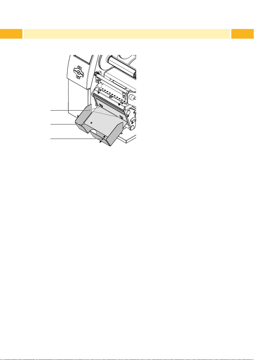
2.1 Mounting the Cutter Tray
1
2
3
1. Loosen the screws (1).
2. Place the cutter tray (2) on the screws (1) in front of the tear-off plate or
the dispense plate and slide it to the left until it stops.
3. Tighten the screws (1).
4. Adjust the length of the cutter tray (2) may by moving the slide (3).
Page 9

!
!
76
2 Mounting
2.2 Mounting the Cutter
Attention!
Disconnect the printer from the electrical outlet before
mounting or removing the cutter.
1
2
1. Loosen the screw (2).
2. Remove the front cover (1).
Attention!
For cutter operation with A+ printer there has to be mounted a
tear-off plate or a dispense plate on the printer, to lead the material
through the blades of the cutter.
4543
9
3. Insert the pins (3) of the cutter (7) into the holes (4) of the printer.
4. Press the cutter against the printer. That way the plug of the cutter will be
connected to the peripheral port (5) of the printer.
5. Secure the cutter (7) with the screw (6).
Page 10

10 10
i
i
3 PrinterConguration
Once the cutter is connected to the printer, the printer will automatically
recognize it on turn on.
The printer can be congured to suit the individual requirements of cut mode
in the „Setup“ menu. When the cutter is installed, the „Cutter“ menu will
appear.
Notice!
FordetailedinstructionsforcongurationCongurationManual
of the printer.
For setting the cutter parameters select
Setup
Parameter Meaning Default
Cutter
-> Machine param. -> Cutter .
Conguration of the cutter
> Cut
position
Notice!
The values of the setup are basic settings for the actual combination
printer/cutter. After changing the cutter or printer a re-adjustment
may be necessary.
Changes required for processing different print jobs should be
implemented additional offsets available in the software.
The offset values from setup and software are added together for
execution.
Offset of the cut position relative to the printed
image
Cut position with the initial offset value of "0"
causes to cut in the middle of the gap between
two labels.
If the cut position value is positive, the media
will be advanced before it is cut, that means
the distance between the cut edge and the
rear edge of the label increases.
0
Page 11

3 PrinterConguration
Under Setup -> Print parameters the method for recognizing
the material and the method of backfeed when using cut mode can be
selected.
Parameter Meaning Default
Label
sensor
Backfeed
Method for detecting the starting end of the
label.
Gap Sensor: Detection using changes in
the transparency between the label and
label gap.
Bottom-Reect: Detection using reex
marks on the bottom of the medium.
Continuos media: Synchronization of
the paper feed when using endless media
in cutting mode.
After loading media press the feed key.
That way a short feed and a synchronization cut are realized.
Method for backfeeding the material.
Backfeeding is necessary in the cutting
mode since the front edge of a second
section already passes the print line when
the rst label is moved to the cut position.
always: Backfeeding occurs independently
of print contents.
smart: Backfeeding only occurs when the
print contents of the next section is not
yet fully prepared when cutting the current
section. Otherwise, the second section is
pushed on and completed after removal of
the rst section without backfeeding.
Gap sensor
smart
11
Page 12

12 124 Loading Material
i
Load transfer ribbon and endless material as described in the Operator's
Manual of the printer
Use the tear-off mode information for loading endless material for cut
mode.
Place the media strip between the printhead and the drive roller, so that
the front edge of the strip reaches through the cutter.
5 Operation
5.1 Standard Operation
The printer is ready for operation when all connections have been made and
all materials are loaded correctly.
Notice!
To operate the cutter with continuous material in the printer
menu „Setup“ -> „Print parameters“ -> „Label sensor“ the setting
„Endless media“ has to be selected. Otherwise no synchronization
cut is carried out.
Switch on the printer.
The cutter performs a cut.
Press the feed key. For synchronization the media will be moved forward
and cut off.
Printers synchronization is not necessary when the printhead was not
opened between print jobs, even if the printer was powered off between
print jobs.
Activate the cut mode in the software.
For direct programming use the C-command ( Programming Manual).
Send a print job.
All labels in the job will be printed without stopping and be cut as chosen in
the software : after each label, after a specic quantity of labels, or at the
end of a print job.
Page 13

5.2 Operation Without Cover Plates
!
i
!
Due to the most varied materials it can come in rare cases to transportation
problems of the material depend of the cover plates.
It's possible to clear this problem with dismounting the cover plates.
Warning!
Risk of injury!
If the cover plates for a better performance should be removed,
appropriate compensating measures are to be arranged for the
guarantee of security!
Notice!
In case the material do adhere in follow of electrostatic charge it's
possible to use a discharge brush for the printer by cab.
2 21
135 Operation
3 4 4
Warning!
Risk of injury! The cutter blades are sharp!
Disconnect printer from electrical outlet .
1. Switch off the printer and demount the cutter.
2. Loosen screws (4) and detach cover plate (3).
3. Loosen screws (2) and detach cover plate (1).
Mounting in converse order.
Page 14

14 14
i
5 Operation
5.3 Operation with External Control
The CU-I cutters with peripheral interface additionally allow the mode "Cut on
Demand".
In this operating mode it is necessary to connect a trigger switch or an
external control to the peripheral interface on the cutter.
Notice!
This operating mode requires that there is a connection between
Pin 13 (STA) and Pin 12 (GND) at the peripheral interface ( chapter
"Peripheral Interface").
The printout of one label or a number of labels with the following cut will be
executed if
• a print job is available
• the previous cut has nished
• the trigger switch or the external control sends the START signal.
Page 15

6.1 Cleaning
!
!
Warning!
Disconnect the printer from the electrical outlet.
Attention!
Risk of injury. The cutter blades are sharp.
156 Maintenance
2 21
3 4 4
1. Remove the cutter from the printer.
2. Loosen the screws (2,4) and remove the cover sheets (1,3).
3. Remove dust and paper particles with a soft brush or a vacuum.
4. For cleaning the circular blade it is possible to turn the axle (6) with a
screwdriver for slotted head screws (slot width 7 mm). The rotation angle
of the circular blade is limited to 120°.
5. If it is necessary to turn the circular blade further, loosen the screw (5)
about 5 mm. Now the circular blade can be turned completely.
6. Remove all deposits at the cutter blades with isopropyl alcohol and a soft
cloth.
5
6
Page 16

16 166 Maintenance
i
Notice!
When cutting through the label material instead of the label gap
remains of adhesive may accumulate on the blades. If operating in
backfeed mode, such remains of adhesive may be deposited on the
drive roller as well.
Clean often the drive roller ( Printer Operator's Manual) and the
cutter blades.
7. Grease the cylindrical area (7) of the circular blade (8) with an All roundHigh quality Grease. For that hold a greased brush on the cylindrical area
and turn the axle (6) with a screwdriver for slotted head screws (slot width
7 mm).
During the turning the area is all-around greased.
8. If the screw (5) was loosened during cleaning, adjust the initial state of the
cutter chapter 6.3 .
9. Re-mount the cover sheet (1) using the screws M4x6 (2) and cover sheet
(3) using the screws M4x10 (4).
7 8 6
Page 17

6.2 Changing the Blades
!
321
4
i
!
Warning!
Disconnect the printer from the electrical outlet.
1. Remove the cutter from the printer.
2. Remove the cover sheets chapter 6.1.
3. Turn the axle (3) of the circular blade (2) with a screwdriver for slotted
head screws (slot width 7 mm) so that the inscription (1) of the blade
points downward. In this position the set screw (4) on the gear wheel can
be achieved from the rear of the cutter.
4. Loosen the set screw (4) a few turns.
176 Maintenance
Notice!
Save the washers (A, B, C) for the circular blade (2) and the
lineal blade (12) when dismounting the cutter.
Attention!
The springs (6, 15) are tense.
Always hold tight lineal blade (12) in its position and push its
axle slightly to the mounting plate (9) of the cutter.
4. Loosen the screws (8) and remove the bearing plate (15). The spring (13)
becomes slack.
5. Remove spring (13) from the lineal blade.
6. Pull the circular blade (2) out of the bearing (5). The spring (6) at the lineal
blade becomes slack.
If the lineal blade should not be changed skip to step 11.
Page 18

18 186 Maintenance
5 6 7 2 8
7. Remove spring (6) and lineal blade (12).
8. Insert the axle of the (new) lineal blade withe the washer (B) in the bearing
(10) of the mounting plate.
9. Hang in the slack spring (6) to the pins of the mounting plate (9) and the
lineal blade (11).
9 10 11 12 13 14 15
11
2
A
10. Turn the lineal blade (11) backwards. The spring (6) gets tense.
11. Insert the Axle of the (new) circular blade (2) with the washer (A) in the
bearing (5) of the mounting plate.
12. Place the washer (C) on the axle of the lineal blade.
13. Hang in the slack spring (13) to the pins (12,14) of the lineal blade and the
bearing plate.
14. Push the bearing plate (15) onto the blade axles (2, 11). The spring (13)
gets tense.
15. Append the bearing plate (15) to the prole (7) using the screws (8).
16. Attend on an accurate position of the bearing plate (15) to the prole (7) of
the cutter and tighten the screws (8).
17. Tighten the set screw (4) at the gear wheel.
18. Lubricate the circular blade chapter 6.1 and adjust its initial state
chapter 6.3.
19. Re-mount the cover sheets chapter 6.1.
B C
Page 19

6.3 Setting the Initial State of the Cutter
21 3 4 5
To operate the cutter correctly after cleaning or after changing the blades the
circular blade (4) and the clock wheel (11) must be adjusted to each other.
6
6
1. Unscrew the screws (1), (3) and (6, at the rear).
2. Remove the cover (2).
7 8
196 Maintenance
3. Turn the axle (5) of the circular blade with a screwdriver for slotted head
screws (slot width 7 mm) so that the planar area (8) of the blade axle
becomes parallel to the base plate (7).
Page 20

20 20
6 Maintenance
109 11 109 109
1 - right 2 - wrong 3 - wrong
4. Check the position of the clock wheel (11).
• If the clock wheel is in the right position 1, the edge (10) of the clock wheel
(11) is located in the area of the marking (9).
• If the clock wheel is in position 2 or 3 turn the circular blade to reach the
position 1 :
12
• Loosen screw (12) about 5 mm.
• Turn the circular blade by one or two full turns, until the planar area
(8) of the blade axle becomes parallel to the base plate (7) again
and the clock wheel reaches the position 1
• Tighten screw (12).
5. Mount the cover.
Page 21

7.1 Pin Assignment
i
For use in a network environment or with a switch, the CU-I cutters are
equipped with a peripheral interface to allow control of the cutting process.
The interface has a 15 pin SUB-D connector (1).
217 Peripheral Interface
Pin 15
Pin 9
Pin Signal Direction System Function User function
1 XSTART Input Start signal
2 XFEH Input External error
3 - 4 - Output - Control bit 3
5 XEDG Output No existing print job Control bit 1
6 XDNB Output Printer is not ready Control bit 2
7 XEGES Output Print of a label has started Control bit 0
8 GND (Output) Ground (0V)
9 RX-
START
10 RXFEH (Input) External error (reverse line)
11 - 12 GND (Output) Ground (0V)
13 STA Input Start signal is active
14 RUEL Output Reverse line
15 24P (Output) Operating voltage +24V,
(Input) Start signal (reverse line)
Pin 8
Pin 1
(for all output signals)
100mA
Notice!
The description of the system functions is included in this manual.
For more information about the user functions Programming
Manual, Commands x and X.
Page 22

22 227 Peripheral Interface
7.2 Explanation of the Signals
Pin Signal Description Activation /
Active State
1 XSTART
2 XFEH
3 - 4 - 5 XEDG
6 XDNB
7 XEDST
8 GND
Start signal
triggers the start of the print when using the
“Cut on demand“ operating mode,
This signal is checked if there is a connection between signal STA and ground GND.
External error
An error has occurred in an externally controlled device.
The label print is stopped and the display
of the printer shows the message "External
error".
After the error is corrected, it is possible to
press the pause key and the print job will
continue. The last label printed before the
error occurred will be repeated. Pressing
the cancel key will stop the print job and the
printer will be reset.
No existing print job
There is no print job currently available.
Printer is not ready
An error has occurred on the printer.
The label print is stopped and the details
and type of error can be read from the
printer display ('Ribbon out'; 'Paper out'; 'No
label')
Print of label has started
The printing of a label is indicated with a
20 ms pulse.
Ground ( 0 V )
Switch on +24 V
between Pin 1
and Pin 9
Switch on +24 V
between Pin 2
and Pin 10
Contact between
Pin 5 and Pin 14
is open
Contact between
Pin 6 and Pin 14
is open
Contact between
Pin 7 and Pin 14
is open
9 RX-
START
10 RXFEH
11 - -
Start signal (reverse line)
External error (reverse line)
Page 23

7 Peripheral Interface
Pin Signal Description Activation /
Active State
12 GND
Ground ( 0 V )
23
13 STA
14 RUEL
15 24P
Start signal is active
The signal enables the "Cut on demand"
operating mode.
In this case the XSTART signal is checked.
With signal STA disabled the cutter is operated in the standard mode.
Reverse line foe all output signals
Operating voltage +24 V, 100 mA
CAUTION ! Output !!!
DO NOT connect any external voltage
at Pin 15 !
Connect Pin
13 with Pin 12
(GND)
7.3 Circuit Diagram of Inputs
The XSTART and XFEH inputs are optocouplers with a current limiting resistor
of 2.2kΩ giving a voltage of 24V in the input circuit.
For each signal X[IN] there is a separate reverse line X[IN]R via the plug
connector. From that, the following matching pairs of signals result :
Pin 1 - XSTART
Pin 9 - RXSTART
Pin 2 - XFEH
Pin 10 - RXFEH
The input signal STA (PIN 13) is connected to GND (PIN 12) for the "Cut on
Demand" operating mode.
For external control of cut mode, the connecting device (trigger switch,
external control) must be equipped with a 15 pin SUB-D connector.
Page 24

24 24
7 Peripheral Interface
Example circuit diagram for a trigger switch :
XSTART 1
XFEH 2
3
4
XEDG 5
XDNB 6
XEGES 7
GND 8
RXSTART 9
RXFEH 10
11
GND 12
STA 13
RUEL 14
24P 15
7.4 Circuit Diagram of Outputs
All outputs are established through solid-state relays. The outputs are
connected to one another on one-side. The common line leads to the plug
connector as a RUEL signal.
The switch function of the outputs is to open or close the contact between the
joint line RUEL and the respective output.
Electrical requirements : U
Pin 4 - not used
Pin 5 - XEDG
Pin 6 - XDNB
Pin 7 - XEGES
Pin 14 - RUEL
= 42 V , I
max
= 100 mA
max
Page 25

8.1 Reference to the EU Declaration of Conformity
The cutters of the CU series comply with the relevant fundamental regulations
of the EU Rules for Safety and Health:
• Directive 2014/30/EU relating to electromagnetic compatibility
• Directive 2011/65/EU on the restriction of the use of certain hazardous
substances in electrical and electronic equipment
EU Declaration of Conformity
https://www.cab.de/media/pushle.cfm?le=2714
8.2 FCC
NOTE : This equipment has been tested and found to comply with the
limits for a Class A digital device, pursuant to Part 15 of the FCC Rules.
These limits are designed to provide reasonable protection against
harmful interference when the equipment is operated in a commercial
environment. The equipment generates, uses, and can radiate radio
frequency and, if not installed and used in accordance with the
instruction manual, may cause harmful interference to radio communications. Operation of this equipment in a residential area is likely to cause
harmful interference in which case the user may be required to correct
the interference at his own expense.
258 Licences
Page 26

26 26
This page was intentionally left blank.
 Loading...