

Page 1
USB SuperBooster
Wall Plate
User Manual
Page 2

Introduction
Thank you for purchasing the USB SuperBooster Wall Plate. Conquer USB length
limitations and put your USB devices where you need them with the patent pending USB
SuperBooster Wall Plate from Cables To Go. This wall plate solution extends the
distance of a USB device to a host computer up to 150ft so you can place your USB
projector, camera, printer, or any other USB device exactly where you want it! The USB
SuperBooster Wall Plate is powerful yet simple, with no drivers to install or special
software required. It is also compatible with any computer that supports USB.
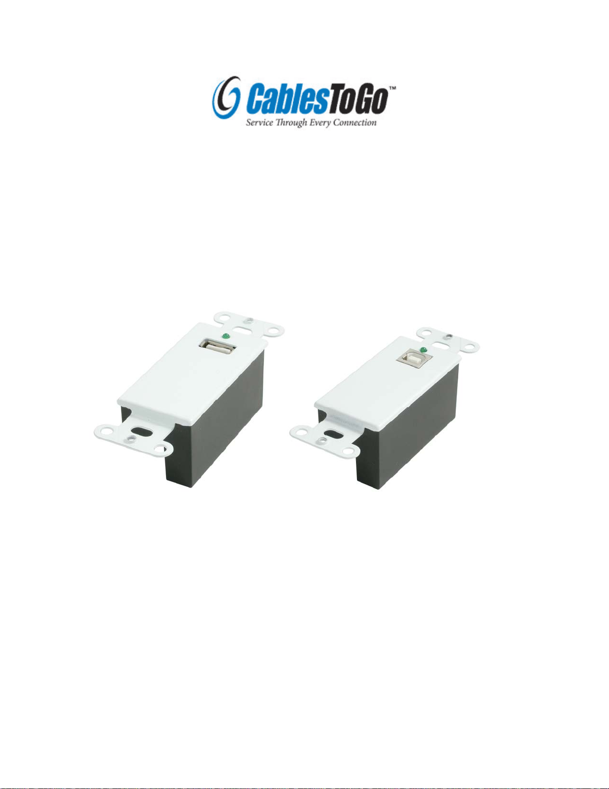
This plug-and-play device consists of a transmitter unit and receiver unit incorporated
into two, single gang Decora compatible wall plates. The transmitter/receiver pair is
connected via standard Cat5, Cat5E, or Cat6 UTP cable allowing for easy in-wall
installation. This makes for a clean, finished installation important for home owners,
classrooms, offices and anywhere you don’t want visible cables lying around. Use preterminated network cables or pull un-terminated cable and use the included tool-less IDC
RJ45 connectors. The USB SuperBooster Wall Plate is self-powered so no external
power source is required.
Features
• Extends the distance of a USB device from a USB-enabled computer up to 150ft
• Ideal for use with USB projectors, interactive whiteboards, cameras, printers,
web cams, hubs, or any other USB device
• Fits a standard J-box
• Compatible with Leviton Decora® brand cover plates
• Self-powered so no external power source is required
• Uses standard Cat5/Cat5E/Cat6 patch cord (not included) for ease of use and
flexibility
• Included tool-less IDC RJ45 connectors allow you to terminate your own cable
• Compliant with USB Specification 1.1
• Connectors:
o Transmitter: USB Type B Female; RJ45 Female
o Receiver: USB Type A Female; RJ45 Female
*Decora™ is a registered trademark of Leviton Manufacturing Company, Inc. This Product is not manufactured or endorsed by the
Leviton Manufacturing Company, Inc.
Package Contents
• USB SuperBooster Wall Plate- Transmitter Unit
• USB SuperBooster Wall Plate- Receiver Unit
• (2) Two RJ45 tool-less IDC connectors
• (4) Four #6x32 slotted/phillips screws
• User Guide
1
Page 3

Installing your USB SuperBooster Wall Plate
The USB SuperBooster Wall Plate has a transmitter unit and a receiver unit. Make
certain you install the transmitter unit at your computer or source side.
The receiver unit needs to be installed on the device side.
1) Install the Transmitter unit in a standard J-box where you want your
source/computer
2) Install the Receiver unit in a standard J-box where you want your USB device
3) Use a pre-terminated Cat5/Cat5E/Cat6 cable (recommended) or terminate your
own cable using the tool-less RJ45 connectors included to connect the two wall
plates together (see below for instructions on terminating your own cable)
4) Plug your computer into the source end (USB B side) using a standard A/B USB
cable (The green LED will light to indicate you have a good connection to the
wall plate)
5) Plug your device into the receiver end (USB A side) using a standard A/B (or
A/Mini-B) USB cable (The green LED will light to indicate you have a good
connection to the wall plate)
6) Turn your computer/source on and begin using your device
Terminating a Cat5/Cat5E/Cat6 Cable Using the Tool-less IDC
1) Open the plug by lifting the clear plastic end
2) Pin 1 of the connector is on the left side of the clear plastic shell while Pin 8 is on
the right side of the connector (with RJ45 connector facing away from you)
3) Thread the white/orange conductor on your Cat5/5E/6 cable into Pin 1
4) Thread the orange conductor on your Cat5/5E/6 cable into Pin 2
5) Thread the white/green conductor on your Cat5/5E/6 cable into Pin 3
6) Thread the blue conductor on your Cat5/5E/6 cable into Pin 4
7) Thread the white/blue conductor on your Cat5/5E/6 cable into Pin 5
8) Thread the green conductor on your Cat5/5E/6 cable into Pin 6
9) Thread the white/brown conductor on your Cat5/5E/6 cable into Pin 7
10) Thread the brown conductor on your Cat5/5E/6 cable into Pin 8
11) Repeat steps 1-10 to terminate the other end of your Cat5/5E/6 cable
Pin 1
2
Pin 8
Page 4

Termination Chart
Pin Number Network (Cat5/5E/6)
Conductor Color
1 white/orange
2 orange
3 White/green
4 Blue
5 White/blue
6 Green
7 White/brown
8 brown
Application Diagram
Transmitter Receiver
1501 Webster Street
Dayton, Ohio 45404
1-800-293-4970
www.cablestogo.com
3
 Loading...