

Page 1

USB 2.0 3.25” Interna l Hub- 4-Port
USER’S MANUAL
I.
Introduction
The Cables To Go USB 2.0 High-Speed Front-Bay Hub has 4 ports that will connect to either
USB 2.0 High-Speed or USB 1.1 peripheral d evices. The interna l USB hub can b e m ounted into
any 3.5 inch drive bay allowing for hassle free front-side connection of USB devices. With fo ur
downstream ports, it is designed to work with mice, keyboards, CD-R/RW's, hard drives,
webcams, flash card readers and other USB enabled devices. The USB 2.0 High-Speed
Front-Bay Hub can transfer data at 480 Megabits per second, making it 40 times faster than
previous USB adapters and 20% fast er than Fir eWire. The p lug and play desig n mak es for easy,
trouble-free installation of your USB devices.
II.
Features
• Compliant with Universal Serial Bus Specification Revision 2.0
• All downstream facing ports can handle high-speed (480Mbps), full-speed (12Mbps),
and low-speed (1.5Mbps) transaction
• Support Plug & Play and Hot Swappable capability
• Equipped with over-current Detection & Protection
• Connects up to 127 USB devices
Specification
III.
• Dimensions: 90*101*25mm (length*width*height)
• Gross weight: 240g
• Bus power mode only
• Root Hub with 4 downstream facing ports which are shared by OHCI & EHCI Host
Controller core
• 1 upstream port & 4 downstream ports
• Led status indicators
• Supports Windows 98/98 SE/Me/2000/XP/Vista/7 and Mac OS 8.6 or greater
1
Page 2
IV.
Package contents
• 3.25” panel frame main body * 1
• Screw * 4
• Bracket * 1
• USB AM – 4P HSG extension cable * 1
• Power supply cable * 1
•
Installation
We suggest that you read the steps in this manual carefully prior to installing to fully
understand the installation method for obtaining maximum efficiency.
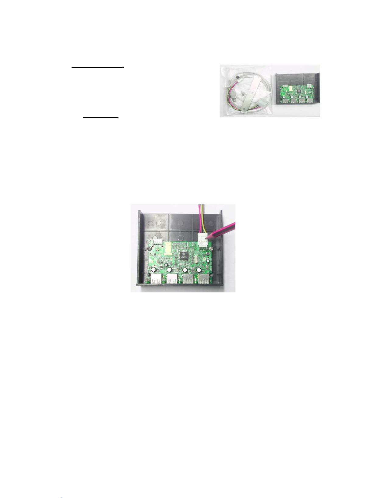
1 Connect the small 4-pin connector of the power supply cable to the right mating
connector on the circuit board of the hub main body. (This has been designed so that it can be
connected only in the proper way).
2
Page 3

2 Connect the small 4-pin connector of the USB cable to the mating one on the circuit
board of the hub main body (this has also been designed so that it can only be connected in the
proper way).
3 Put the hub into the available 3.25” drive bay on the computer chassis.
4 Connect the other end of the power supply cable to the power supply unit (PSU) in the
computer.
3
Page 4

5 Extend the USB connector of the USB cable through brack et hole at b ack of the P C and
then connect to the USB port on the PC.
6 Installation finished.
4
Page 5

VI.
Introduction of use
1 Start up the computer when above connection is properly finished.
2 Click My Computer on Desktop and open Properties.
3 Choose Hardware and then click Device Manager. The installation is complete when
Generic USB Hub is displayed under Universal Serial Bus Controllers.
5
Page 6

4 The corresponding LED will shine when a USB device is plugged into the USB port.
This shows the hub functions normally.
3555 Ketterin g Blvd
Moraine OH 45439
1-800-293-4970
www.cablestogo.com
6
 Loading...