

Page 1
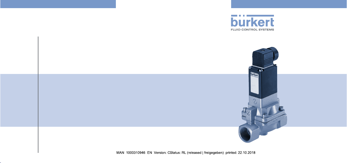
Type 5282
2/2-Way Solenoid Valve
2/2-Wege-Magnetventil
Électrovanne à 2/2 voies
Bedienungsanleitung
Manuel d‘utilisation
Operating Instructions
Page 2
Contents
english
1 Operating Instructions ....................................................................... 2
2 Authorized use .................................................................................. 3
3 Basic safety instructions .................................................................... 3
4 Technical data ................................................................................... 5
5 Installation ............................................................................................7
6 Maintenance, troubleshooting ......................................................... 11
7 Spare parts ..................................................................................... 12
8 Transport, Storage, Disposal ........................................................... 13
2
1 OPERATING INSTRUCTIONS
The operating instructions contain important information.
▶ Read the operating instructions carefully and follow the safety instruc-
tions in particular, and also observe the operating conditions.
▶ Operating instructions must be available to each user.
▶ The liability and warranty for the product / device are void if the operat-
ing instructions are not followed.
1.1 Symbols
▶ Designates an instruction to prevent risks.
→ designates a procedure which you must carry out.
Warning of injuries:
DANGER!
Imminent danger. Serious or fatal injuries.
WARNING!
Potential danger. Serious or fatal injuries.
CAUTION!
Danger. Minor or moderately severe injuries.
Warns of damage to property:
NOTE!
Page 3

2 AUTHORIZED USE
english
Non-authorized use of the solenoid valve type 5282 may be a
hazard to people, nearby equipment and the environment.
▶ The device is designed to control, shut o and meter neutral media
up to a viscosity of 21 mm
▶ Provided the cable plug is connected and installed correctly, e.g. Bürk-
ert type 2508, the device satises protection class IP65 in accordance
with DIN EN 60529 / IEC 60529.
▶ During use observe the authorized data, the operating conditions and
conditions of use specied in the contract documents, on the type
label and in the operating instructions, as described in the chapter
entitled “4 Technical data”.
▶ Correct transportation, correct storage and installation and careful
use and maintenance are essential for reliable and faultless operation.
▶ Use the device only as intended.
2.1 Denition of term
In these operating instructions, the term “device” always refers to the
Type 5282.
2
/s.
3 BASIC SAFETY INSTRUCTIONS
These safety instructions do not make allowance for any
• contingencies and events which may arise during the installation,
operation and maintenance of the devices.
• local safety regulations - the operator is responsible for observing
these regulations, also with reference to the installation personnel.
Danger - high pressure.
▶ Before loosening the pipes and valves, turn o the pressure and
vent the pipes.
Risk of electric shock.
▶ Before reaching into the device or the equipment, switch o the
power supply and secure to prevent reactivation.
▶ Observe applicable accident prevention and safety regulations for
electrical equipment.
Risk of burns/risk of re if used for a prolonged switch-on time
through hot device surface.
▶ Keep the device away from highly ammable substances and media
and do not touch with bare hands.
3
Page 4
Risk of injury due to malfunction of valves with alternating current
english
(AC).
Sticking core causes coil to overheat, resulting in a malfunction.
▶ Monitor process to ensure function is in perfect working order.
Risk of short-circuit/escape of media through leaking screw joints.
▶ Ensure seals are seated correctly.
▶ Carefully screw valve and connection lines together.
General hazardous situations.
To prevent injury, ensure that:
▶ The device may only be used in the explosion-protected area if an
appropriate additional identication is attached to the type label.
For use observe the additional information enclosed with the device
together with safety instructions for the explosion risk area.
▶ The enclosed UL instructions must be followed in the UL area.
▶ Do not put any loads on the body (e.g. by placing objects on it or
standing on it).
▶ Do not make any external modications to the device bodies. Do
not paint the body parts or screws.
4
▶ The system cannot be activated unintentionally.
▶ Installation and repair work may be carried out by authorized techni-
cians only and with the appropriate tools.
▶ After an interruption in the power supply or uid supply, ensure that
the process is restarted in a dened or controlled manner.
▶ The device may be operated only when in perfect condition and in
consideration of the operating instructions.
Type 5282 was developed with due consideration given to
accepted safety rules and is state-of-the-art. Nevertheless, dangerous situations may occur.
3.1 Warranty
The warranty is only valid if the device is used as intended in accordance
with the specied application conditions.
3.2 Information on the internet
The operating instructions and data sheets for type 5282 can be found
on the internet at:
www.buerkert.com
Type 5282
Page 5
4 TECHNICAL DATA
english
4.1 Operating conditions
The following values* are indicated on the type label:
• Voltage (tolerance ± 10 %) / current type
• Coil power consumption
(active power in W - at operating temperature)
• Pressure range
• Body material brass (MS) or stainless steel (VA)
• Seal material FKM, EPDM, NBR
* see description of type label below
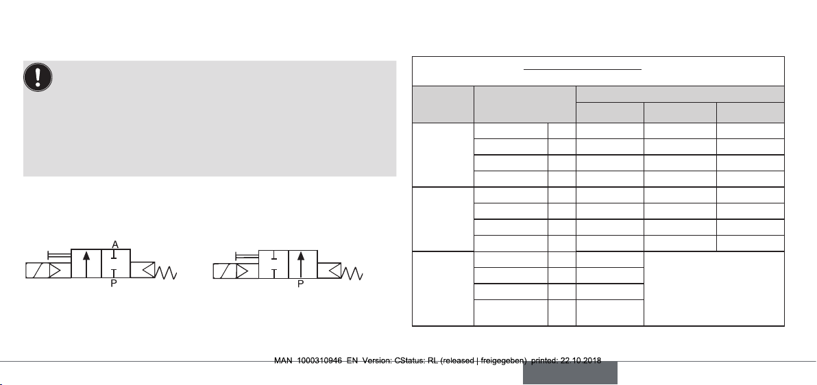
Operating principle 2/2-way valve:
A (NC) B (NO)
2 ( )
1 ( )
Type of protection: IP65 in accordance with DIN EN 60529 / IEC 60529
with correctly connected and installed device socket,
e.g. Bürkert Type 2508
2 (B)
1 ( )
4.2 Application conditions
Ambient temperature: max. +55 °C
The following values must also be observed for valves with UL/UR
approval:
Fluid Temperature
Dry air,
inert gas
Water Fluid [°F] +41...+194 +41...+176 +41...+194
Hazardous
uid:
oil, LPG
gas,
oxygen
Fluid [°F] +32...+194 +32...+176 -13...+194
Ambient [°F] +32...+131 +32...+131 -13...+131
Fluid [°C] 0...+90 0...+80 -25...+90
Ambient [°C] 0...+55 0...+55 -25...+55
Ambient [°F] +41...+131 +41...+131 +41...+131
Fluid [°C] +5...+90 +5...+80 +5...+90
Ambient [°C] +5...+55 +5...+55 +5...+55
Fluid [°F] +32...+194
Ambient [°F] +32...+131
Fluid [°C] 0...+90
Ambient [°C] 0...+55
FKM NBR EPDM
Seal materials
5
Page 6

Permitted medium temperature and permitted media depending on seal
5282 A 25 EPDM MS
00134469
english
material:
Seal
material
Medium
temperature
Permitted media
FKM 0 °C ... +90 °C Per-solutions, hot oils without additives,
diesel and heating oil without additives,
detergent solution
EPDM -25 °C ... +90 °C Oil and grease-free liquids,
cold and hot water
NBR 0 °C ... +80 °C Cold and warm water
Operating duration
Unless otherwise indicated on the type label, the solenoid system is suitable
for continuous operation.
Important information for functional reliability during continuous operation: If standstill for a long period at least 1-2 acti-
vations per day are recommended.
Service life
High switching frequency and high pressures reduce the service life.
6
4.3 Conformity
Type 5282 conforms with the EU Directives according to the EU Declaration of Conformity.
4.4 Standards
The applied standards, which verify conformity with the EU Directives,
can be found on the EU-Type Examination Certicate and / or the EU
Declaration of Conformity.
4.5 Type label
W17 LU
Orice
Seal material
Body material
Connection thread,
pressure range
Voltage, frequency,
power consumption
Manufacturer-Code
Example:
Operating prinziple
Type
Type label
Id. Number
Fig. 1: Location and inscription of the type label
G1 1/4 P
N 0,2 - 16 bar
230V 50-60Hz 8W
Made in Germany
Page 7
5 INSTALLATION
english
5.1 Safety instructions
DANGER!
Risk of injury from high pressure in the equipment.
▶ Before loosening the pipes and valves, turn o the pressure and
vent the pipes.
Risk of injury due to electrical shock.
▶ Before reaching into the device or the equipment, switch o the
power supply and secure to prevent reactivation.
▶ Observe applicable accident prevention and safety regulations for
electrical equipment.
WARNING!
Risk of injury from improper installation.
▶ Installation may be carried out by authorized technicians only and
with the appropriate tools.
Risk of injury from unintentional activation of the system and an
uncontrolled restart.
▶ Secure system from unintentional activation.
▶ Following assembly, ensure a controlled restart.
5.2 Before installation
Installation position:
Installation can be in any position.
Preferably: Actuator upright.
→ Prior to installation check pipelines for dirt and, if required, clean.
Dirt lter: To ensure that the solenoid valve functions reliably, a dirt filter (≤ 500 µm) must be
installed in front of the valve inlet.
5.3 Installation
→ Hold the device with a suitable tool (open-end wrench) on the body
and screw into the pipeline.
NOTE!
Caution risk of breakage.
• Do not use the coil as a lever arm.
→ Observe direction of ow:
The arrow on the body indicates the direction of ow (no function in
opposite ow direction).
7
Page 8

5.4 Manual emergency actuation
english
NOTE!
Caution!
• When the manual emergency actuation is locked, the valve can no
longer be actuated electrically.
Manual emergency
Fig. 2: Manual emergency actuation
8
Press
Turn
actuation
1
2
5.5 Changing valve function
(not possible for var Code CF02 and MT50)
max. 2.0 Nm
Pilot valve
O-rings
Identication for
the ow direction
Fig. 3: Installing the pilot valve (changing valve function)
DANGER!
Discharge of medium due to leaking device.
If the O-rings are forgotten or incorrectly inserted during installation
of the pilot valve, the device will be damaged and medium will be
discharged.
▶ Before screwing in the pilot valve, correctly insert O-rings into the
depressions.
Page 9

Function NC
english
The pilot valve is
installed in such a
way that the manual
emergency actuation
points in the direction
opposite to the
direction of ow
arrow.
Fig. 4: Valve functions (NC/NO)
Function NC Function NO
Flow direction
Function NO
The pilot valve is
installed in such a
way that the manual
emergency actuation
points in the same
direction as the iden-
tication for the ow
direction.
5.6 Setting the switching times
The closing and opening times of the valve can be changed if required
with the side throttle screws.
CAUTION!
Discharge of medium if the throttle screws are unscrewed too far.
Extending
closing times
Fig. 5: Extending / reducing switching times
Extending
opening times
Reducing
closing times
Reducing
opening times
NOTE!
Pressure surges caused by liquid media and short closing times.
• If closing times are fairly short, liquid media cause higher pressure
surges. These may reduce the service life of the diaphragm and
destroy other devices and components in the system.
Shorten closing
times
Fig. 6: Shorten closing times for DN13 stainless steel
9
Page 10

5.7 Electrical connection of the cable plug
english
DANGER!
Note the voltage and current type as specied on the type label.
Risk of injury due to electrical shock.
▶ Before reaching into the device / equipment switch o the power
supply and secure to prevent reactivation.
▶ Observe applicable accident prevention and safety regulations for
electrical equipment.
If the protective conductor is not connected, there is a risk of electric
shock.
▶ Always connect protective conductor and check electrical continu-
ity coil and body.
max. 1 Nm
Seal
Authorized cable plug e.g.
Type 2508 or other suitable cable
Fig. 7: Electrical connection of the cable plug
10
plug in accordance with
DIN EN 175301-803 Form A
→ Tighten cable plug (for permitted types see data sheet), observing
max. torque 1 Nm.
→ Check that seal is tted correctly.
→ Connect protective conductor and check electrical continuity between
coil and body.
5.7.1 Electrical connection - Pulse (CF 02)
24 3
(=) ∼
(+) L1
(–) N
1
Fig. 8: Circuit diagram
PE
The connection terminals in the device socket are identied with
the numbers 1 to 3 according to the terminals on the valve.
Terminal 1
Terminal 2
Terminal 3
Earth connector
Page 11

Procedure:
english
→ Pulse valves (variable code CF 02) as in “Fig. 8: Circuit diagram”
connect. Pulse to Terminal 1 closes the valve; pulse to Terminal 2
opens the valve.
→ Connect standard version L1/+ or N/– to Terminals 1 and 2 irre-
spective of the polarity.
NOTE!
Important information:
▶ Avoid emitting pulses simultaneously to both coil windings.
▶ Do not switch any other consumers (relays, etc.) at the same time
as the terminals.
▶ The coil connection, to which voltage is not applied, must be gal-
vanically isolated (open).
▶ If two or more valves are switched in parallel, ensure that this
requirement is met by using 2-pole or multi-pole switches.
Electrical connection of the position indicator (var code LF02 or
LF03) see operating instructions Type 1060.
6 MAINTENANCE, TROUBLESHOOTING
6.1 Safety instructions
DANGER!
Risk of injury from high pressure in the equipment.
▶ Before loosening the pipes and valves, turn o the pressure and
vent the pipes.
Risk of injury due to electrical shock.
▶ Before reaching into the device or the equipment, switch o the
power supply and secure to prevent reactivation.
▶ Observe applicable accident prevention and safety regulations for
electrical equipment.
WARNING!
Risk of injury from improper maintenance.
▶ Maintenance may be carried out by authorized technicians only and
with the appropriate tools.
Risk of injury from unintentional activation of the system and an
uncontrolled restart.
▶ Secure system from unintentional activation.
▶ Following maintenance, ensure a controlled restart.
11
Page 12

6.2 Malfunctions
english
If malfunctions occur, check whether:
→ the device has been installed according to the instructions,
→ the electrical and uid connections are correct,
→ the device is not damaged,
→ all screws have been tightened,
→ the voltage and pressure have been switched on,
→ the pipelines are clean.
Malfunction Possible cause
Valve does
not switch
Valve does
not close
NOTE!
Explosion protection versions may only be repaired by the
manufacturer.
12
Short-circuit or coil interrupted
Medium pressure outside the permitted pressure range
Manual emergency actuation locked
Internal space of the valve is dirty
Manual emergency actuation locked
7 SPARE PARTS
CAUTION!
Risk of injury and/or damage by the use of incorrect parts!
Incorrect accessories and unsuitable spare parts may cause injuries
and damage the device and the surrounding area.
▶ Use original accessories and original spare parts from Bürkert only.
7.1 Ordering spare parts
Replacement part sets
Order the spare-part set SET 3 or the pilot control with solenoid coil (com-
plete) by quoting the identication number of the device.
• See replacement part sets “7.2 Exploded drawing”.
• The identication number of the device can be found on the type label.
See also chapter “4.5 Type label”.
Page 13

7.2 Exploded drawing
english
Pilot valve
SET 3
8 TRANSPORT, STORAGE, DISPOSAL
NOTE!
Transport damages.
Inadequately protected equipment may be damaged during transport.
• During transportation protect the device against wet and dirt in
shock-resistant packaging.
• Avoid exceeding or dropping below the allowable storage
temperature.
Incorrect storage may damage the device.
• Store the device in a dry and dust-free location!
• Storage temperature: -40 °C ... +80 °C
Damage to the environment caused by device components
contaminated with media.
▶ Observe applicable regulations on disposal and the environment.
▶ Observe national waste disposal regulations.
→ Dispose of the device and packaging in an environmentally friendly
manner.
13
Page 14

www.burkert.com
Bürkert Fluid Control Systems
Sales Center
Christian-Bürkert-Str. 13-17
D-74653 Ingelfingen
Tel. + 49 (0) 7940 - 10 91 111
Fax + 49 (0) 7940 - 10 91 448
E-mail: info@burkert.com
International address
www.burkert.com
Manuals and data sheets on the Internet: www.burkert.com
Bedienungsanleitungen und Datenblätter im Internet: www.buerkert.de
Instructions de service et fiches techniques sur Internet : www.buerkert.fr
© Bürker t Werke GmbH & Co. KG, 2015 - 2018
Operating Instructions 1810/23_EU-ML_00803322 / Original DE
 Loading...