

Page 1
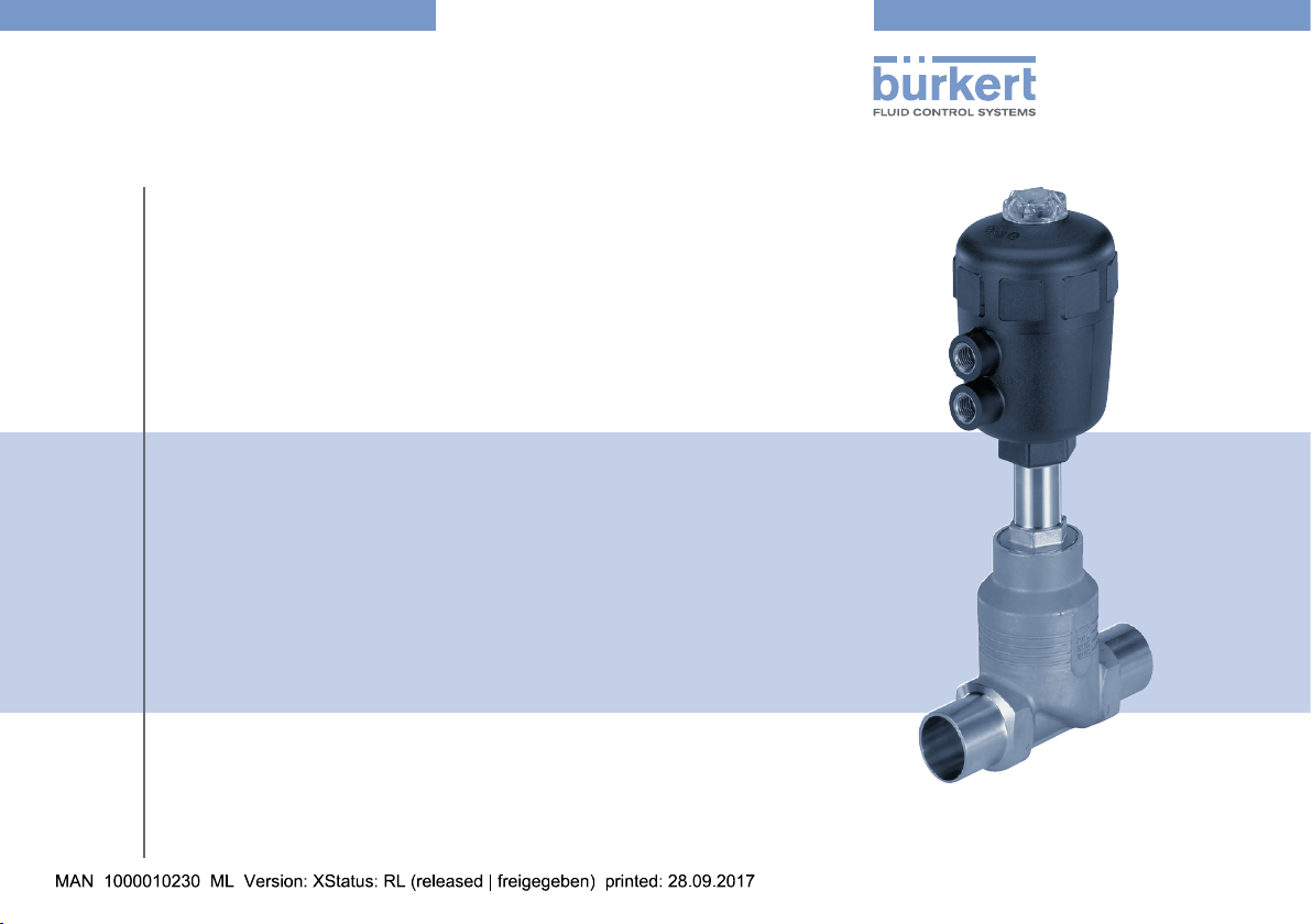
Type 2012
Globe control valve, pneumatically operated
Actuator sizes 40 mm - 125 mm, Nominal diameter DN10 - 65
Kolbengesteuertes Geradsitzventil
Antriebsgrößen 40 mm - 125 mm, Nennweiten DN10 - 65
Vanne à siège droit commandée par piston
Tailles d'actionneur 40 mm - 125 mm, Diamètre nominal DN10 - 65
Operating Instructions
Bedienungsanleitung
Manuel d‘utilisation
Page 2

We reserve the right to make technical changes without notice.
Technische Änderungen vorbehalten.
Sous réserve de modifications techniques.
© 2000 - 2017, Bürkert Werke GmbH & Co. KG
Operating Instructions 1709/21_EU-ML_00804072 / Original DE
Page 3

Type 2012
Contents
1 OPERATING INSTRUCTIONS ................................................................4
1.1 Symbols ....................................................................................... 4
1.2 Definition of term .......................................................................4
2 AUTHORIZED USE ......................................................................................5
3 BASIC SAFETY INSTRUCTIONS ..........................................................5
4 GENERAL INFORMATION ........................................................................6
4.1 Contact address ........................................................................6
4.2 Warranty ...................................................................................... 6
4.3 Information on the Internet ......................................................6
5 PRODUCT DESCRIPTION ........................................................................7
5.1 General description ..................................................................7
6 STRUCTURE AND FUNCTION...............................................................7
6.1 Structure ...................................................................................... 7
6.2 Function ....................................................................................... 8
7 TECHNICAL DATA ........................................................................................9
7.1 Conformity ................................................................................... 9
7.2 Standards .................................................................................... 9
7.3 Type label ....................................................................................9
7.4 Operating conditions ..............................................................10
7.5 Control functions .....................................................................14
7.6 Mechanical data.......................................................................14
8 INSTALLATION
8.1 Safety instructions ...................................................................15
8.2 Before installation ....................................................................15
8.3 Installation .................................................................................16
8.4 Pneumatic connection ............................................................18
8.5 Removal .....................................................................................18
9 MAINTENANCE, CLEANING ................................................................19
9.1 Safety instructions ...................................................................19
9.2 Maintenance work ...................................................................19
9.3 Replacing the valve seat ........................................................20
10 MALFUNCTIONS ........................................................................................21
11 REPLACEMENT PARTS .......................................................................... 22
11.1 Replacement part sets ...........................................................22
11.2 Overview of spare parts .........................................................22
12 TRANSPORT, STORAGE, DISPOSAL .............................................. 23
............................................................................................ 15
english
3
Page 4
Type 2012
Operating Instructions
1 OPERATING INSTRUCTIONS
The operating instructions describes the entire life cycle of the device.
Keep these instructions in a location which is easily accessible to
every user, and make these instructions available to every new owner
of the device.
WARNING!
The operating instructions contain important safety information!
Failure to observe these instructions may result in hazardous
situations.
▶ The operating instructions must be read and understood.
1.1 Symbols
DANGER!
Warns of an immediate danger!
▶ Failure to observe the warning may result in a fatal or serious
injury.
WARNING!
Warns of a potentially dangerous situation!
▶ Failure to observe the warning may result in serious injuries or
death.
CAUTION!
Warns of a possible danger!
▶ Failure to observe this warning may result in a moderate or
minor injury.
NOTE!
Warns of damage to property!
▶ Failure to observe the warning may result in damage to the
device or the equipment.
Indicates important additional information, tips and
recommendations.
Refers to information in these operating instructions or in
other documentation.
▶ Designates an instruction to prevent risks.
→ Designates a procedure which you must carry out.
1.2 Definition of term
The term “device” used in these instructions always stands for the
globe control valve Type 2012.
4
english
Page 5
Type 2012
Authorized Use
2 AUTHORIZED USE
Non-authorized use of the globe control valve Type 2012 may
be a hazard to people, nearby equipment and the environment.
▶ The device is designed for the controlled flow of liquid and gas-
eous media.
▶ In the potentially explosion-risk area the device may be used only
according to the specification on the separate Ex type label. For
use observe the additional information enclosed with the device
together with safety instructions for the explosion-risk area.
▶ Devices without a separate Ex type label may not be used in a
potentially explosive area.
▶ The admissible data, the operating conditions and conditions of
use specified in the contract documents, operating instructions
and on the type label are to be observed during use. These are
described in the chapter entitled “Technical Data”.
▶ The device may be used only in conjunction with third-party devices
and components recommended and authorized by Bürkert.
▶ Correct transportation, correct storage and installation and care-
ful use and maintenance are essential for reliable and faultless
operation.
▶ Use the device only as intended.
3 BASIC SAFETY INSTRUCTIONS
These safety instructions do not make allowance for any
• contingencies and events which may arise during the installation,
operation and maintenance of the devices.
• local safety regulations, whereby the operator is responsible for their
compliance, by the installation personnel too.
Danger – high pressure.
▶ Before dismounting the lines and valves, turn off the pressure and
vent the lines.
Risk of electric shock.
▶ Before reaching into the device, switch off the power supply and
secure to prevent reactivation.
▶ Observe applicable accident prevention and safety regulations
for electrical equipment.
Risk of injury when opening the actuator.
The actuator contains a tensioned spring. If the actuator is opened,
there is a risk of injury from the spring jumping out!
▶ The actuator must not be opened.
Risk of injury from moving parts in the device.
▶ Do not reach into openings.
english
5
Page 6
Type 2012
General Information
Risk of burns.
The surface of the device may become hot during long-term
operation.
▶ Do not touch the device with bare hands.
General hazardous situations.
To prevent injury, ensure:
▶ That the system cannot be activated unintentionally.
▶ Installation and repair work may be carried out by authorized
technicians only and with the appropriate tools.
▶ After an interruption in the power supply or pneumatic supply,
ensure that the process is restarted in a defined or controlled
manner.
▶ The device may be operated only when in perfect condition and
in consideration of the operating instructions.
▶ The general rules of technology apply to application planning and
operation of the device.
To prevent damage to property of the device, ensure:
▶ Supply the media connections only with those media which are
specified as flow media in the chapter entitled “7 Technical Data”.
▶ Do not put any loads on the valve (e.g. by placing objects on it
or standing on it).
▶ Do not make any external modifications to the valves.
▶ Do not paint the body parts or screws.
4 GENERAL INFORMATION
4.1 Contact address
Germany
Bürkert Fluid Control Systems
Sales Center
Christian-Bürkert-Str. 13-17
D-74653 Ingelfingen
Tel. + 49 (0) 7940 - 10 91 111
Fax + 49 (0) 7940 - 10 91 448
E-mail: info@de.buerkert.com
International
Contact addresses are found on the final pages of the printed operating manual.
You can also find information on the Internet under:
www.burkert.com
4.2 Warranty
The warranty is only valid if the device is used as authorized in accordance with the specified application conditions.
4.3 Information on the Internet
The operating instructions and data sheets for Type 2012 can be found
on the Internet at: www.burkert.com
6
english
Page 7
Type 2012
Product Description
5 PRODUCT DESCRIPTION
5.1 General description
The 2/2-way globe control valve Type 2012 is suitable for liquid and
gaseous media. It uses neutral gases or air (control media) to control
the flow of water, alcohol, oil, fuel, hydraulic fluid, saline solution, lye,
organic solvent and steam (flow media).
A particular feature of the globe control valves are screwed in seats
which can be changed if required.
5.1.1 Restrictions
WARNING!
Risk of injury from water hammer!
A water hammer could crack the lines and device. Due to the risk
of water hammer, valves with a flow direction above seat must
not be used for liquid media.
▶ Consider the type of flow direction and the type of medium for
operation of the device.
6 STRUCTURE AND FUNCTION
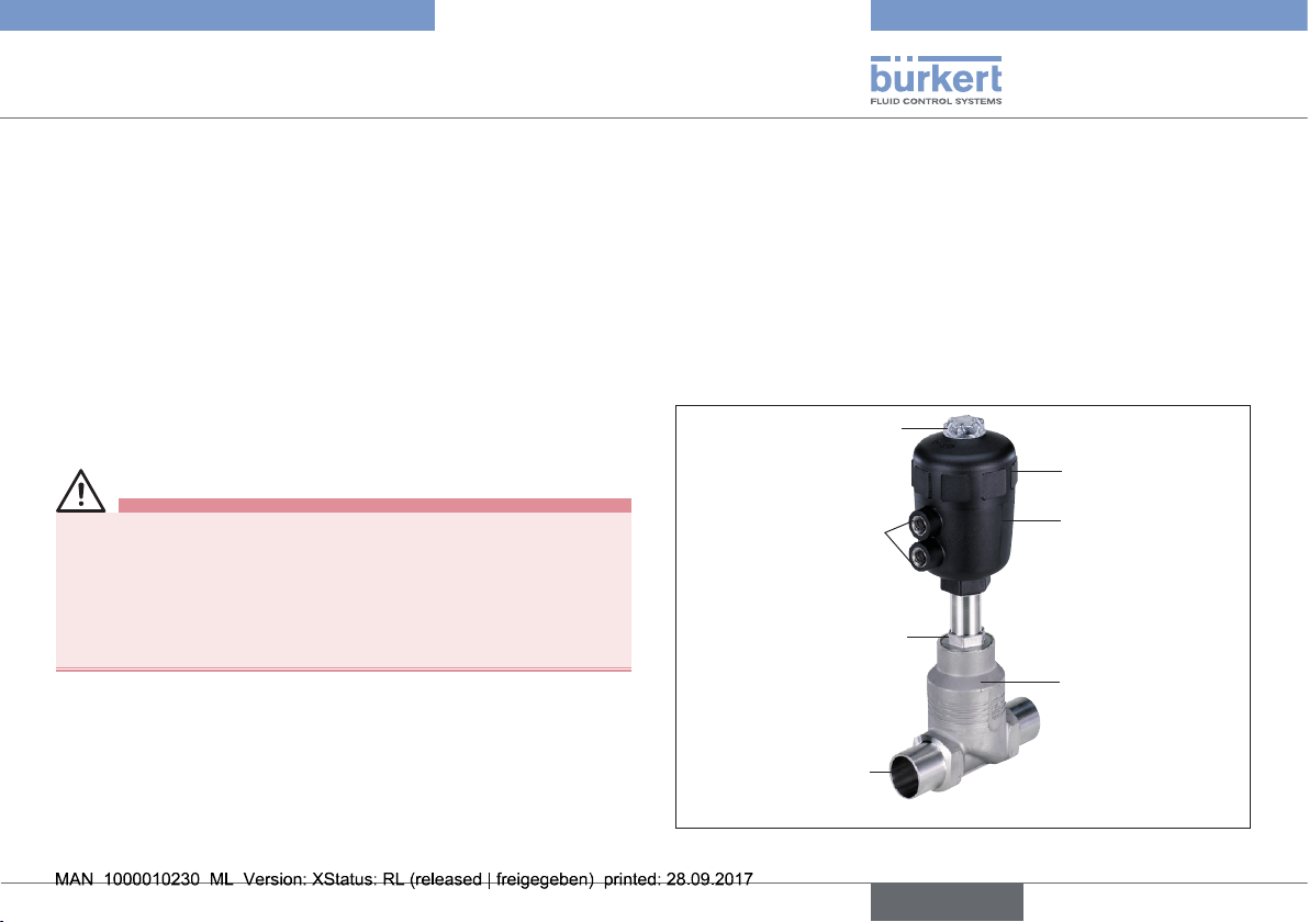
6.1 Structure
The globe control valve consists of a pneumatically actuated piston
actuator and a 2-way globe control valve body.
The actuator is manufactured from PA or, for special operating conditions, from PPS. The self-adjusting packing gland ensures a high
degree of tightness. The valve body, made of stainless steel, enables
high flow values.
Transparent cap with
position indicator
Pilot air ports
Interface actuator /
body with flats
Port connection
Actuator cover
Actuator body
Globe valve body
Fig. 1: Globe control valve Type 2012, Structure and description
english
7
Page 8
Type 2012
P
A
P
A
Structure and Function
6.2 Function
Depending on the version, the seat of the valve is closed with or against
the medium flow.
Spring force (CFA) or pneumatic pilot pressure (CFB and CFI) generates the closing force on the swivel plate. The force is transferred
via a spindle which is connected to the actuator piston.
6.2.1 Control functions (CF)
WARNING!
For control function I – Danger if pilot pressure fails.
For control function I control and resetting occur pneumatically. If
the pressure fails, no defined position is reached.
▶ To ensure a controlled restart, first pressurise the device with pilot
pressure, then switch on the medium.
A
(CFA)
B
(CFB)
B
P
Normally closed by spring action
Normally open by spring action
6.2.2 Flow direction below seat
Depending on the version, the valve is closed against the medium
flow with spring force (control function A, CFA) or with pilot pressure
(control function B or I, CFB or CFI).
As the medium pressure is under the swivel plate, this pressure
contributes to the opening of the valve.
WARNING!
Medium may be discharged if minimum pilot pressure is too
low or medium pressure too high.
If the minimum pilot pressure is too low for CFB and CFI or the
permitted medium pressure is exceeded, leaks may occur.
▶ Observe minimum pilot pressure.
▶ Do not exceed medium pressure.
▶ See chapter entitled “7.4.2 Pressure ranges”.
CFA CFB /
CFI
8
I
(CFI)
Actuating function via reciprocal
pressurisation
english
Fig. 2: Flow direction below seat (closing against medium)
Page 9

Type 2012
2012 A 32,0 PTFE VA
00182076
W1X LU
G 1/4 P med 15 bar
Pilot 5 - 10 bar
med 15 bar
Flow 1 ← 2
2012 A 40,0 PTFE VA
med 15 bar
Flow 1 ← 2
2012 A 40,0 PTFE VA
FLNSCH Pmed 10bar
Technical Data
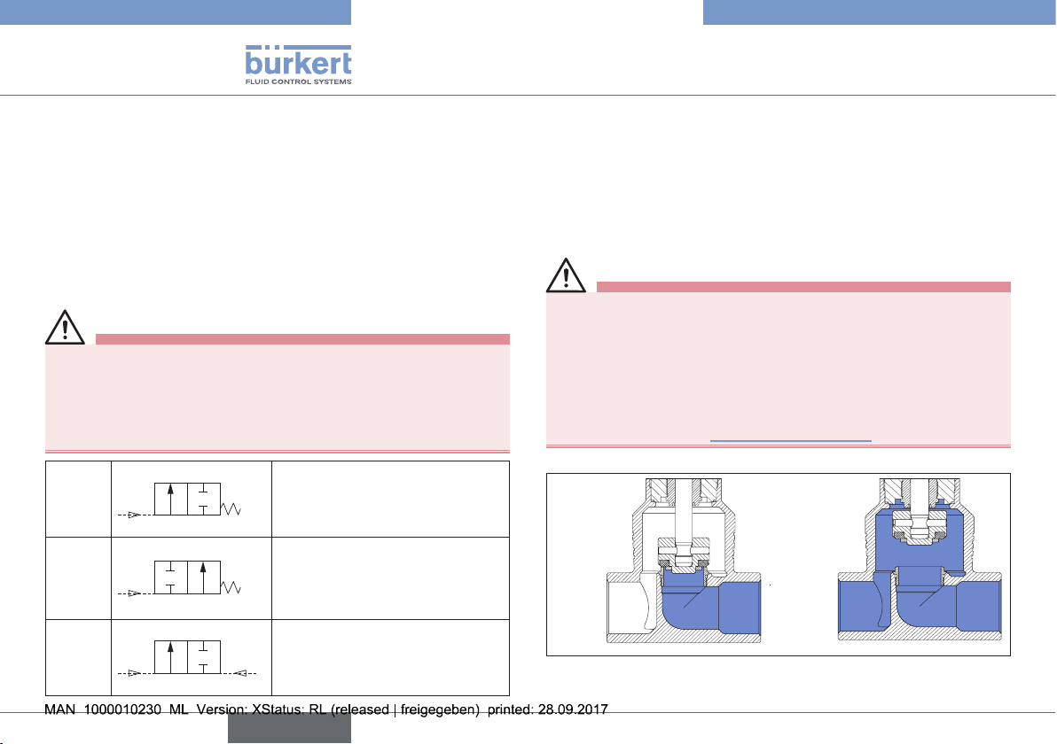
6.2.3 Flow direction above seat
The valve is closed by spring force (control function A, CFA) with
the medium flow. As the medium pressure is over the swivel plate, it
supports the closing process of the valve and also contributes to the
sealing of the valve seat. The valve is opened by the pilot pressure.
WARNING!
Risk of injury from water hammer.
A water hammer could crack the lines and device. Due to the risk of
water hammer, valves with a flow direction above seat must not
be used for liquid media.
▶ Consider the type of flow direction and the type of medium for
operation of the device.
To ensure complete opening, the minimum pilot pressure
must be applied.
Fig. 3: Flow direction above seat (closing with medium)
7 TECHNICAL DATA
7.1 Conformity
The globe control valve Type 2012 conforms with the EU Directives
according to the EU Declaration of Conformity.
7.2 Standards
The applied standards, which verify conformity with the EU Directives,
can be found on the EU-Type Examination Certificate and / or the EU
Declaration of Conformity.
7.3 Type label
Body material
Seal material
Flow direction
Flow 1 ← 2
2012 A 40,0 PTFE VA
FLNSCH Pmed 10bar
Pilot 5–10bar
Made in Germany
00146327 W39MS
Order number
Pilot pressure range
Type
Port connection
Fig. 4: Description of type label (example)
english
Seat orifice
Control function
Medium pressure
9
Page 10

Type 2012
Technical Data
7.4 Operating conditions
7.4.1 Temperature ranges
Actuator
size
[mm]
40 - 63 PA –10 ... see “Fig. 5” –10 ... see “Fig. 5”
80 - 125 PA –10 ... +180 °C –10 ... +60 °C
40 - 80 PPS –10 ... +180 °C +5 ... +140 °C
100 - 125 PPS –10 ... +180 °C +5 ... +90 °C, briefly up
Tab. 1: Temperature ranges
temperature
Fig. 5: Temperature range of the maximum medium and ambient
Actuator
material
Medium (for
Temperature ranges
Environment
1)
PTFE seal)
to max. +140 °C
1) If a pilot valve is used, the max. ambient temperature is + 55 °C.
Ambient
70
60
[°C]
50
40
30
20
100 120 140 160 180 200
∅ 50
∅ 40
∅ 63
Medium
temperature [°C]
temperature for PA actuators
7.4.2 Pressure ranges
Actuator
material
PA
PPS
Tab. 2: Maximum pilot pressure
Medium and pilot pressure for control function A, flow direction
below the seat (standard)
Maximum medium pressure / Minimum pilot pressure
Ori-
fice
40 50 63 80 100 125
10/15 15/4.0 16/3.9
20 6.5/4.0 11/3.9 16/4.5
25 5.2/3.9 11/4.5 16/5.0
32 6/4.5 14/5.0 16/4.4
40 4/4.5 9/5.0 12.5/4.4 16/3.2
50 2.5/4.5 6/5.0 7.2/4.4 10/3.2
65 12/5.6
Tab. 3: Medium and pilot pressure for CFA, standard
Actuator size
Max. pilot pressure
[mm]
40 - 100 10
125 7
40 - 100 10
125 7
Actuator size ø [mm]
[bar]
10
english
Page 11

Type 2012
Technical Data
Required minimum pilot pressure depending on medium
pressure.
The following graphs illustrate the required minimum pilot pressure
depending on the medium pressure for control functions A, B and I.
Control function A, flow direction above seat
Medium pressure [bar]
Pilot pressure [bar]
Fig. 6: Pressure graph, actuator ø 40 mm, control function A, flow
direction above seat
Medium pressure [bar]
Pilot pressure [bar]
Fig. 7: Pressure graph, actuator ø 50 mm, control function A, flow
direction above seat
Medium pressure [bar]
Pilot pressure [bar]
Fig. 8: Pressure graph, actuator ø 63 mm, control function A, flow
direction above seat
english
11
Page 12

Type 2012
Technical Data
Medium pressure [bar]
Pilot pressure [bar]
Fig. 9: Pressure graph, actuator ø 80 mm, control function A, flow
direction above seat
*
Medium pressure [bar]
Pilot pressure [bar]
Fig. 10: Pressure graph, actuator ø 100 mm, control function A,
flow direction above seat
12
english
Medium pressure [bar]
Pilot pressure [bar]
Fig. 11: Pressure graph, actuator ø 125 mm, control function A,
flow direction above seat
* Medium pressure max. 15 bar acc. to Pressure Equipment Directive
2014/68/EU for compressible fluids in Group 1 (hazardous gases and
vapors in accordance with Article 4 paragraph (1) c) i) first dash).
Page 13

Type 2012
Technical Data
Control functions B and I, flow direction below seat
Medium pressure [bar]
Medium pressure [bar]
Pilot pressure [bar]
Fig. 12: Pressure graph, actuator ø 40 mm, control functions B
and I, flow direction below seat
Medium pressure [bar]
Pilot pressure [bar]
Fig. 13: Pressure graph, actuator ø 50 mm, control functions B
and I, flow direction below seat
Pilot pressure [bar]
Fig. 14: Pressure graph, actuator ø 63 mm, control functions B
and I, flow direction below seat
Medium pressure [bar]
Pilot pressure [bar]
Fig. 15: Pressure graph, actuator ø 80 mm, control functions B
and I, flow direction below seat
english
13
Page 14

*
Medium pressure [bar]
Pilot pressure [bar]
Fig. 16: Pressure graph, actuator ø 100 mm, control functions B
and I, flow direction below seat
*
Type 2012
Technical Data
7.4.3 Media
Control medium neutral gases, air
Flow medium water, alcohol, fuel, hydraulic liquids,
saline solutions, lye, organic solvents
7.5 Control functions
Control function A Normally closed by spring action
Control function B Normally open by spring action
Control function I Actuating function via reciprocal
pressurization
7.6 Mechanical data
Materials
Valve body Stainless steel 316L
Actuator PA, PPS
Seal materials PTFE
(NBR, FKM and EPDM on request)
Packing gland PTFE (carbon-filled)
Medium pressure [bar]
Pilot pressure [bar]
Fig. 17: Pressure graph, actuator ø 125 mm, control functions B
and I, flow direction below seat
14
english
Page 15

Type 2012
Installation
8 INSTALLATION
8.1 Safety instructions
DANGER!
Risk of injury from high pressure.
▶ Before loosening the lines and valves, turn off the pressure and
vent the lines.
WARNING!
Risk of injury from improper installation.
▶ Installation may be carried out by authorized technicians only and
with the appropriate tools!
Risk of injury from unintentional activation of the system and
an uncontrolled restart.
▶ Secure system from unintentional activation.
▶ Following installation, ensure a controlled restart.
For control function I – Danger if pilot pressure fails.
For control function I control and resetting occur pneumatically. If
the pressure fails, no defined position is reached.
▶ To ensure a controlled restart, first pressurize the device with pilot
pressure, then switch on the medium.
Risk of injury from moving parts in the device.
▶ Do not reach into openings.
8.2 Before installation
Installation position: any, preferably with the actuator face up.
→ Before connecting the valve, ensure the lines are flush.
→ Observe direction of flow.
8.2.1 Preparatory work
→ Clean pipelines (sealing material, swarf, etc.).
Devices with welded body
Remove the actuator from the valve body:
→ Clamp the valve body in a holding device.
NOTE!
Damage to the seat seal or the seat contour!
▶ When removing the actuator, ensure that the valve is in open
position.
→ Control function A:
pressurize the lower control air connection with compressed air
(6 bar): valve opens.
→ Using a suitable open-end wrench, place the wrench flat on the
tube.
→ Unscrew the actuator from the valve body.
english
15
Page 16

Type 2012
Installation
8.3 Installation
WARNING!
Risk of injury from improper assembly.
Assembly with unsuitable tools or non-observance of the tightening
torque is dangerous as the device may be damaged.
▶ For installation use an open-end wrench, never a pipe wrench.
▶ Observe the tightening torque (see “Tab. 4: Tightening torques
of valve body / nipples”).
Dirt trap for devices with authorization in accordance with
DIN EN 161
In accordance with DIN EN 161 “Automatic shut-off valves for gas
burners and gas appliances” a dirt trap must be connected upstream
of the valve and prevent the insertion of a 1 mm plug gauge.
→ If the authorisation also applies to stainless steel bodies, the
same type of dirt trap must be attached in front of the globe
control valve.
8.3.1 Installation of the valve body
Welded bodies
→ Weld valve body in pipeline system.
Other body versions
→ Connect body to pipeline.
8.3.2 Install actuator (welded body)
Seal
Fig. 18: Seal
→ Check the seal and if required, replace it.
WARNING!
Danger if incorrect lubricants used!
Unsuitable lubricant may contaminate the medium. In oxygen
applications there is a risk of an explosion!
▶ In specific applications, e.g. oxygen or analysis applications,
use appropriately authorised lubricants only.
→ Grease nipple thread before re-installing the actuator (e.g. with
Klüber paste UH1 96-402 from Klüber).
NOTE!
Damage to the seat seal or the seat contour.
▶ When installing the actuator, ensure that the valve is in open
position.
→ Control function A:
Pressurize lower control air connection with compressed air
(6 bar) so that the swivel plate is lifted off the valve seat and is
not damaged when screwed in.
16
english
Page 17

Type 2012
Installation
→ Screw actuator into the valve body.
Tightening torques of valve body / nipples
Nominal diameter Tightening torque (Nm)
15 45 ± 3
20 50 ± 3
25 60 ± 3
32 65 ± 3
40 65 ± 3
50 70 ± 3
65 70 ± 3
Tab. 4: Tightening torques of valve body / nipples
8.3.3 Rotating the actuator
The position of the connections can be aligned steplessly by rotating
the actuator through 360°.
NOTE!
Damage to the seat seal or the seat contour.
▶ When rotating the actuator, ensure that the valve is in open
position.
→ Clamp the valve body in a holding device
(applies only to valves which have not yet been installed).
→ Control function A: pressurize the lower control air connection
with compressed air (6 bar): valve opens.
→ Counter on the flats of the nipple with a suitable open-end wrench.
→ Place suitable open-end wrench on the hexagon of the actuator.
WARNING!
Risk of injury from discharge of medium and pressure.
If the direction of rotation is wrong, the body interface may become
detached.
▶ Rotate the actuator module in the specified direction only (see
“Fig. 19”).
→ By turning the open-end wrench clockwise (viewed from above),
move the actuator into the required position.
Open-end wrench
Fig. 19: Turning with open-end wrench
english
17
Page 18

Type 2012
Installation
8.4 Pneumatic connection
DANGER!
Danger – high pressure in the equipment.
▶ Before loosening the lines and valves, turn off the pressure and
vent the lines.
WARNING!
Risk of injury from unsuitable connection hoses.
Hoses which cannot withstand the pressure and temperature range
may result in hazardous situations.
▶ Use only hoses which are authorised for the indicated pressure
and temperature range.
▶ Observe the data sheet specifications from the hose manufacturers.
For control function I – Danger if pilot pressure fails.
For control function I control and resetting occur pneumatically. If
the pressure fails, no defined position is reached.
▶ To ensure a controlled restart, first pressurize the device with pilot
pressure, then switch on the medium.
If the position of the pilot air ports for installation of the hoses
is unfavorable, these can be aligned steplessly by rotating
the actuator through 360°.
Control function A
→ Connect the control medium to the lower control air connection
of the actuator.
Control function B
→ Connect the control medium to the upper control air connection
of the actuator.
Control function I
→ Connect the control medium to the lower and upper control air
connection of the actuator.
If used in an aggressive environment, we recommend conveying all free pneumatic connections into a neutral atmosphere with the aid of a pneumatic hose.
Control air hose:
6/4 mm or 1/4” control air hoses can be used.
8.5 Removal
DANGER!
Risk of injury from discharge of medium and pressure!
It is dangerous to remove a device which is under pressure due to
the sudden release of pressure or discharge of medium.
▶ Before removing a device, switch off the pressure and vent the
lines.
→ Loosen the pneumatic connection.
→ Remove the device.
18
english
Page 19

Type 2012
Maintenance, Cleaning
9 MAINTENANCE, CLEANING
9.1 Safety instructions
DANGER!
Danger – high pressure in the equipment.
▶ Before loosening the lines and valves, turn off the pressure and
vent the lines.
Risk of injury due to electrical shock.
▶ Before reaching into the system, switch off the power supply and
secure to prevent reactivation!
▶ Observe applicable accident prevention and safety regulations
for electrical equipment!
WARNING!
Risk of injury from improper maintenance.
▶ Maintenance may be performed by authorised technicians only!
▶ To screw on or unscrew valve body or actuator, use an open-end
wrench, never a pipe wrench, and observe tightening torques.
Risk of injury from unintentional activation of the system and
an uncontrolled restart.
▶ Secure system from unintentional activation.
▶ Following maintenance, ensure a controlled restart.
WARNING!
For control function I – Danger if pilot pressure fails.
For control function I control and resetting occur pneumatically.
If the pressure fails, no defined position is reached.
▶ To ensure a controlled restart, first pressurize the device with pilot
pressure, then switch on the medium.
Risk of injury from moving parts in the device.
▶ Do not reach into openings.
9.2 Maintenance work
Actuator:
The actuator of the globe control valve is maintenance-free provided
it is used according to these operating instructions.
Wearing parts of the globe control valve:
Parts which are subject to natural wear:
• Valve seat,
• Seals.
→ If leaks occur, replace the particular wearing part with an appro-
priate spare part.
Visual inspection:
Perform regular visual inspections according to the application
conditions:
→ Check media connections for leaks.
→ Check release bore on the tube for leaks.
english
19
Page 20

Release bore
Fig. 20: Release bore
9.2.1 Cleaning
Commercially available cleaning agents can be used to clean the
outside.
NOTE!
Avoid causing damage with cleaning agents.
▶ Before cleaning, check that the cleaning agents are compatible
with the body materials and seals.
9.3 Replacing the valve seat
Remove the actuator from the valve body
→ Clamp the valve body in a holding device.
NOTE!
Damage to the seat seal or the seat contour.
▶ When removing the actuator, ensure that the valve is in open
position.
Type 2012
Maintenance, Cleaning
→ Control function A: pressurize the lower control air connection
with compressed air (6 bar): valve opens.
→ Using a suitable open-end wrench, place the wrench flat on the
tube.
→ Unscrew the actuator from the valve body.
Replacing valve seat
→ Unscrew old valve seat using the installation tool and open-end
wrench.
→ Clean thread and sealing surface in the body using compressed air.
→ Select tool insert and screw into the installation tool.
Installation tool
Tool insert
(according to nominal
width of seat)
Valve seat
Fig. 21: Replacing the valve seat
20
english
Page 21

Type 2012
Malfunctions
→ Attach new valve seat to the installation tool.
→ Grease thread with a lubricant (e.g. Klüber paste UH1 96-402).
→ Place attached valve seat on the body thread and screw on by
hand.
→ Using a torque wrench, tighten to the specified tightening torque
(see “Tab. 5”).
Tightening torque for installation of seat
Screw connection Tightening torques
Seat Body
DN 4-15 DN 15 25 20 +3
DN 20 DN 20 35 28 +3
DN 25 DN 25 50 40 +5
DN 32 DN 32 80 65 +5
DN 40 DN 40 100 85 +8
DN 50 DN 50 120 120 +8
DN 65 DN 65 150 150 +10
DN 80 DN 80 180 180 +10
DN 100 DN 100 220 220 +10
Tab. 5: Tightening torque for installation of seat
Uncoated
seats
Coated
seats
Tolerance
10 MALFUNCTIONS
Malfunction Reason Remedial action
Actuator
does not
switch
Valve is not
sealed
Valve is
leaking on
the release
bore
Tab. 6: Malfunctions
Pilot air port
interchanged
Pilot pressure too low
Medium pressure too
high
Flow direction reversed
Dirt between seal and
valve seat
Seat seal worn
Flow direction reversed
Medium pressure too
high
Pilot pressure too low
Packing gland worn
→ Connect lower (CFA,
CFI) or upper (CFB,
CFI) control air
connection
→ Observe pressure
specifications on the
type label
→ Observe direction
arrow on the body
→ Installing dirt trap
→ Installing new seat seal
→ Observe direction
arrow on the type label
→ Observe pressure
specifications on the
type label
→ Renew packing gland
or replace actuator
english
21
Page 22

Type 2012
Replacement parts
11 REPLACEMENT PARTS
CAUTION!
Risk of injury and/or damage by the use of incorrect parts.
Incorrect accessories and unsuitable replacement parts may cause
injuries and damage the device and the surrounding area.
▶ Use only original accessories and original replacement parts from
Bürkert.
11.1 Replacement part sets
The following spare part sets are available for the globe control valve
Type 2012:
• Seal set,
• Valve set,
• Valve fittings (valve set + seat).
The order numbers of the spare parts and the installation
instructions can be found in the spare parts operating
instructions on our website:
www.burkert.com → Type 2012.
11.2 Overview of spare parts
Seal set
Fittings set
(valve set + seat)
1
Valve set
3
2
22
Fig. 22: Overview of spare parts
english
Page 23

Type 2012
Transport, Storage, Disposal
12 TRANSPORT, STORAGE,
DISPOSAL
NOTE!
Transport damages.
Inadequately protected equipment may be damaged during transport.
• During transportation protect the device against wet and dirt in
shock-resistant packaging.
• Avoid exceeding or dropping below the permitted storage
temperature.
Incorrect storage may damage the device.
• Store the device in a dry and dust-free location!
• Storage temperature -20 – +65 °C.
Damage to the environment caused by device components
contaminated with media.
• Dispose of the device and packaging in an environmentally
friendly manner.
• Observe applicable regulations on disposal and the environment.
Note:
Observe national waste disposal regulations.
english
23
Page 24

Type 2012
24
english
Page 25

Page 26

www.burkert.com
 Loading...