

Type 8228
ELEMENT
Inductive conductivity meter
Induktives Leitfähigkeits-Messgerät
Conductimètre inductif
Operating Instructions
Bedienungsanleitung
Manuel d‘utilisation

We reserve the right to make technical changes without notice.
Technische Änderungen vorbehalten.
Sous réserve de modifications techniques.
© Bürkert SAS, 2014 - 2016
Operating Instructions 1603/2_EU-ML 00565588 / Original FR

Type 8228
Contents
1 ABOUT THIS MANUAL .....................................................................................................................................................................6
1.1 Definition of the word "device" .......................................................................................................................................6
1.2 Validity of the manual ..........................................................................................................................................................6
1.3 Symbols used ..........................................................................................................................................................................6
2 INTENDED USE ....................................................................................................................................................................................7
3 BASIC SAFETY INFORMATION ....................................................................................................................................................8
4 GENERAL INFORMATION .............................................................................................................................................................10
4.1 Manufacturer's address and international contacts .........................................................................................10
4.2 Warranty conditions ...........................................................................................................................................................10
4.3 Information on the Internet ............................................................................................................................................10
5 DESCRIPTION ....................................................................................................................................................................................11
5.1 Area of application .............................................................................................................................................................11
5.2 Knowing the device ...........................................................................................................................................................11
5.3 Knowing the available versions ..................................................................................................................................12
5.4 Understanding the name plate .................................................................................................................................... 13
6 TECHNICAL DATA .............................................................................................................................................................................14
6.1 Operating conditions ........................................................................................................................................................14
6.2 Conformity to standards and directives .................................................................................................................14
6.3 Fluid data .................................................................................................................................................................................15
6.4 Mechanical data ...................................................................................................................................................................16
6.5 Dimensions of device .......................................................................................................................................................16
6.6 Electrical data .......................................................................................................................................................................17
6.7 Data of the connectors and wires ..............................................................................................................................18
7 ASSEMBLY ...........................................................................................................................................................................................19
7.1 Safety instructions .............................................................................................................................................................19
7.2 Removing the cover ...........................................................................................................................................................19
7.3 Mounting the cover ............................................................................................................................................................20
7.4 Mounting the display module .......................................................................................................................................20
7.5 Dismounting the display module ...............................................................................................................................21
English
3
Type 8228
8 INSTALLATION AND WIRING ......................................................................................................................................................22
8.1 Safety instructions .............................................................................................................................................................22
8.2 Installing a 8228 with a G2'' process connection in the pipe ......................................................................23
8.3 Installing a 8228 with a 2'' clamp process connection in the pipe............................................................................24
8.4 Wiring the device .................................................................................................................................................................25
8.4.1 Assembling the male or female connector (see chap. "11 Accessories and spare parts") 2 6
8.4.2 Making the installation equipotential ..............................................................................................26
8.4.3 Wiring a version with a single M12 fixed connector ..................................................................27
8.4.4 Wiring a version with 2 M12 fixed connectors ............................................................................ 30
9 OPERATING AND COMMISSIONING .....................................................................................................................................33
9.1 Safety instructions .............................................................................................................................................................33
9.2 Knowing the operating levels .......................................................................................................................................33
9.3 Using the navigation button .......................................................................................................................................... 34
9.4 Using the dynamic functions ........................................................................................................................................36
9.5 Entering a numerical value (example) .....................................................................................................................36
9.6 Browsing in a menu (example) ...................................................................................................................................37
9.7 Knowing the display ..........................................................................................................................................................37
9.7.1 Knowing the icons and LEDs ..........................................................................................................37
9.7.2 Knowing the display at the power-up of the device ...................................................................38
9.8 Knowing the Process level ............................................................................................................................................39
9.9 Accessing the Configuration level .............................................................................................................................40
9.10 Knowing the structure of the menus of the Configuration level ...............................................................41
9.11 Knowing the Parameters menu ..................................................................................................................................45
9.11.1 Transferring data from one device to another .............................................................................. 45
9.11.2 Setting the date and time .................................................................................................................45
9.11.3 Modifying the PARAM menu access code ...................................................................................46
9.11.4 Restoring the default parameters of the Process level and the outputs ............................... 46
9.11.5 Setting the data displayed in the Process level ..........................................................................47
9.11.6 Displaying of the lowest and highest values measured .............................................................48
9.11.7 Setting the display contrast and brightness ................................................................................48
9.11.8 Choosing the output wiring mode ..................................................................................................49
4
English

Type 8228
9.11.9 Setting the parameters of the current outputs ............................................................................49
9.11.10 Setting the parameters of the transistor outputs ........................................................................50
9.11.11 Choosing the type of temperature compensation ......................................................................52
9.12 Knowing the Calibration menu ....................................................................................................................................53
9.12.1 Activating/deactivating the Hold function ..................................................................................... 53
9.12.2 Modifying the Calibration menu access code .............................................................................53
9.12.3 Adjusting the current outputs .......................................................................................................... 54
9.12.4 Calibrating the sensor ....................................................................................................................... 54
9.12.5 Entering an offset for the temperature measurement ................................................................60
9.13 Knowing the Diagnostic menu ....................................................................................................................................60
9.13.1 Modifying the Diagnostic menu access code ..............................................................................60
9.13.2 Monitoring the fluid conductivity ..................................................................................................... 60
9.13.3 Monitoring the fluid temperature ..................................................................................................... 61
9.14 Knowing the Test menu ...................................................................................................................................................62
9.14.1 Modifying the Test menu access code .......................................................................................... 62
9.14.2 Checking the outputs functions ......................................................................................................62
9.14.3 Checking the outputs behaviour .....................................................................................................63
9.15 Knowing the Information menu ...................................................................................................................................64
9.15.1 Reading the cause of events linked to icons ...............................................................................64
9.15.2 Reading the software versions ........................................................................................................64
9.15.3 Reading some identification informations of the device ............................................................64
10 MAINTENANCE AND TROUBLESHOOTING .......................................................................................................................65
10.1 Safety instructions .............................................................................................................................................................65
10.2 Cleaning the device ...........................................................................................................................................................65
10.3 Solving a problem ..............................................................................................................................................................66
11 ACCESSORIES AND SPARE PARTS ......................................................................................................................................70
12 PACKAGING, TRANSPORT ..........................................................................................................................................................70
13 STORAGE ..............................................................................................................................................................................................71
14 DISPOSAL OF THE PRODUCT ..................................................................................................................................................71
English
5
Type 8228
About this manual
1 ABOUT THIS MANUAL
This manual describes the entire life cycle of the device. Please keep this manual in a safe place, accessible to all
users and any new owners.
This manual contains important safety information.
Failure to comply with these instructions can lead to hazardous situations. Pay attention in particular to the
chapters "Basic safety information" and "Intended use".
▶ Whatever the version of the device, this manual must be read and understood.
▶ When the symbol
is marked inside or outside the device, carefully read the manual.
1.1 Definition of the word "device"
The word "device" used within this manual refers to the conductivity meter type 8228.
1.2 Validity of the manual
The manual is valid for the conductivity meter type 8228 version V2. This information of version is available on the
name plate, see chap. 5.4.
1.3 Symbols used
DANGER
Warns against an imminent danger.
▶ Failure to observe this warning can result in death or in serious injury.
WARNING
Warns against a potentially dangerous situation.
▶ Failure to observe this warning can result in serious injury or even death.
CAUTION
Warns against a possible risk.
▶ Failure to observe this warning can result in substantial or minor injuries.
NOTE
Warns against material damage.
▶ Failure to observe this warning may result in damage to the device or system.
Indicates additional information, advice or important recommendations.
Refers to information contained in this manual or in other documents.
6
English
Type 8228
About this manual
▶ Indicates an instruction to be carried out to avoid a danger, a warning or a possible risk.
→ Indicates a procedure to be carried out.
Indicates the result of a specific instruction.
2 INTENDED USE
Use of the device that does not comply with the instructions could present risks to people, nearby
installations and the environment.
The 8228 conductivity meter is intended solely for the measurement of the conductivity.
▶ Use this device in compliance with the characteristics and commissioning and use conditions specified in the
contractual documents and in the user manual.
▶ Never use the conductivity meter type 8228 for security applications.
▶ Protect this device against electromagnetic interference, ultraviolet rays and, when installed outdoors, the
effects of climatic conditions.
▶ Only operate a device in perfect working order.
▶ Requirements for the safe and proper operation of the device are proper transport, storage and installation, as
well as careful operation and maintenance.
▶ Only use the device as intended.
English
7
Type 8228
Basic safety information
3 BASIC SAFETY INFORMATION
This safety information does not take into account:
• any contingencies or occurences that may arise during installation, use and maintenance of the devices.
• the local safety regulations for which the operating company is responsible including the staff in charge of
installation and maintenance.
Risk of injury due to electrical voltage.
▶ If a 12-36 V DC powered version is installed either in a wet environment or outdoors, all the electrical volt-
ages must be of max. 35 V DC.
▶ Disconnect the electrical power for all the conductors and isolate it before carrying out work on the system.
▶ All equipment connected to the 8619 shall be double insulated with respect to the mains according to the
standard IEC 61010-1:2010.
▶ Observe all applicable accident protection and safety regulations for electrical equipment.
Risk of injury due to high pressure in the installation.
▶ Stop the circulation of fluid, cut off the pressure and drain the pipe before loosening the process connections.
Risk of injury due to high fluid temperatures.
▶ Use safety gloves to handle the device.
▶ Stop the circulation of fluid and drain the pipe before loosening the process connections.
Risk of injury due to the nature of the fluid.
▶ Respect the regulations on accident prevention and safety relating to the use of aggressive fluids.
8
English
Type 8228
Basic safety information
Various dangerous situations
To avoid injury take care:
▶ not to use the device for the measurement of the conductivity of gases.
▶ not to use the device in explosive atmospheres.
▶ not to use the device in an environment incompatible with the materials it is made of.
▶ not to use fluid that is incompatible with the materials the device is made of.
▶ not to subject the device to mechanical loads.
▶ not to make any modifications to the device.
▶ to prevent any unintentional power supply switch-on.
▶ to carry out the installation and maintenance work by qualified and skilled staff with the appropriate tools.
▶ to guarantee a defined or controlled restarting of the process, after a power supply interruption.
▶ to use the device only if in perfect working order and in compliance with the instructions provided in the
manual.
▶ to observe the general technical rules when installing and using the device.
NOTE
The device may be damaged by the fluid in contact with.
▶ Systematically check the chemical compatibility of the component materials of the device and the fluids likely
to come into contact with it (for example: alcohols, strong or concentrated acids, aldehydes, alkaline compounds, esters, aliphatic compounds, ketones, halogenated aromatics or hydrocarbons, oxidants and chlorinated agents).
NOTE
Elements / Components sensitive to electrostatic discharges
▶ This device contains electronic components sensitive to electrostatic discharges. They may be damaged if
they are touched by an electrostatically charged person or object. In the worst case scenario, these components are instantly destroyed or go out of order as soon as they are activated.
▶ To minimise or even avoid all damage due to an electrostatic discharge, take all the precautions described in
the EN 61340-5-1 norm.
▶ Do not touch any of the live electrical components.
English
9

Type 8228
General information
4 GENERAL INFORMATION
4.1 Manufacturer's address and international contacts
To contact the manufacturer of the device, use following address:
Bürkert SAS
Rue du Giessen
BP 21
F-67220 TRIEMBACH-AU-VAL
You may also contact your local Bürkert sales office.
The addresses of our international sales offices are available on the internet at:
www.burkert.com
4.2 Warranty conditions
The condition governing the legal warranty is the conforming use of the device in observance of the operating
conditions specified in this manual.
4.3 Information on the Internet
You can find the user manuals and technical data sheets regarding the type 8228 at:
www.burkert.com
10
English
Type 8228
Description
5 DESCRIPTION
5.1 Area of application
The device is intended to measure the conductivity. Thanks to one or two fully adjustable transistor outputs, the
device can be used to switch a solenoid valve, activate an alarm and, thanks to one or two 4-20-mA current outputs,
establish one or two control loops.
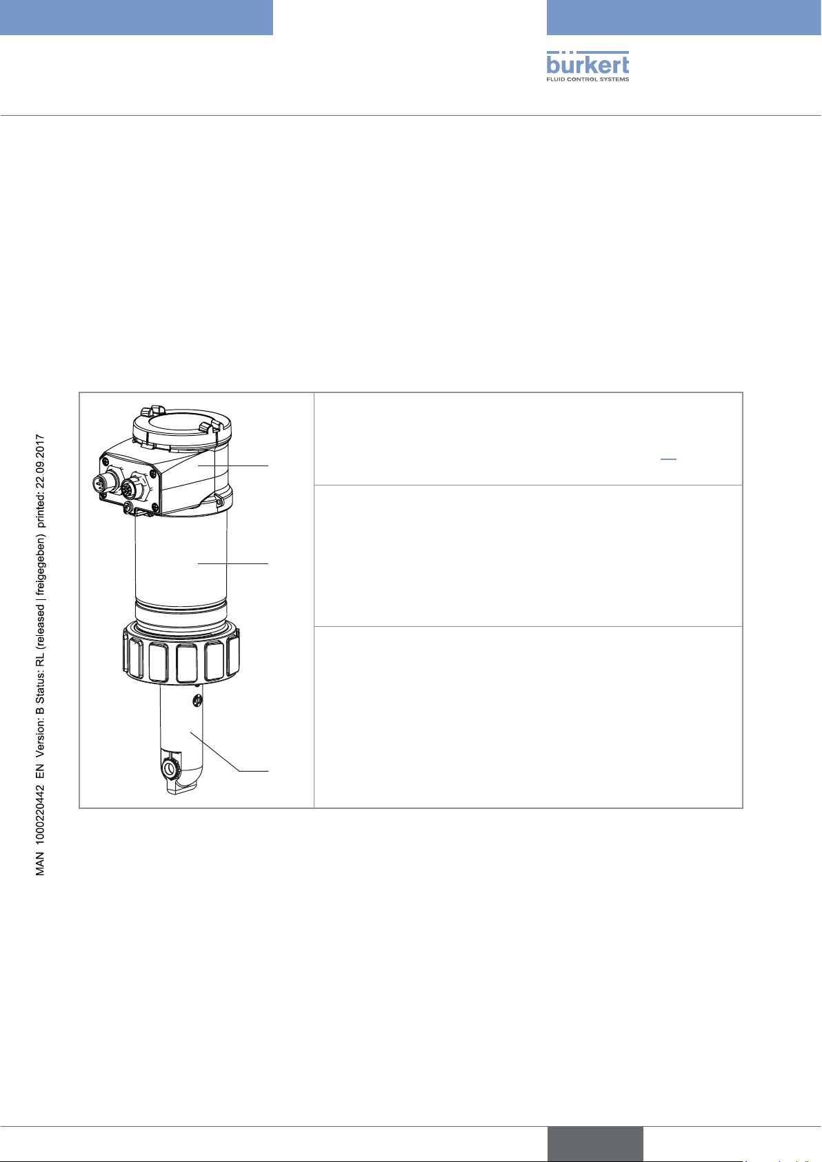
5.2 Knowing the device
The device comprises:
A: an electrical housing which can include a display module. The display
module has a navigation button to read and/or configure the parameters
of the device. The display module is not delivered with all the versions
of the device but it is available as an accessory (see chap. 11).
A
B: An electronic module for the acquisition / conversion of the measurable variables:
- acquisition of the conductivity in µS/cm,
B
C
The device operates on a 3 wire system and needs a 12-36 V DC power supply.
The electrical connection is made, depending on the version, via a 5 pin, male, M12 fixed connector or via a 5 pin,
male, M12 fixed connector and a a 5 pin, female, M12 fixed connector.
- acquisition of the temperature,
- calculation of the conductivity at a temperature of 25 °C,
- conversion of the conductivity into a resistivity at 25 °C in Ohm/cm.
C: a conductivity sensor comprised of:
- a pair of magnetic coils,
- a sensor holder in PP, PVDF or PEEK equipped with an integrated
temperature probe.
The conductivity sensor is pined together with the electronic module
and cannot be dismantled.
The conductivity sensor comprises a temperature probe to compensate
the temperature when measuring the conductivity.
English
11
Type 8228
PEEK
EPDM
Description
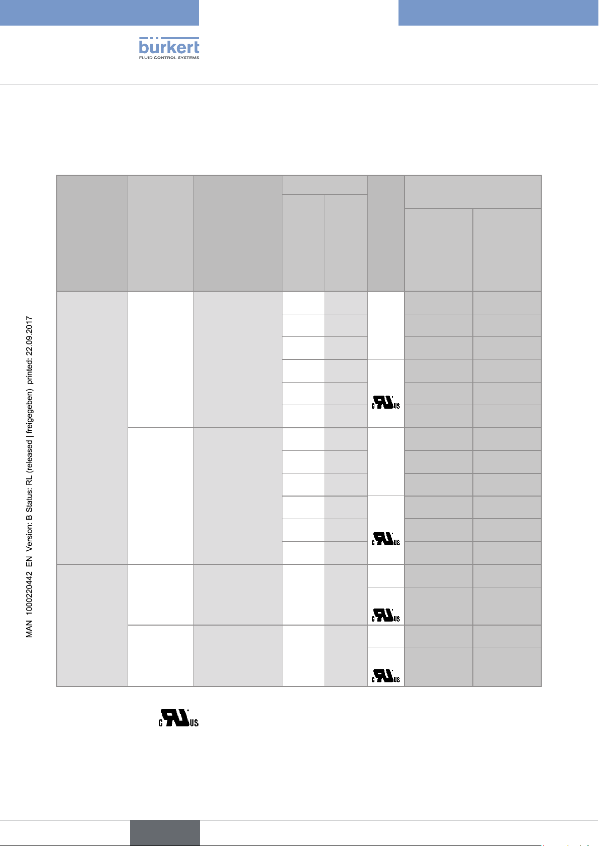
5.3 Knowing the available versions
The following versions of the device are available. Each version is available without or with the display module.
All versions of the device require a power supply of 12-36 V DC.
Process
connection
Outputs
G2’’ 1 x transistor,
NPN/PNP, +
1 x 4-20 mA
2 x transistor,
NPN/PNP, +
2 x 4-20 mA
Electrical
connection
Male 5-pin M12
fixed connector
Male 5-pin M12
fixed connector +
female 5-pin M12
fixed connector
Materials
Conductivity sensor
holder
PP FKM
PVDF FKM
PEEK FKM
PP FKM
PVDF FKM
PEEK FKM
PP FKM
PVDF FKM
PEEK FKM
PP FKM
PVDF FKM
PEEK FKM
Seal of the
1)
1)
1)
1)
1)
1)
1)
1)
1)
1)
1)
1)
UL
conductivity sensor
no
yes
no
yes
Order code
2)
without
display
module
with display
module
565 601 566 601
565 603 566 603
565 605 566 605
565 611 566 611
565 613 566 613
565 615 566 615
565 602 566 602
565 604 566 604
565 606 566 606
565 612 566 612
565 614 566 614
565 616 566 616
12
Clamp 2’’
(according to
1 x transistor
NPN/PNP +
1 x 4...20 mA
Male 5-pin M12
fixed connector
PEEK EPDM
ASME BPE)
2 x transistors
NPN/PNP +
2 x 4...20 mA
Male 5-pin M12
fixed connector +
female 5-pin M12
fixed connector
1)
Seal delivered with the device.
2)
identified by the logo on the name plate of the device.
English
no
yes
no
yes
567 200 567 478
567 480 567 482
567 199 567 479
567 481 567 483
Type 8228
2
31
1011
12
13
14
16
15
18
17
4
Description
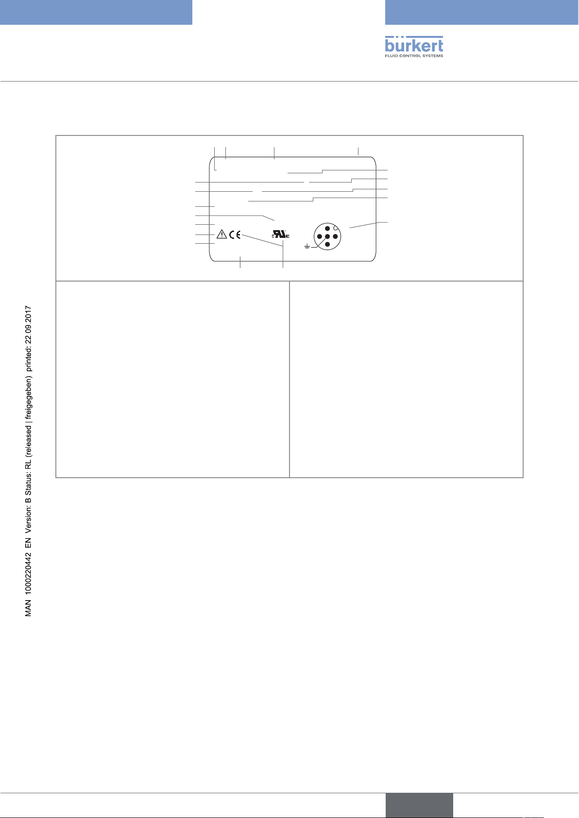
5.4 Understanding the name plate
8228 Inductive Conductivity Meter V2
Supply: 12-36V 40W max.
Output: 1x 4-20mA 1xTrans 700mA max.
Cell: PEEK Range 100 µS/cm - 2 S/cm
Process: Temp -15 to 130°C
PN 10, limited by fitting material and fluid temp.
IP65-IP67 W41MN
S-N:1000
00566615
2:NPN/PNP1
3:0V
4:I1
1:V+
5
6
7
8
9
1. Supply voltage
2. Type of the device
3. Measurable variable
4. Version
5. Max. power consumption
6. Max. current available at the transistor output(s)
7. Conductivity measuring range
8. Fluid temperature range
9. Pin assignment of the M12 fixed connector(s)
10. Conformity logos
Fig. 1: Name plate of the device (example)
11. Order code
12. Serial number
13. Warning: Before using the device, take into account
the technical specifications described in these
operating instructions.
14. Protection class
15. Construction code
16. Nominal pressure of the fluid
17. Material of the conductivity sensor holder
18. Available outputs
13
English
Type 8228
Technical data
6 TECHNICAL DATA
6.1 Operating conditions
Ambient temperature -10 to +60 °C
Air humidity < 85 %, non condensated
Height above sea level max. 2000 m
Installation category acc. to UL 61010-1 Category I
Degree of pollution acc. to EN 61010-1 Degree 2
Protection class acc. to EN 60529 IP65 and IP67 with connectors plugged in and
tightened and electronic module cover fully closed and
sealed
6.2 Conformity to standards and directives
The device conforms to the EC directives through the following standards:
• EMC: EN 61000-6-2, EN 61000-6-3 and Annex1, EN 61326-1-4 (Table 2, Immunity for industrial
environment)
• Environnemental testing: Vibration: EN 60068-2-6, Shock: EN 60068-2-27.
• Pressure: conforms to the requirements of article 3§3 of the pressure equipment directive 97/23/CE.
According to this directive, the product can only be used in the following cases (depending on max. pressure,
pipe diameter and fluid):
Type of fluid Conditions
Fluid group 1, par. 1.3.a Forbidden
Fluid group 2 par. 1.3.a DN ≤ 32
or DN > 32 and PNxDN ≤ 1000
Fluid group 1 par. 1.3.b PNxDN ≤ 2000
Fluid group 2 par. 1.3.b DN ≤ 200
or PN ≤ 10
The UL devices with variable key PE72 comply with the following standards:
• UL 61010-1
• CRN/CSA-C22.2 n° 61010-1.
14
• approval: only for version with PVDF sensor holder and with EPDM or FKM seal.
English
Type 8228
T (°C)
P (bar)
Technical data
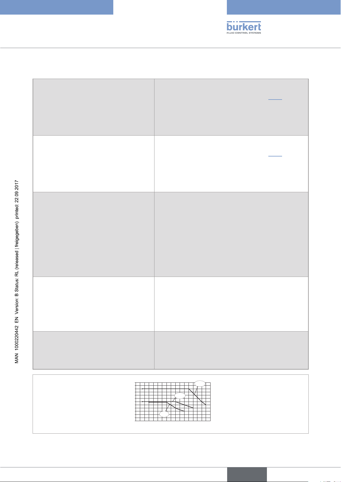
6.3 Fluid data
Fluid temperature
• 8228 with conductivity sensor in PVDF
• 8228 with conductivity sensor in PP
• 8228 with conductivity sensor in PEEK
Fluid pressure
• 8228 with conductivity sensor in PVDF
• 8228 with conductivity sensor in PP
• 8228 with conductivity sensor in PEEK
Conductivity measurement
• Measurement range
• Resolution
• Measurement deviation ("measurement bias" as
defined in the standard JCGM 200:2012)
The fluid temperature may be restricted by the fluid pressure,
the material the conductivity sensor holder is made of and the
material the S020 fitting used is made of (see Fig. 2).
• -15 °C to +100 °C
• 0 °C to +80 °C
• -15 °C to +130 °C
The fluid pressure may be restricted by the fluid temperature,
the material the conductivity sensor holder is made of and the
material the S020 fitting used is made of (see Fig. 2).
• PN6
• PN6
• PN10
• 100µS/cm to 2 S/cm.
• 0,1 µS/cm
• ±(2% of the measured value + 5µS/cm)
• Linearity
• Repeatability
• Response time (90%)
• ±2%
• ±(0,2% of the measured value + 2µS/cm)
• from 3 s (without filter) to 40 s (with "slow" filter)
Temperature measurement
• Measurement range
• Resolution
• Measuring uncertainty
• Response time (90%)
• -40 °C to +150 °C, restricted by the conductivity sensor used
• 0.1 °C
• ±1 °C
• < 280 s (without filter)
Temperature compensation • none or
• according to a predefined curve (NaCl, NaOH, HNO
H2SO4) or
• or according to a curve defined especially for your process
12
11
10
9
8
7
6
5
4
3
2
1
0
-200+20 +40 +60 +80 +100 +140
PP
PVDF
PEEK
+120
3
or
Fig. 2: Fluid temperature - pressure dependency for a 8228 with a conductivity sensor in PVDF or a conductivity sensor
in PP or a conductivity sensor in PEEK, with a fitting S020 in stainless steel
English
15
Type 8228
Technical data
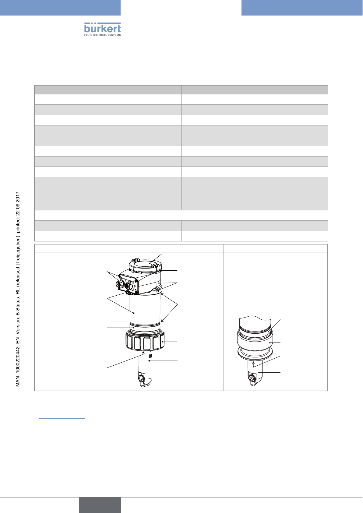
6.4 Mechanical data
Part Material
Box / seals stainless steel 316L 1.4404, PPS / EPDM
Cover / seal PC / silicone
Display module PC / PBT
M12 fixed connector • nickel-plated brass (stainless steel on request)
• stainless steel for 2'' clamp process connection
Fixed connector holder stainless steel 316L
Screws stainless steel
Nut PC
Conductivity sensor holder / seal • PVDF / FKM (in contact with the fluid)
• PP / FKM (in contact with the fluid)
• PEEK / FKM (in contact with the fluid)
Version with 2'' clamp process connection
Adapter for clamp stainless steel 316L 1.4404
Conductivity sensor holder /seal PEEK / EPDM (in contact with the fluid)
G2'' process connection 2'' clamp process connection
PC
Nickel-plated brass
(or stainless steel)
Stainless steel
PPS
FKM
silicone
PPS
EPDM
PC
PVDF or PP or
PEEK
PPS
Stainless
steel
EPDM
PEEK only
16
Fig. 3: Materials of the device
• Mechanical data of fittings: please refer to the technical data sheets of the related fittings, avalaible at:
www.burkert.com
6.5 Dimensions of device
→ please refer to the technical data sheets regarding the type 8228 avalaible at: www.burkert.com
English
Type 8228
Technical data
6.6 Electrical data
Power supply 12-36 V DC • filtered and regulated
• SELV circuit, with a safe energy level
• oscillation rate: ±10 %
Power source (not supplied) • limited power source according to paragraph 9.3 of
EN 61010-1 standard
• or class 2 source according to UL 1310/1585 and
EN 60950-1 standards
Current consumption
• without the consumption of the current outputs and
the transistor outputs
• with the consumption of the current outputs and the
transistor outputs
Transistor output
• type
• NPN output
• PNP output
• protection
Current output
• specification
• uncertainty of the output value
• type of connection
• max. 1 W (max. 25 mA at 12 V DC; starting current
~100 mA)
• max. 40 W (max. 1 A for the transistor outputs)
polarized
• NPN (/sink) or PNP(/source) (through wiring and
through parameterizing)
• 1-36 V DC, 700 mA max. (or 500 mA max. if 2 transistor outputs are wired)
• supply voltage, 700 mA max. (or 500 mA max. if 2
transistor outputs are wired)
• galvanically insulated, protected against overvoltages,
polarity reversals and short-circuits
• 4-20 mA, sink or source (through wiring and through
parametrizing), 22 mA to indicate a fault (can be
parametered)
• 1% of the full scale
• 3-wire
• max. loop impedance
• Response time (10 % - 90 %)
• 1100 W at 36 V DC, 610 W at 24 V DC, 100 W at
12 V DC
• 150 ms (default value)
17
English
Type 8228
Technical data
6.7 Data of the connectors and wires
Number of fixed connectors Type of connector
1 male M12 fixed connector 5-pin M12 female connector (not supplied).
For the female M12 connector with order code 917116, use a
shielded cable:
• diameter: 3 to 6.5 mm
1 male M12 fixed connector and 1 female M12
fixed connector
• wire cross section: max. 0.75 mm
2
5-pin M12 female connector (not supplied) and 5-pin M12 male
connector (not supplied).
For the female M12 connector with order code 917116 and the
male M12 connector with order code 560946, use a shielded
cable:
• diameter: 3 to 6.5 mm
• wire cross section: max. 0.75 mm
2
18
English
Type 8228
Assembly
7 ASSEMBLY
7.1 Safety instructions
DANGER
Risk of injury due to electrical voltage.
▶ Shut down and isolate the electrical power source before carrying out work on the system.
▶ Observe all applicable accident protection and safety regulations for electrical equipment.
WARNING
Risk of injury due to non-conforming assembly.
▶ The device must only be assembled by qualified and skilled staff with the appropriate tools.
Risk of injury due to unintentional switch on of power supply or uncontrolled restarting of the
installation.
▶ Take appropriate measures to avoid unintentional activation of the installation.
▶ Guarantee a set or controlled restarting of the process after assembling the device.
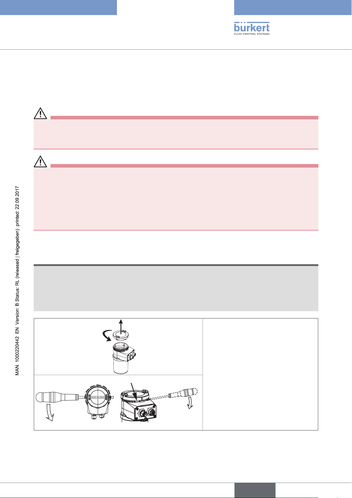
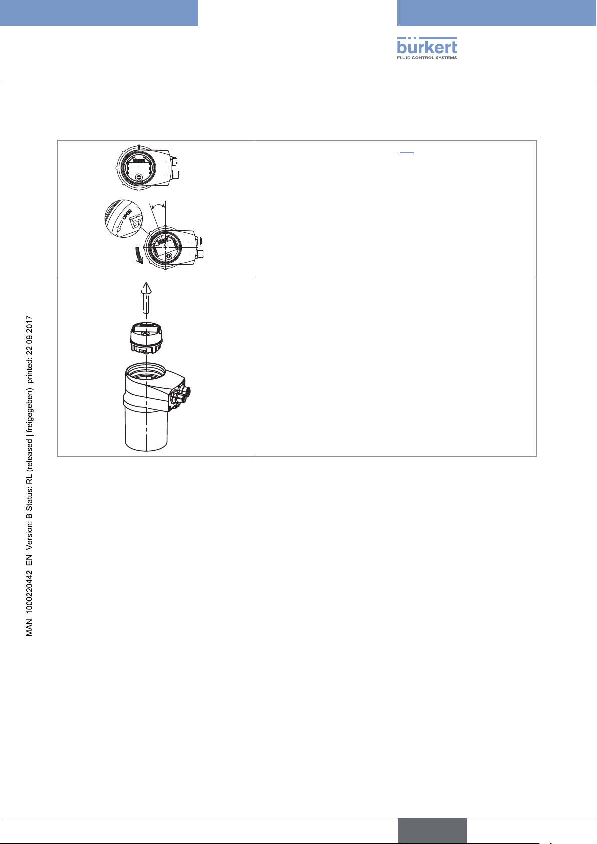
7.2 Removing the cover
NOTE
The tightness of the device is not guaranteed when the cover is removed.
▶ Once the cover is removed, prevent the projection of liquid inside the housing.
The device may be damaged if a metal component comes into contact with the electronics.
▶ Prevent contact of the electronics with a metal component.
2
1
→ [1] Turn the cover counterclockwise with
an angle of about 15° to unlock it.
→ [2] Remove the cover.
If the cover grips to the housing:
Fig. 4: Removing the cover
→ Use an appropriate tool to unlock the
cover, taking care not to scratch the glass.
→ Insert an apropriate tool into the groove of
the housing.
→ Lever the cover up.
19
English
7.3 Mounting the cover
1
b)
d)
→ Check that there is a seal on the housing and that it is not damaged. Replace
it if necessary.
2
→ Grease the seal if necessary, using a component compatible with the seal
material.
→ [1] Set the cover to ensure that the 4 grooves of the cover match with the 4
pins of the housing.
→ [2] Turn the cover clockwise with an angle of about 15° to lock it.
Fig. 5: Closing the cover
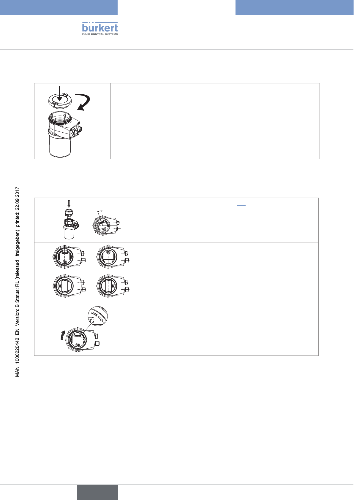
7.4 Mounting the display module
Type 8228
Assembly
20°
a)
Fig. 6: Mounting the display module
→ Remove the cover (see chap. 7.2).
→ Set the display module at an angle of about 20° in relation to
the desired position.
→ The module can be mounted in 4 different positions, at 90°
intervals.
c)
→ Fully push in the module and turn clockwise to lock it.
20
English
Type 8228
Assembly
7.5 Dismounting the display module
→ Remove the cover (see chap. 7.2).
→ Turn the module by ca. 20° counterclockwise.
20°
Fig. 7: Dismounting the display module
Once unlocked, the module is raised slightly by the spring
action.
→ Remove the module from its housing.
English
21
Type 8228
Installation and wiring
8 INSTALLATION AND WIRING
8.1 Safety instructions
Risk of injury due to electrical voltage.
▶ If a 12-36 V DC powered version is installed either in a wet environment or outdoors, all the electrical
voltages must be of max. 35 V DC.
▶ Disconnect the electrical power for all the conductors and isolate it before carrying out work on the system.
▶ All equipment connected to the device shall be double insulated with respect to the mains according to the
standard IEC 61010-1:2010.
▶ Observe all applicable accident protection and safety regulations for electrical equipment.
Risk of injury due to high pressure in the installation.
▶ Stop the circulation of fluid, cut off the pressure and drain the pipe before loosening the process connections.
Risk of injury due to high fluid temperatures.
▶ Use safety gloves to handle the device.
▶ Stop the circulation of fluid and drain the pipe before loosening the process connections.
Risk of injury due to the nature of the fluid.
▶ Respect the regulations on accident prevention and safety relating to the use of aggressive fluids.
WARNING
Risk of injury due to non-conforming installation.
▶ The electrical and fluid installation can only be carried out by qualified and skilled staff with the appropriate
tools.
▶ Install appropriate safety devices (correctly rated fuse and/or circuit-breaker).
▶ Observe mounting instructions of the fitting.
Risk of injury due to unintentional switch on of power supply or uncontrolled restarting of the
installation.
▶ Protect the installation against unintentional power-up.
▶ Guarantee a set or controlled restarting of the process subsequent to any intervention on the device.
22
WARNING
Risk of injury if the fluid pressure/temperature dependency is not respected.
▶ Observe the fluid temperature-pressure dependency according to the material of the conductivity sensor
holder (see the technical data of the device) and according to the materials the fitting is made of (see the
operating instructions of the fitting used).
▶ Observe the pressure equipment directive 97/23/CE.
English
Type 8228
Installation and wiring
Protect this device against electromagnetic interference, ultraviolet rays and, when installed outdoors, the
effects of the climatic conditions.
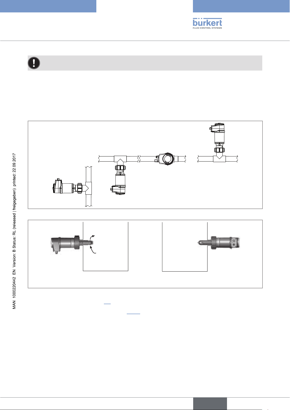
8.2 Installing a 8228 with a G2'' process connection in the pipe
The device is put into a fitting S020 mounted on the pipe.
→ Mount the fitting on the pipe obeying the instructions of the operating instructions of the fitting used.
Fig. 8: Positions for the mounting on the pipe
Tank without mixing device Tank with mixing device
Fig. 9: Positions for the mounting on a container
→ Fit the display module (see chap. 7.4) to calibrate the conductivity sensor and to parameter the device.
→ Calibrate the conductivity sensor (see chap. 9.12.4).
English
23

→ Install the device in the fitting as shown in Fig. 10:
→ Make sure the seal (mark 2) is on the conductivity sensor.
→ Make sure the material of the seal is compatible with the fluid to be
measured.
1
→ Put the nut (mark 5) on the fitting.
→ Put the snap ring (mark 3) into the groove (mark 4).
Type 8228
Installation and wiring
2
→ Screw the nut (mark 5) manually on the device.
→ Engage the device (mark 1) into the fitting.
3
4
5
Fig. 10: Installation of a 8228 with G2'' process connection into the S020 fitting
→ Wire the device according to instructions in chap. 8.4.
8.3 Installing a 8228 with a 2'' clamp process connection in the pipe
DANGER
Risk of injury if the stainless steel adapter of the device is loose.
24
A device with a clamp connection is not tight if the adapter is loose.
▶ Do not loosen the adapter of the device.
The device is installed in a pipe as of DN32.
→ Choose a location on the pipe such as:
- the building of air bubbles is prevented,
- the sensor is completely and continuously immerged in the fluid.
→ Install in the pipe a fitting with a 2'' clamp connection according to ASME BPE for the device.
→ Mount the fitting on the pipe obeying the instructions of the Operating Instructions of the fitting used (not
delivered). Fig. 11 on page 25 shows an example for the fitting (mark 5).
→ Fit the display module (see chap. 7.4) to calibrate the conductivity sensor and to parameter the device.
→ Calibrate the conductivity sensor (see chap. 9.12.4).
English

Type 8228
3
1
2
5
4
Installation and wiring
→ Install the device in the fitting as shown in Fig. 11.
→ Select a seal (mark 4) that is compatible with the 2'' clamp con-
nection of the device and with the fluid.
→ Put the seal (mark 4) on the fitting (mark 5).
→ Insert the device (mark 1) in the fitting (mark 5):
- the electrical connections must be parallel to the pipe,
- the sensor (mark 2) must be positioned in the fluid vein.
→ Tighten the clamp collar (mark 3) by hand.
Fig. 11: Installation of a 8228 with 2'' clamp connection in the pipe
→ Wire the device according to instructions in chap. 8.4.
8.4 Wiring the device
DANGER
Risk of injury due to electrical voltage.
▶ Shut down the electrical power source of all the conductors and isolate it before carrying out work on the
system.
▶ All equipment connected to the device shall be double insulated with respect to the mains according to the
standard IEC 61010-1:2010.
▶ Observe all applicable accident protection and safety regulations for electrical equipment.
• Use a filtered and regulated 12-36 V DC power supply.
• Make sure the installation is equipotential (see chap. 8.4.2).
• Use shielded cables with a temperature limit of 80 °C minimum.
• Do not install the connection cables near high voltage or high frequency cables; If this cannot be
avoided, observe a min. distance of 30 cm.
• Protect the power supply of the device with a 100 mA time-delay fuse and a switch.
• Protect the power supply of each transistor output with a 750 mA fuse.
25
English

Type 8228
5,5
Installation and wiring
8.4.1 Assembling the male or female connector (see chap. "11 Accessories and spare parts")
4 3 2 1
→ Unscrew the nut [1] on the body [4].
→ Insert the cable into the nut [1], the cable clamp [2] and the seal
[3], and then into the body [4].
5
→ Strip 20 mm of the cable.
→ Cut the central wire (earth) so that its length is equal to 11.5 mm.
→ Expose 5.5 mm of the wires on the stripped cable.
5,5
11,5
20
→ Put each wire into the appropriate terminal of the terminal block [5]
(see chap. 8.3.3 or 8.3.4).
→ Tighten the terminal block [5] wired to the body [4].
→ Tighten the connector nut [1].
Fig. 12: Assembling the M12 multi-pin connector (not provided)
8.4.2 Making the installation equipotential
To ensure the equipotentiality of the installation (power supply - device - medium):
→ Connect together the various earth spots in the installation to eliminate the potential differences that may
occur between different earthes.
→ Observe faultless earthing of the shield of the power supply cable, at both ends.
→ If the device is installed on plastic pipes, earth together the metallic instruments such as pumps or valves, that
are as close as possible to the device.
12-36 V DC
+
Metal pipe
Power supply
26
Fig. 13: Equipotentiality skeleton diagram with pipes in metal
English

Type 8228
12-36 V DC
Installation and wiring
12-36 V DC
+
Plastic pipe
Devices such as valves, pumps,...
Fig. 14: Equipotentiality skeleton diagram with pipes in plastic
Power supply
8.4.3 Wiring a version with a single M12 fixed connector
Transistor output (TR1)
2
0V
3
4
Current output (AC1)
Fig. 15: Pin assignment of the male fixed connector on a version with a single M12 fixed connector
Pin of the M12 female cable available as an accessory (order code 438680) Colour of the wire
1 brown
2 white
3 blue
4 black
5
V+ (12-36 V DC)
1
grey
Load
blue
white
2
3
4
brown
1
grey
+ -
Power supply
Fig. 16: NPN wiring of the transistor output of a version with 1 fixed connector (parameter setting "NPN/sink")
English
27

Type 8228
12-36 V DC
Installation and wiring
Load
blue
white
2
3
4
brown
1
grey
+ -
Power supply
Fig. 17: PNP wiring of the transistor output of a version with 1 fixed connector (parameter setting "PNP/source")
4-20 mA input at external
instrument
+-
black
2
brown
3
1
4
grey
blue
+ -
Power supply
12-36 V DC
Fig. 18: Wiring in sinking mode of the current output of a version with 1 fixed connector (parameter setting "NPN/sink")
4-20 mA input at external
instrument
+-
black
2
brown
3
1
4
blue
grey
+ -
Power supply
12-36 V DC
Fig. 19: Wiring in sourcing mode of the current output of a version with 1 fixed connector (parameter setting "PNP/
source")
28
English

Type 8228
12-36 V DC
12-36 V DC
Installation and wiring
Load
white
blue
2
3
black
4
brown
1
grey
4-20 mA input at external
+ -
instrument
Fig. 20: NPN wiring of the transistor output and and wiring in sinking mode of the current output of a version with 1 fixed
connector (parameter setting "NPN/sink")
+ -
Power supply
Load
white
2
4
brown
1
3
blue
grey
black
4-20 mA input at external
+ -
instrument
Fig. 21: PNP wiring of the transistor output and and wiring in sourcing mode of the current output of a version with 1 fixed
connector (parameter setting "PNP/source")
+ -
Power supply
English
29

Type 8228
Installation and wiring
8.4.4 Wiring a version with 2 M12 fixed connectors
Transistor output 1 (TR1)
2
0V
3
1
V+ (12-36 V DC)
4
V+ (12-36 V DC)
Current output 1 (AC1)
Male fixed connector
Fig. 22: Pin assignment of the male and female M12 fixed connectors
Female fixed connector
Transistor output 2 (TR2)
2
1
3
4
Current output 2 (AC2)
Connect the power supply for the device to the male fixed connector; the supply is then
transferred internally to pins 1 and 3 of the female fixed connector in order to ease wiring of the
load to the female fixed connector.
Pin of the female or male M12 cables available as accessories
(order code 438680 respectively 559177)
Colour of the wire
1 brown
2 white
3 blue
4 black
5
0V
grey
Load 1
blue
white
2
3
4
brown
1
white
1
4
2
3
brown
Load 2
grey
+ -
Power supply
12-36 V DC
Fig. 23: NPN wiring of both transistor outputs of a version with 2 M12 fixed connectors (parameter setting "NPN/sink")
Load 1
blue
white
3
white
2
brown
1
4
2
1
3
blue
4
Load 2
grey
+ -
Power supply
12-36 V DC
30
Fig. 24: PNP wiring of both transistor outputs of a version with 2 M12 fixed connectors (parameter setting "PNP/source")
English

Type 8228
Installation and wiring
st
1
4-20 mA input at exter-
nal instrument
+ - + -
2
brown
3
1
4
black
grey
2
instrument
brown
black
nd
4-20 mA input at external
2
3
1
4
blue
Power supply
Fig. 25: Wiring of both current outputs in sinking mode, on a version with 2 fixed connectors (parameter setting "NPN/
sink")
st
4-20 mA input at
1
external instrument
+ -+ -
black
blue
2
brown
3
1
4
12-36 V DC
+ -
12-36 V DC
1
4
grey
+ -
Power supply
nd
4-20 mA input at
2
external instrument
2
blue
3
black
Fig. 26: Wiring of both current outputs in sourcing mode, on a version with 2 fixed connectors (parameter setting "PNP/
source")
4
Load 2
white
2
3
Load 1
blue
white
2
3
4
brown
1
brown
1
black
black
grey
st
1
4-20 mA input at
external instrument
+ - + -
+ -
12-36 V DC
nd
4-20 mA input at
2
external instrument
Power supply
Fig. 27: NPN wiring of both transistor outputs and wiring of both current outputs in sinking mode, on a version with 2 fixed
connectors (parameter setting "NPN/sink")
English
31

Type 8228
Installation and wiring
Load 1
Load 2
white
white
blue
black
2
brown
3
1
4
2
blue
3
1
4
black
grey
st
4-20 mA input at
1
external instrument
+ - + -
+ -
12-36 V DC
nd
2
4-20 mA input at
external instrument
Power supply
Fig. 28: PNP wiring of both transistor outputs and wiring of both current outputs in sourcing mode, on a version with 2
fixed connectors (parameter setting "PNP/source")
32
English

Type 8228
Operating and commissioning
9 OPERATING AND COMMISSIONING
• The settings can only be done on a device with a display module.
• Do not remove the display module while making the settings on the device.
9.1 Safety instructions
WARNING
Risk of injury due to non-conforming operating.
Non-conforming operating could lead to injuries and damage the device and its surroundings.
▶ The operators in charge of operating must have read and understood the contents of this manual.
▶ In particular, observe the safety recommendations and intended use.
▶ The device/installation must only be operated by suitably trained staff.
WARNING
Danger due to non-conforming commissioning.
Non-conforming commissioning could lead to injuries and damage the device and its surroundings.
▶ Before commissioning the device, calibrate the conductivity sensor (see chap. 9.12.4).
▶ Before commissioning, make sure that the staff in charge have read and fully understood the contents of the
manual.
▶ In particular, observe the safety recommendations and intended use.
▶ The device / the installation must only be commissioned by suitably trained staff.
▶ Set the correction factor of the fitting used (see chap. 9.12.4).
9.2 Knowing the operating levels
The device has 2 operating levels:
Process level
This level is used:
• to read the measured values of 2 measurable variables selected in the Parameters menu,
• to read both the lowest and highest values of the chosen measurable variable, that have been measured by the
device since the power-up of the device or since the latest reset (this feature is not active by default),
• to reset both the lowest and highest values of the chosen process value, if the feature has been activated,
• to read the current values emitted on the 4-20 mA outputs,
• to get the state of the device and the conductivity sensor with the icons.
English
33

Configuration level
This level comprises 5 menus:
Menu title Relevant icon
"Param": see chap. 9.11
This is
when the
device is being parame-
tered............
....................
"Calib": see chap. 9.12
"Diagnostic": see chap. 9.13
"Test": see chap. 9.14
"Info": see chap. 9.15
Type 8228
Operating and commissioning
9.3 Using the navigation button
Symbolised by
Symbolised by in
this manual
Symbolised by in this
manual
Fig. 29: Using the navigation button
manual
manual
in this
Symbolised by in this
manual
Symbolised by in this
34
You want to... Press...
...browse in the Process level
• next screen:
• previous screen:
English

Type 8228
Operating and commissioning
You want to... Press...
• ...access the Settings level
• ...display the Param menu
...browse in the menus of the Settings level
...access the menu displayed
...browse in the menu functions
...select the highlighted function
...browse in the dynamic functions bar (MEAS, BACK,
ABORT, OK, YES, NO)
...confirm the highlighted dynamic function
for at least 2 sec., from any screen of the Process
level
• next menu:
• previous menu:
• next function:
• previous function:
• next function:
• previous function:
...modify a numerical value
- increment the figure selected
- decrement the figure selected
- select the previous figure
- select the next figure
- allocate the "+" or "-" sign to the numerical value
- move the decimal point
-
-
-
-
-
-
to the extreme left of the numerical value
then
until the desired sign is displayed
to the extreme right of the numerical value
then
until the decimal point is in the desired
place
English
35

Type 8228
Operating and commissioning
9.4 Using the dynamic functions
You want to... Choose...
...go back to the Process level, without confirming the modifications made
...validate the input dynamic function "OK"
...go back to the parent menu dynamic function "BACK"
... abort the current operation and go back to the parent menu dynamic function "ABORT"
...answer the question asked dynamic function "YES" or "NO"
dynamic function "MEAS"
9.5 Entering a numerical value (example)
Modify each digit of the numerical value using:
Select the digit at
the extreme left of
the numerical value
with
allocate the "+" or
"-" sign to the nu-
merical value with
then
to increase the digit selected,
-
to decrease the digit selected.
-
Calib.Temp
Select the digit at the extreme
+0.000°C
MEAS ABORT OK
.
Dynamic functions (accessible through and ): See chap. 9.4.
right of the numerical value with
then move the decimal point
with
.
36
English

Type 8228
Operating and commissioning
9.6 Browsing in a menu (example)
The icon identifies the current
menu
This is
when the
device is being parame-
tered............
Param
....................
Line1
Highlighted
function
Line2
Contrast
Title of the current menu, sub-menu or
function.
The arrow indicates that some more
functions are available which can be
displayed by using
The arrow indicates that some more
functions are available which can be
MEAS ABORT OK
displayed by using
Dynamic functions (accessible through and ): See chap. 9.4.
9.7 Knowing the display
The display module is only equipped on some versions of the device. It can be ordered as an accessory.
9.7.1 Knowing the icons and LEDs
N
E
P
O
CondS
0.000µS/cm
TempC
Red LED:
shows an error.
See chap. 10.3
Yellow LED: shows that transis-
tor 1 is switched
ERR
Fig. 30: Position of the symbols and description of the LEDs with or without display module
The LEDs of the display module are duplicated on the electronic board that is located under the display
module: these LEDs can only be seen if the device has no display module.
L
O
C
K
23.8 °C
not used
Yellow LED: shows that transistor 2
is switched
Yellow LED: shows that
transistor 1 is switched
Yellow LED: shows that
transistor 2 is switched
Green LED: shows that
the device is energized
Red LED: shows an error.
See chap. 10.3
English
37

Icon Meaning and alternatives
T
Sensor in good condition, fluid conductivity and fluid temperature within the set ranges.
If the monitoring of the conductivity and/or the fluid temperature and/or the fluid conductivity has
been activated, the alternative icons in this position are:
•
, associated with : see chap. 9.13.2, chap. 9.13.3, chap. 9.15.1, chap. 10.3
Type 8228
Operating and commissioning
, associated with
•
ERR
: see chap. 9.13.2, chap. 9.13.3, chap. 9.15.1, chap. 10.3
The device is measuring. The alternative icons in this position are:
!
HOLD
flashing: function HOLD is active (see chap. 9.12.1)
•
•
: running check that the outputs are working and behaving correctly (see chap. 9.14.2 and
chap. 9.14.3)
"maintenance" message; See chap. 9.12.4, chap. 9.15.1, chap. 10.3
"warning" message; See chap. 9.11.10, chap. 9.13.2, chap. 9.13.3, chap. 9.15.1, chap. 10.3
ERR
"error" message; See chap. 9.11.9, chap. 9.13.2, chap. 9.13.3, chap. 9.15.1, chap. 10.3
9.7.2 Knowing the display at the power-up of the device
When the device is powered up or the display module mounted on the electronic module, the display indicates
the software version of the display module. The display then shows the first screen of the Process level:
N
E
P
O
CondS
0.000µS/cm
TempC
L
O
C
23.8 °C
K
See chap. 9.11.5 and 9.11.6 to choose the data to be displayed
in the Process level.
Fig. 31: Display indications after power-up of the device
38
English

Type 8228
Operating and commissioning
9.8 Knowing the Process level
A
First view of the
Process level.
Zoom on the value
in the first line.
Zoom on the value in
the second line.
Display of the highest and
lowest values of the process
value chosen
CondS
1.423 mS/cm
TempC
CondS
1.423
TempC
55
Max
1.450 mS/cm
Min
1.200 mS/cm
55 °C
1)
1)
mS/
1)
°C
2)
Reset Yes/No
B
Display of the cur-
rent outputs.
Zoom on the
value of the first
current output.
Zoom on the value of the second
current output.
AC1
AC2
AC1
18.3 mA
7.5 mA
18.3 mA
AC2
7.5 mA
A
B
1)
To choose the measurable variables to be displayed, see chap. 9.11.5.
2)
The display of the lowest and highest values in the Process level is deactivated by default. To activate the feature and
choose the measurable variables, see chap. 9.11.6.
English
39

9.9 Accessing the Configuration level
Type 8228
Operating and commissioning
Any view of the
Process level
> 2s
This is
when the
This is
when the
device is be-
device is be-
ing parame-
tered............
....................
ing parame-
tered............
....................
Param
Parameters Menu
This is
when the
device is being parame-
tered............
....................
Calib
Calibration Menu
This is
when the
device is being parame-
tered............
....................
Diagnostic
Diagnostic Menu
Wrong
code
Code
"Param"
1)
OK
Code
"Calib"
1)
OK
Code
"Diagnostic"
1)
OK
This is
when the
device is being parame-
tered............
Param
....................
System
Display
Outputs
MEAS BACK
This is
when the
device is being parame-
tered............
Param
....................
Display
Outputs
Sensor
MEAS BACK
Calibration
System
Outputs
Sensor
MEAS BACK
Diagnostic
System
Sensor
MEAS BACK
Test
System
Outputs
Sensor
MEAS BACK
Test Menu
Test
Code
"Test"
OK
1)
Info
Error
Info
Information Menu
1)
Only if the access code to the menu has been customized. See chap. 9.11.3, 9.12.2, 9.13.1 and 9.14.1.
Warning
Maintenance
MEAS BACK
Info
Smiley
Software
Product
MEAS BACK
→ See chap. 9.10 for the detailed menu functions
40
English

Type 8228
Operating and commissioning
9.10 Knowing the structure of the menus of the Configuration level
See chap. 9.9 to access the Configuration level.
Param
This is
when the
device is being parame-
tered............
....................
System
This is
when the
device is being parame-
tered............
....................
Up/Download Download
Upload
Date
Time
Code
Factory reset
YYYY/MM/DD
HH:MM
0*** Confirm code 0***
Reset Yes/No
Downl. Yes/No
Upload Yes/No
ss
If an "upload" has been succesfully made with
this module
Display
This is
when the
device is being parame-
tered............
....................
Line1 / Line2:
PVar:
Unit:
Filter:
Min/Max: EnabledStatus:
PVar:
Unit:
Contrast
Backlight
xx %
xx %
EnabledLine1 / Line2:
Disabled
CondS
CondR
TempC
TempF
TDSppm
µS/cm
mS/cm
W.cm
kW.cm
W.cm
M
°F
°C
ppm
None
Fast
Slow
Disabled
CondS
CondR
TempC
TempF
TDSppm
µS/cm
mS/cm
W.cm
kW.cm
W.cm
M
°F
°C
ppm
If PVar = "CondS"
If PVar = "CondS"
If PVar = "CondR"
If PVar = "CondR"
If PVar = "CondR"
If PVar = "TempF"
If PVar = "TempC"
If PVar = "TDSppm"
If PVar = "CondS"
If PVar = "CondS"
If PVar = "CondR"
If PVar = "CondR"
If PVar = "CondR"
If PVar = "TempF"
If PVar = "TempC"
If PVar = "TDSppm"
English
41

Type 8228
Operating and commissioning
Param
This is
when the
device is being parame-
tered............
....................
Outputs HWMode sink/NPN
This is
when the
device is being parame-
tered............
....................
AC1/AC2
source/PNP
PVar:
4mA:
20mA:
Filter:
Mode diag. None
TR1 / TR2
PVar:
CondS
CondR
TempC
TempF
TDSppm
INPUT
INPUT
None
Fast
Slow
22mA
CondS
CondR
TempC
TempF
TDSppm
warning
Sensor
This is
when the
device is being parame-
tered............
....................
Calib System Hold
Code 0*** Confirm code 0***
Outputs AC1/AC2
Mode:
Low:
High:
Contact:
Delay:
NoneComp.:
Linear:0.000%
NaCl
NaOH
HNO3
H2SO4:
Special
Hold:Disabled
Hold:Enabled
4mA
20mA
Hysteresis
Window
INPUT
INPUT
Normally open
Normal. closed
INPUT
INPUT
INPUT
INPUT
≠ "warning"
If PVar
If PVar ≠ "warning"
≠ "warning"
If PVar
42
English

Type 8228
Operating and commissioning
Calib
Diagnostic System
Sensor Probe
Zero Calib.
Calibration INPUT
Cell constant
K-fitting INPUT
Cell cst. TDS
Calib interval
Teach special
Temperature INPUT
Code 0*** Confirm code 0***
Calibrate Zero
Point?
Processing
INPUT
INPUT
Last cal. date
Interval
Start temp
INPUT
Stop temp
INPUT
Processing
RESULT
READ
INPUT
ConductivitySensor
Temperature
Activate: Yes/No
Conductivity
Warn hi: INPUT
Warn lo: INPUT
Err hi: INPUT
Err lo: INPUT
Activate: Yes/No
Temperature
Warn hi: INPUT
Warn lo: INPUT
Err hi: INPUT
Err lo: INPUT
READ
READ
English
43

Type 8228
Operating and commissioning
Test
Info Error
System
Outputs
Sensor
Software
Code 0*** Confirm code
AC1: INPUT
AC2:
TR1: OFF/ON
TR2: OFF/ON
PVar:
Value:
MESSAGE
MESSAGEWarning
MESSAGEMainten.
MESSAGESmiley
Main
Sensor
INPUT
CondS
CondR
TempC
TempF
TDSppm
INPUT
READ
READ
0***
Product READ
44
English

Type 8228
Operating and commissioning
9.11 Knowing the Parameters menu
9.11.1 Transferring data from one device to another
See chap. 9.9 to access the Parameters menu.
This function is only possible with a display module with software version V2.
→ On the device, check the software version in the menu "Info -> Software -> Main".
• The software version of the display module is displayed when the display module is powered up.
• Function "DOWNLOAD" is only present if an "UPLOAD" has been successfully carried out.
• Never interrupt a data transfer else the device could be damaged.
The compensation curve determined with the function TEACH SPECIAL (see chap. 9.12.4) cannot be
transferred to another device.
This is
when the
device is being parame-
tered............
....................
SystemParam
This is
when the
device is being parame-
tered............
....................
Up/Download Download
Upload
Downl. Yes/No
Upload Yes/No
The following data can be transferred from a device to another device of the same type:
• user set data of the PARAM menu (except the date, the time, the contrast and brightness levels for the display),
• user set data of the DIAGNOSTIC menu,
• the TDS factor set in the menu Calib -> Sensor -> Probe -> Cell cst TDS,
• the correction factor set in the menu Calib -> Sensor -> Probe -> K-fitting,
• the periodicity of calibrations set in the menu Calib -> Sensor -> Probe -> Calib interval,
• the access codes to the menus.
DOWNLOAD: transfer the data previously uploaded in the display module with the "UPLOAD" function.
The parameters transferred are used by the device as soon as the message “Download OK” is displayed.
UPLOAD: upload data from the device to the display module.
9.11.2 Setting the date and time
See chap. 9.9 to access the Parameters menu.
Param YYYY/MM/DD
This is
when the
device is being parame-
tered............
....................
DAT E: set the date (input format: year/month/day in the form YYYY/MM/DD)
TIME: set the time (input format: hours:minutes
System Date
This is
when the
device is being parame-
tered............
....................
Time
HH:MM
secondes
ss
)
45
English

Type 8228
Operating and commissioning
9.11.3 Modifying the PARAM menu access code
See chap. 9.9 to access the Parameters menu.
Param
This is
when the
device is being parame-
tered............
....................
System
This is
when the
device is being parame-
tered............
....................
Code
0*** Confirm code 0***
Enter the new
code
Enter the new code a
second time
If the default code (0000) is entered, the code will not be requested to access the menu.
9.11.4 Restoring the default parameters of the Process level and
the outputs
See chap. 9.9 to access the Parameters menu.
The following data can be restored to their default values:
• user set data of the PARAM menu (except the date, the time, the contrast and brightness levels for the display),
• user set data of the DIAGNOSTIC menu,
• the TDS factor set in the menu Calib -> Sensor -> Probe -> Cell cst TDS,
• the correction factor set in the menu Calib -> Sensor -> Probe -> K-fitting,
• the periodicity of calibrations set in the menu Calib -> Sensor -> Probe -> Calib interval,
• the access codes to the menus.
Reset Yes/No
This is
when the
device is being parame-
tered............
....................
SystemParam
This is
when the
device is being parame-
tered............
....................
Factory Set
Execute
→ Choose “Yes” to restore the default values.
→ Choose “No” to keep the set values.
46
English

Type 8228
6 s
40 s
t
Operating and commissioning
9.11.5 Setting the data displayed in the Process level
See chap. 9.9 to access the Parameters menu.
Param
This is
when the
device is being parame-
tered............
....................
Display
This is
when the
device is being parame-
tered............
....................
PVar:
EnabledLine1 / Line2:
Disabled
CondS
CondR
TempC
TempF
TDSppm
Unit:
Filter:
µS/cm
mS/cm
W.cm
kW.cm
W.cm
M
°F
°C
ppm
None
If PVar = "CondS"
If PVar = "CondS"
If PVar = "CondR"
If PVar = "CondR"
If PVar = "CondR"
If PVar = "TempF"
If PVar = "TempC"
If PVar = "TDSppm"
Fast
Slow
PVAR: choose the process value to be displayed on the line selected.
UNIT: choose the unit for the process value displayed.
FILTER: choose the filter level for the measurement values displayed on the line selected. Three filter levels are
proposed: “slow”, “fast” or “none”.
"slow" "fast" "none"
t
Fig. 32: Filter curves
3 s (conductivity measurement)
t
280 s (temperature measurement)
47
English

Type 8228
Operating and commissioning
9.11.6 Displaying of the lowest and highest values measured
See chap. 9.9 to access the Parameters menu.
Param
This is
when the
device is being parame-
tered............
....................
Display
This is
when the
device is being parame-
tered............
....................
Min/Max: EnabledStatus:
PVar:
Disabled
CondS
CondR
TempC
TempF
TDSppm
Unit:
µS/cm
mS/cm
W.cm
kW.cm
W.cm
M
°F
°C
ppm
If PVar = "CondS"
If PVar = "CondS"
If PVar = "CondR"
If PVar = "CondR"
If PVar = "CondR"
If PVar = "TempF"
If PVar = "TempC"
If PVar = "TDSppm"
STATUS: choose to display (choice “Enabled”) or not display (choice “Disabled”) the highest and lowest measured
values (of the measurable variable chosen in PVAR hereafter) since the latest reset or the power-up of the device.
PVAR: choose the measurable variable which highest and lowest measured values are displayed in the Process level.
UNIT: choose the preferred unit in which the lowest and highest measured values are displayed.
9.11.7 Setting the display contrast and brightness
48
See chap. 9.9 to access the Parameters menu.
Param
This is
when the
device is being parame-
tered............
....................
Display
This is
when the
device is being parame-
tered............
....................
Contrast xx %
Backlight xx %
→ Set each percentage using and .
CONTRAST: choose the display contrast level (as a %).
BACKLIGHT: choose the light intensity of the display (as a %).
These settings only affect the display module. They are not factored in during a device data UPLOAD (see
chap. 9.11.1).
English

Type 8228
Operating and commissioning
9.11.8 Choosing the output wiring mode
See chap. 9.9 to access the Parameters menu.
Param
This is
when the
device is being parame-
tered............
....................
Outputs
This is
when the
device is being parame-
tered............
....................
HWMode
source/PNP
sink/NPN
The wiring mode is the same for all outputs.
→ If "sink/ NPN" is set, wire the current outputs in sinking mode and the transistor outputs in NPN.
→ If "source/ PNP" is set, wire the current outputs in sourcing mode and the transistor outputs in PNP.
See chap. "8.4 Wiring the device".
9.11.9 Setting the parameters of the current outputs
See chap. 9.9 to access the Parameters menu.
The 2nd current output “AC2” is only available on a version with 2 fixed connectors.
Param
This is
when the
device is being parame-
tered............
....................
Outputs
This is
when the
device is being parame-
tered............
....................
AC1 / AC2
PVar:
4mA:
20mA:
Filter:
CondS
CondR
TempC
TempF
TDSppm
INPUT
INPUT
Slow
Fast
None
Mode diag. None
22mA
PVAR: choose a process value (impedance in W.cm, conductivity in S/cm, temperature in °C, temperature in °F or
total dissolved solids in ppm) associated with current output 1 resp. current output 2.
49
English

Type 8228
mA
20
Operating and commissioning
Functions “4mA” and “20mA” are used to define the measurement range for the process value associated with
the current on the 4-20 mA output.
P1 and P2 are the values associated with a current of 4 mA or 20 mA respectively:
is higher than P2, the signal is inverted and the range P1-P2 corresponds to the range for the 20-4 mA
If P
1
current.
4
0
P
1
Process value chosen
P
2
Fig. 33: 4-20 mA current depending on the process value selected
4mA: choose the value of the process value (previously selected), associated with a current of 4 mA, for each
current output.
50
20mA: choose the value of the process value (previously selected), associated with a current of 20 mA, for each
current output.
FILTER: choose the level of damping for the fluctuations of the current value for each current output. Three filter
levels are proposed: slow, fast or none. The damping for the current outputs is similar to the damping of the
display (see Fig. 32, chap. 9.11.5).
MODE DIAG.: choose to emit a current of 22 mA on the current output selected when an “error” event related to
diagnostics (see chap. 9.13.2 and 9.13.3) is generated by the device or allow the current output to operate normally (choose "none").
An "error" event linked to a malfunction of the device is always indicated by the generation of a 22 mA
current, whatever the adjustmant made in the function "MODE DIAG.".
See also chap. "10.3 Solving a problem".
9.11.10 Setting the parameters of the transistor outputs
See chap. 9.9 to access the Parameters menu.
Param
This is
when the
device is being parame-
tered............
....................
Outputs
This is
when the
device is being parame-
tered............
....................
TR1 / TR2
PVar:
Mode: Hysteresis
Low:
High:
Contact:
Delay: INPUT
CondS
CondR
TempC
TempF
TDSppm
Warning
Window
INPUT
INPUT
Normally open
Normally closed
≠ "warning"
If PVar
If PVar ≠ "warning"
≠ "warning"
If PVar
English

Type 8228
ON
OFF
ON
OFF
ON
OFF
ON
OFF
Operating and commissioning
PVAR: choose a measurable variable (impedance in W.cm, conductivity in S/cm, temperature in °C, temperature
in °F or total dissolved solids in ppm) associated with transistor output 1 resp. transistor output 2 or associate
the “warning” message (see chap. 9.12.4, chap. 9.13.2 and chap. 9.13.3) with transistor output 1 resp. transistor
output 2.
If the selected transistor output is linked to the "warning" event, the transistor switches as soon as such an event
is generated by the device.
See also chap. "10.3 Solving a problem".
MODE: choose the operating, hysteresis or window, for transistor output 1 or transistor output 2 (see Fig. 34 and
Fig. 35).
LOW: enter the low switching threshold value for transistor output 1 or transistor output 2 (see Fig. 34 and
Fig. 35).
HIGH: enter the high switching threshold value for transistor output 1 or transistor output 2(see Fig. 34 and
Fig. 35).
CONTACT: choose the type of off-position (normally open, NO, or normally closed, NC) of transistor output 1 or
transistor output 2 (see Fig. 34 and Fig. 35).
DELAY: choose the value of the time delay prior to switching, for each transistor output.
Switching only occurs if one of the thresholds, high or low (functions “High” or “Low”), is exceeded for a duration
longer than this time delay (see Fig. 34 and Fig. 35). The time delay before switching is applicable to both output
thresholds.
Hysteresis operating
The change of status is done when a threshold is detected (increasing measured value: threshold high (function
High) to be detected; decreasing measured value: threshold low (function Low) to be detected).
NO = normally open NC = normally closed
contact
process value
Low High
Fig. 34: Hysteresis operating
contact
process value
Low High
Window operating
The change of status occurs whenever one of the thresholds is detected.
NO = normally open NC = normally closed
contact
contact
Low High
Fig. 35: Window operating
process value
process value
Low High
51
English

Type 8228
T
Operating and commissioning
9.11.11 Choosing the type of temperature compensation
See chap. 9.9 to access the Parameters menu.
This menu is used to deactivate the temperature compensation (choice “none”) or choose the type of temperature
compensation to determine the conductivity of the fluid:
• according to a linear percentage (choice “linear”, see "Linear temperature compensation (choice “Linear”)",
page 52).
• or according to a predefined curve (choix "NaCl", "NaOH", "HNO
" or "H2SO4").
3
The compensation curve H2SO4 applies to a fluid temperature range of 5-55 °C and a concentration of 20,0%:
The compensation curves for NaOH, HNO3 and NaCI apply to a fluid temperature range of 10-80°C and for
the following concentrations:
- NaCl: 0,2 %
- NaOH: 1,0 %
- HNO
: 1,0 %
3
• or according to a curve defined especially for your process (choice “Special”) using the “Teach special”
function in the “Calibration - Sensor” menu, “Probe” function (see chap. 9.12.4).
If the choice "Special" is set for this function:
• and the compensation curve has not been determined (see chap. 9.12.4), the measurements of the
conductivity are not compensated in temperature.
• If the compensation curve has been determined (see chap. 9.12.4), it is not uploaded with the
function UPLOAD (see chap. 9.11.1).
Param
This is
when the
device is being parame-
tered............
....................
Sensor
This is
when the
device is being parame-
tered............
....................
NoneComp.:
Linear:0.000%
NaCl
NaOH
HNO3
H2SO4:
Special
INPUT
52
Linear temperature compensation (choice “Linear”)
The linear temperature compensation may be sufficiently precise for your process whenever the temperature of
your process is always > 0°C. Enter a compensation value (average compensation coefficient alpha) between
0.00 and 10.00 %/°C.
Use the following curve and equation to calculate the average value of the compensation coefficient a according
to a temperature range DT and the associated conductivity range Dc:
χ
χ
T
∆χ
χ
25
25
∆T
T [°C]
α =
∆χ
∆T
1
x
χ
25
English

Type 8228
Operating and commissioning
9.12 Knowing the Calibration menu
9.12.1 Activating/deactivating the Hold function
See chap. 9.9 to access the Calibration menu.
Calib System Hold
If the mode "Hold" is activated and if there is a power interruption, then, when the device restarts, the
mode "Hold" is automatically deactivated.
The mode "Hold" is used to carry out maintenance work without interrupting the process.
To activate the mode HOLD:
→ access the "HOLD" function;
Hold:Disable
Hold:Enable
→ choose "enabled" and confirm by "OK".
To deactivate the mode HOLD:
→ access the "HOLD" function;
→ choose "disabled" and confirm by "OK".
In practice, when the device is in mode "Hold":
• the
!
icon is displayed in place of the icon;
HOLD
• the current emitted on each 4-20 mA output is fixed at the value of the last measurement of the physical
parameter associated with each output;
• each transistor output is fixed at the status acquired at the moment the Hold function is activated;
• the device is in Hold mode until the HOLD function is deactivated.
9.12.2 Modifying the Calibration menu access code
See chap. 9.9 to access the Calibration menu.
Code 0*** Confirm code 0***Calib System
Enter the new
code
Enter the new code
a second time
If the default code (0000) is entered, the code will not be requested to access the menu.
English
53

9.12.3 Adjusting the current outputs
See chap. 9.9 to access the Calibration menu.
Type 8228
Operating and commissioning
Calib
Outputs AC1 / AC2
4mA:
20mA:
INPUT
INPUT
4mA: adjust the current output 1 or current output 2 for 4 mA.
When the "4mA" function is selected, the device generates a current of 4 mA: measure the current emitted by
the 4-20 mA output using a multimeter and enter the value given by the multimeter in the function “AC1.4mA” or
“AC2.4mA”.
20mA: adjust the current output 1 or current output 2. for 20 mA
When the "20mA" function is selected, the device generates a current of 20 mA: measure the current emitted by
the 4-20 mA output using a multimeter and enter the value given by the multimeter in the function “AC1.20mA” or
“AC2.20mA”.
9.12.4 Calibrating the sensor
DANGER
Risk of injury due to electrical voltage.
▶ Observe all applicable accident protection and safety regulations for electrical equipment.
Risk of injury due to the nature of the fluid.
▶ Respect the regulations on accident prevention and safety relating to the use of aggressive fluids.
See chap. 9.9 to access the Calibration menu.
Calib Sensor Probe
Zero Calib.
Calibration INPUT
Cell constant
K-fitting INPUT
Cell cst. TDS
Calib interval
Teach special
Calibrate Zero
Point?
Processing
INPUT
INPUT
Last cal. date
Interval
Start temp
INPUT
Stop temp
INPUT
Processing
RESULT
READ
INPUT
54
English

Type 8228
Operating and commissioning
The accuracy of the conductivity measurements is influenced by:
• the drift of the zero point of conductivity. Correct the drift of the zero point with the function ZERO CALIB. To
be done if the conductivity of the air measured by the conductivity sensor is higher than 10 µS/cm (see "Calibrate the zero point of conductivity (function "Zero Calib." of the menu "Probe")", page 56).
• the conductivity cell constant:
- determine the cell constant of the sensor used with the function CALIBRATION (this calibration updates the
last calibration date in the “Last cal. date” function of the CALIB INTERVAL sub-menu hereafter). See "Calibrate the conductivity sensor (“Calibration” function in the “Probe” menu)", page 57,
- or enter the cell constant (marked on the calibration certificate of the device) in the function CELL CONSTANT. The entering of the cell constant does not update the last calibration date in the “Last cal. date”
function of the CALIB INTERVAL sub-menu. The function CELL CONSTANT makes it also possible to read
the value of the constant which has been determined with the function CALIBRATION.
• the correction factor of the fitting. Enter the correction factor related to the fitting S020 used in the function
K-FITTING. The correction factor depends on the shape, the material and the diameter of the fitting used. The
following table gives the correction factors of the fittings S020.
Tab. 1: Correction factors of the fittings S020, depending on the shape, the material and the DN of the fittings
Fittings with true union
connections or fittings with
weld ends
Fittings with internal or
external thread connections
or fittings with weld end
Measurement
chamber Welding sockets or fusion
spigots
connections
PVDF PP PVC Brass Stainless steel
DN
Stainless
steel
PVDF PP
<32 1,08 1,08 1,08 0,99 0,99 - - - -
32 1,08 1,08 1,08 0,99 0,99 0,99 - - 40 1,04 1,04 1,04 0,99 0,99 0,99 - - 50 1,02 1,02 1,02 0,99 0,99 0,99 0,99 - 65 - - - - - - 0,99 1,02 1,02
80 - - - - - - 0,99 1,02 1,02
100 - - - - - - 1,00 1,02 1,02
>100 - - - - - - 1,00 1,00 1,00
CELL CST TDS: enter the TDS factor suited to your process. The TDS factor allows for calculating the amount
of Total Dissolved Solids (TDS), in ppm, depending on the measured conductivity. The default TDS factor is 0,46
(NaCl)
CALIB INTERVAL: read the date of the last calibration (function “Last cal. date”) and set the periodicity of calibrations, in days (function “Interval”): the device generates a “maintenance” event by displaying the
icon and a
“warning” message, each time a calibration is due. Set function “Interval” to “0000 days” to ignore the function.
• The "warning" message may be associated with one or other or both transistor outputs (see
chap. 9.11.10).
• See also chap. "10.3 Solving a problem".
TEACH SPECIAL: define the temperature compensation curve specific to your process. The curve thus determined and memorised is used by the device when you choose “Special” in the “Comp.” function in the menu
“Param - Sensor” (see chap. 9.11.11). See also "Define the temperature compensation curve specific to your
process (“Teach special” function in the”Probe” menu)", page 59.
The compensation curve determined with the function TEACH SPECIAL cannot be transferred to another
device with the function DOWNLOAD (see chap. 9.11.1).
English
55

Type 8228
Operating and commissioning
Calibrate the zero point of conductivity (function "Zero Calib." of the menu "Probe")
• In order not to interrupt the process, activate the HOLD function (see chap. 9.12.1).
• Before each calibration, fully clean the conductivity sensor with a special cleaning agent, then rince and
dry.
If the value of air conductivity measured is higher than 10 µS/cm, readjust the device, holding the sensor in the air
(zero point of conductivity of the device).
Calib Sensor Probe Zero Calib.
Calibrate Zero
Point?
→ Put the cleaned and dried conductivity sensor in
contact with the ambient air.
YES
Processing
Save modified
data?
The device automatically calibrates the
zero point of conductivity in less than 1
second.
→ Save or not the calibration result by
choosing "Yes" or "No".
56
English

Type 8228
Operating and commissioning
Calibrate the conductivity sensor (“Calibration” function in the “Probe” menu)
Calibration consists in determining the C constant specific to each conductivity sensor using a solution with a
known conductivity.
• In order not to interrupt the process, activate the HOLD function (see chap. 9.12.1).
• Before each calibration, fully clean the conductivity sensor with a special cleaning agent.
• To calibrate a conductivity sensor off-line, put the sensor in the center of a beaker of min. 8 cm in
diameter.
• To calibrate a conductivity sensor off-line, make sure there are no air bubbles in the hole of the conduc-
tivity sensor.
• Set the periodicity of calibrations in the "Interval" function in the sub-menu "Calib interval" (see
page 55): each time a calibration is due, the device generates a "maintenance" event and a "warning"
event.
English
57

Calib Sensor CalibrationProbe
→ Immerse the clean conductivity sensor in the solution with a known
conductivity. The device alternately displays:
• the measured conductivity of the solution
• the measured temperature of the solution
Calibration
5.023 µS/cm
5.000 µS/cm
OK
Type 8228
Operating and commissioning
→ Enter the conductivity, at
the fluid temperature, of
the reference solution used
(marked on the bottle or
measured using a reference
instrument).
→ Change the unit if necessary.
Probe
"Error: out of
BACK
The message "Error: out of range" signals that the cell
constant is out of the authorized range (< 0,8 or > 12);
This may be due to:
• either a mistake made when entering the conductivity,
• or when there are air bubbles in the hole of the conductivity sensor
• or when the minimum distance of 4 cm between the
conductivity sensor and the sides of the beaker is not
observed.
range"
Cal. Result
+1.00000
OK
Cal. Result
Save: Yes/No
The device displays the calibration
result.
Save or not the calibration result by
choosing "Yes" or "No".
58
English

Type 8228
Operating and commissioning
Define the temperature compensation curve specific to your process (“Teach special” function in
the”Probe” menu)
Calib Sensor Teach specialProbe
Start temp
+40.00°C
→ Enter the value for the start of the temperature range for which the com-
pensation curve must be determined.
OK
Stop temp
+55.00°C
The fluid temperature range (T-; T+) must be entered in such a way that the difference between T- and T+
is greater than 8 °C. The message "Error: Temp span at least 8 °C" is displayed if the difference between
the range start and end values is less than 8 °C.
→ Enter the value of the end of the temperature range for which the compen-
sation curve must be determined.
→ Before confirming to begin the procedure, check that the fluid temperature
is below 25 °C and T-.
OK
Processing...
1.234 mS
When the function HOLD is deactivated (chap. 9.12.1), the device determines the compensation curve with 10
points and alternately displays both the measured conductivity and the measured temperature of the solution.
• Immerse the sensor in the solution and progressively reheat:
- from T- to 25 °C if T- < T+ < 25 °C
- from T- to T+ if T- < 25 °C < T+
- from 25 °C to T+ if 25 °C < T- < T+
• The rise in temperature must be slow because of the inertia of the temperature sensor.
• Avoid the formation of bubbles on the conductivity sensor.
Start temp.
Start temp.
"Error: current
BACK
temp. is too
high"
The message "Error: current temp. is too high"
is displayed if, at the beginning of the TeachIn procedure, the fluid temperature is higher
than 25 °C or than T-.
Cal. Result
Save: Yes/No
At the end of processing,
save the compensation
curve or not.
"Error: temp
span at least
BACK
8°C"
The message "Error: Temp
span at least 8 °C" is displayed
if the difference between the
range start and end values is
less than 8 °C.
English
59

Type 8228
Operating and commissioning
9.12.5 Entering an offset for the temperature measurement
See chap. 9.9 to access the Calibration menu.
The temperature transmitted by the temperature probe may be corrected. This correction value is the temperature
offset.
Calib Sensor Temperature INPUT
Enter the temperature offset
(±5 °C)
9.13 Knowing the Diagnostic menu
9.13.1 Modifying the Diagnostic menu access code
See chap. 9.9 to access the Diagnostic menu.
Code 0*** Confirm code 0***Diagnostic System
Enter the new
code
Enter the new code a
second time
If the default code (0000) is entered, the code will not be requested to access the menu.
9.13.2 Monitoring the fluid conductivity
See chap. 9.9 to access the Diagnostic menu.
The function allows for monitoring the measured value of the fluid conductivity and for configuring the behaviour
of the device if the parametered ranges are exceeded.
A malfunction in your process or the conductivity sensor may be indicated either by too low or too high a
measured fluid conductivity.
Diagnostic
ConductivitySensor
Activate: Yes/No
Conductivity
Warn hi: INPUT
Warn lo: INPUT
Err hi: INPUT
Err lo: INPUT
READ
To be warned when the fluid conductivity is too low or too high:
→ activate monitoring of the fluid conductivity in the function “activate”, then
→ set a conductivity range outside of which the device generates a “warning” event and displays the and
icons.
→ set a conductivity range outside of which the device generates an “error” event and displays the and
icons.
ERR
60
English

Type 8228
Operating and commissioning
When the device generates a "warning" or an "error" event:
→ go into the “Info” menu to read the cause of the event generation.
→ and/or go into the “Sensor” function of the Diagnostic menu to read the measured conductivity value.
→ if necessary, clean and/or recalibrate the conductivity sensor,
→ if necessary, check the process.
• The "warning" event may also be associated with one or both transistor outputs (see chap. 9.11.10, function
"Output.TR1" or "Output.TR2").
• The "error" event may also be associated with one or both current outputs (see chap. 9.11.9, function
"Output.AC1" or "Output.AC2").
• See also chap. "10.3 Solving a problem".
ACTIVATE: choose whether or not to activate monitoring of the fluid conductivity.
CONDUCTIVITY: read the fluid conductivity measured in real time.
WARN HI: enter the fluid conductivity value above which a “warning” event is generated.
WARN LO: enter the fluid conductivity value below which a “warning” event is generated.
ERR HI: enter the fluid conductivity value above which an “error” event is generated.
ERR LO: enter the fluid conductivity value below which an “error” event is generated.
9.13.3 Monitoring the fluid temperature
See chap. 9.9 to access the Diagnostic menu.
The function allows for monitoring the fluid temperature and configure the behaviour of the device if the parametered ranges are exceeded.
A malfunction in your process or the conductivity sensor may be indicated either by too low or too high a
measured fluid temperature.
Diagnostic
Sensor
Temperature
Activate: Yes/No
Temperature
Warn hi: INPUT
Warn lo: INPUT
Err hi: INPUT
Err lo: INPUT
READ
To be warned when the fluid temperature is too low or too high:
→ activate monitoring of the fluid temperature in the function “activate”, then
→ set a temperature range (in °C) outside of which the device generates a “warning” event and displays the
icons.
and
→ set a temperature range (in °C) outside of which the device generates an “error” event and displays the
ERR
and
icons.
English
61

Type 8228
T
Operating and commissioning
When the device generates a "warning" or an "error" event:
→ go into the “Info” menu to read the cause of the event generation.
→ and/or go into the “Sensor” function of the Diagnostic menu to read the measured temperature value.
→ then make sure the built-in temperature probe is working correctly by measuring a fluid with a known temper-
ature. If the temperature probe is faulty, return the device to Bürkert.
→ if the temperature probe is not the cause of the problem, check the process.
• The "warning" event can be associated to one or both transistor outputs (see chap. 9.11.10, function
"Output.TR1" or "Output.TR2").
• The "error" event can be associated to one or both current outputs (see chap. 9.11.9, function "Output.
AC1" or "Output.AC2").
• See also chap. "10.3 Solving a problem".
ACTIVATE: choose whether or not to activate monitoring of the fluid temperature.
TEMPERATURE: read the fluid temperature measured in real time through the built-in temperature probe.
WARN HI: enter the fluid temperature value above which a “warning” event is generated.
WARN LO: enter the fluid temperature value below which a “warning” event is generated.
ERR HI: enter the fluid temperature value above which an “error” event is generated.
ERR LO: enter the fluid temperature value below which an „error“ event is generated.
9.14 Knowing the Test menu
9.14.1 Modifying the Test menu access code
See chap. 9.9 to access the Test menu.
Test
If the default code (0000) is entered, the code will not be requested to access the menu.
9.14.2 Checking the outputs functions
System
Code 0*** Confirm code 0***
Enter the new code Enter the new code a second
time
See chap. 9.9 to access the Test menu.
• Make sure the "Hold" mode is deactivated (see chap. 9.12.1).
• The
icon is displayed in place of the icon as soon as the check for the correct working of an
output has started. During the check the related output does not react according to the measured
physical value.
AC1: INPUT
AC2:
TR1: OFF/ON
TR2: OFF/ON
INPUT
62
Test
Outputs
English

Type 8228
T
Operating and commissioning
AC1: check that current output 1 is working correctly by entering a current value and then selecting “OK”.
AC2: check that current output 2 is working correctly by entering a current value and then selecting “OK”.
TR1: check that transistor output 1 is working correctly by selecting the status of the transistor (“ON” or “OFF”)
then “OK”.
TR2: check that transistor output 2 is working correctly by selecting the status of the transistor (“ON” or “OFF”)
then “OK”.
9.14.3 Checking the outputs behaviour
See chap. 9.9 to access the Test menu.
• Make sure the "Hold" mode is deactivated (see chap. 9.12.1).
• The symbol
is displayed in place of the symbol as soon as a simulation of a measurable variable
has been started. During the check the outputs do not react according to the measured process
variable.
The feature allows for simulating the measurement of the process value to check if the outputs are correctly
configured.
Test
Sensor
PVar:
Value:
CondS
CondR
TempC
TempF
TDSppm
INPUT
PVAR: choose the process value to be tested.
VALUE: enter a process value selected from the “PVAR” function above to check output behaviour.
63
English

Type 8228
Operating and commissioning
9.15 Knowing the Information menu
9.15.1 Reading the cause of events linked to icons
See chap. 9.9 to access the Information menu.
Info Error
Software
Product READ
The function allows for reading a short description of the reason why the following icons are displayed by the
device:
- ERROR:
ERR
- WARNING:
MESSAGE
MESSAGEWarning
MESSAGEMainten.
MESSAGESmiley
Main
Sensor
READ
READ
- MAINTENANCE:
- SMILEY: or
See also chap. "10.3 Solving a problem".
9.15.2 Reading the software versions
See chap. 9.9 to access the Information menu.
Info
Software
Main
Sensor
READ
READ
The function allows for reading:
• the software version of the acquisition / conversion board ("Main") for the measurable variables,
• the software version of the sensor ("Sensor").
9.15.3 Reading some identification informations of the device
See chap. 9.9 to access the Information menu.
Info
Product
READ
64
The function allows for reading some of the informations that are on the name plate of the device:
• the type of the device,
• the serial number,
• the order code.
English

Type 8228
Maintenance and troubleshooting
10 MAINTENANCE AND TROUBLESHOOTING
10.1 Safety instructions
Risk of injury due to electrical voltage.
▶ Shut down the electrical power source of all the conductors and isolate it before carrying out work on the
system.
▶ All equipment connected to the 8619 shall be double insulated with respect to the mains according to the
standard IEC 61010-1:2010.
▶ Observe all applicable accident protection and safety regulations for electrical equipment.
Risk of injury due to high pressure in the installation.
▶ Stop the circulation of fluid, cut off the pressure and drain the pipe before loosening the process connections.
Risk of injury due to high fluid temperatures.
▶ Use safety gloves to handle the device.
▶ Stop the circulation of fluid and drain the pipe before loosening the process connections.
Risk of injury due to the nature of the fluid.
▶ Respect the regulations on accident prevention and safety relating to the use of aggressive fluids.
WARNING
Risk of injury due to non-conforming maintenance.
▶ Maintenance must only be carried out by qualified and skilled staff with the appropriate tools.
▶ Ensure that the restart of the installation is controlled after any interventions.
10.2 Cleaning the device
• If magnetic particles are in the fluid to be measured, often clean the deposits on the conductivity sensor,
with a special cleaning agent.
• Always use a cleaning product compatible with the materials from which the device is made.
• Activate the HOLD function (see chap. 9.12.1) in the Calibration menu in order not to interrupt the process
during cleaning.
• When cleaning the sensor, do not clog the hole of the conductivity sensor.
→ Clean device with a cloth dampened with water or a detergent compatible with the materials the device is
made of.
Please feel free to contact your Bürkert supplier for any additional information.
English
65

10.3 Solving a problem
Type 8228
Maintenance and troubleshooting
Red
LED
Current
output
Transistor
output
ON 22 mA depending on
thresholds
ON 22 mA depending on
thresholds
ON 22 mA depending on
thresholds
Icon Message dis-
played in the
Info menu
"Sensor not
ERR
+
found"
"S:Probe error" Wrong conductivity
ERR
+
"S EEprom
ERR
+
Read"
"S EEprom
Write"
Possible cause Recommended action
The connection to the
measurement module is
→ Switch the device off
and on again.
interrupted.
→ If the problem per-
sists, return the device
to Bürkert.
→ Switch the device off
measurements.
and on again.
→ If the problem per-
sists, return the device
to Bürkert.
Factory data and data
from the Calibration
→ Switch the device off
and on again.
menu are lost.
→ If the problem per-
The device continues to
measure but with a bad
accuracy.
sists, return the device
to Bürkert.
66
ON 22 mA depending on
thresholds
+
"S Temp. Error" The fluid temperature is
ERR
not measured any more.
The temperature is not
compensated any more.
The temperature
is displayed in the
Process level with
"+++++°C/°F".
→ Switch the device off
and on again.
→ If the problem per-
sists, return the device
to Bürkert.
English

Type 8228
Maintenance and troubleshooting
Red
LED
Current
output
Transistor
output
ON 22 mA depending on
thresholds
ON 22 mA depending on
thresholds
Icon Message dis-
played in the
Info menu
"TR EE Fact
ERR
+
Read"
"TR EE User
Read"
"TR COM
ERR
+
Measure"
Possible cause Recommended action
Parameter reading error. → Switch the device off
and on again.
→ If the error persists,
set the device back
to the default settings
(chap. 9.11.4).
→ If the problem per-
sists, return the device
to Bürkert.
The acquisition/conversion module of the
→ Switch the device off
and on again.
process values is faulty.
→ If the problem per-
The process is stopped.
sists, return the device
to Bürkert.
ON 22 mA depending on
thresholds
OFF 4-20 mA depending on
thresholds
+
"TR EE
ERR
UserWrite"
"S RTC Reinit" The date and time are
+
Parameter saving error. → Switch the device off
lost because the device
has not been powered
up for at least 3 days.
and on again.
→ Save the settings
again.
→ If the error persists,
set the device back
to the default settings
(chap. 9.11.4).
→ If the problem per-
sists, return the device
to Bürkert.
→ Set the date and
time again (see
chap. 9.11.2).
→ Feed the transmitter
for at least 10 minutes
so that the date and
time are battery fed
for 3 days.
English
67

Type 8228
Maintenance and troubleshooting
Red
LED
Current
output
ON 22 mA
ON 22 mA
Transistor
output
1)
depending on
thresholds
1)
depending on
thresholds
Icon Message dis-
played in the
Info menu
"E:Conductivity" The fluid conductivity is
ERR
+
"E:Temperature" The fluid temperature is
ERR
+
Possible cause Recommended action
→ Go into the "Sensor"
out of range.
The message is
displayed if the
monitoring of the fluid
conductivity has been
activated, depending
on the set thresholds
ERR LO and ERR HI
(see chap. 9.13.2).
function of the
Diagnostic menu to
read the measured
fluid temperature
(chap. 9.13.2).
→ If necessary, clean and/
or recalibrate the conductivity sensor.
→ If necessary, check the
process.
→ Go into the "Sensor"
out of range.
The message is
displayed if the
monitoring of the fluid
temperature has been
activated, depending on
the set thresholds ERR
LO and ERR HI (see
chap. 9.13.3).
function of the
Diagnostic menu to
read the measured
fluid temperature
(chap. 9.13.3).
→ If necessary, check
whether the built-in
temperaure probe is
working correctly by
measuring a fluid with
a known temperature.
→ If the temperature
probe is faulty, return
the device to Bürkert.
→ If the temperature
probe is not the cause
of the problem, check
the process.
1)
if the MODE DIAG. function of the "Output.AC1" or "Output.AC2" menu is set to "22 mA" (see chap. 9.11.9); else, the
current output delivers a standard current between 4 and 20 mA
68
English

Type 8228
Maintenance and troubleshooting
Red
LED
Current
output
Transistor
output
OFF 4-20 mA Switched
OFF 4-20 mA Switched
Icon Message dis-
played in the
Info menu
2)
2)
"W:Conductivity" The fluid conductivity is
+
"W:Temperature" The fluid temperature is
+
Possible cause Recommended action
→ Go into the "Sensor"
out of range.
The message is
displayed if the
monitoring of the fluid
conductivity has been
activated, depending
on the set thresholds
WARN LO and WARN
HI (see chap. 9.13.2).
function of the
Diagnostic menu to
read the measured
fluid temperature
(chap. 9.13.2).
→ If necessary, clean and/
or recalibrate the conductivity sensor.
→ If necessary, check the
process.
→ Go into the "Sensor"
out of range.
The message is
displayed if the
monitoring of the fluid
temperature has been
activated, depending
on the set thresholds
WARN LO and WARN
HI (see chap. 9.13.3).
function of the
Diagnostic menu to
read the measured
fluid temperature
(chap. 9.13.3).
→ If necessary, check
whether the built-in
temperaure probe is
working correctly by
measuring a fluid with
a known temperature.
→ If the temperature
probe is faulty, return
the device to Bürkert.
→ If the temperature
probe is not the cause
of the problem, check
the process.
OFF 4-20 mA Switched
2)
If the “PVAR” function of the “Output.TR1” and/or “Output.TR2” menus is set to “warning” (see chap. 9.11.10); else, the
transistor outputs are operating depending on the set thresholds.
2)
"M:Calib. Date" A calibration of the con-
ductivity sensor is due.
The periodicity of the
calibrations is set
within the "INTERVAL"
function of the "CALIB
INTERVAL" menu (see
chap. 9.12.4).
→ Calibrate the
conductivity sensor
(chap. 9.12.4).
English
69

Type 8228
Accessories and spare parts
11 ACCESSORIES AND SPARE PARTS
CAUTION
Risk of injury and/or damage caused by the use of unsuitable parts.
Incorrect accessories may cause injuries and damage the device and the surrounding area.
▶ Use only original accessories and original replacement parts from Bürkert.
Accessory Order code
Display module 559 168
Set with 2 opaque covers, with seals:
- 1 screw cover with 1 EPDM seal
- 1 quarter turn closing cover with 1 silicone seal
Set with 2 transparent covers, with seals:
- 1 screw cover with 1 EPDM seal
- 1 quarter turn closing cover with 1 silicone seal
Calibration solution, 300 ml, 706 µS/cm 440 018
Calibration solution, 300 ml, 1413 µS/cm 440 019
Calibration solution, 500 ml, 12880 µS/cm 565 741
Calibration solution, 300 ml, 100 mS/cm 440 020
5-pin female M12 connector, to be wired 917 116
5-pin female M12 female connector, moulded on shielded cable (2 m) 438 680
5-pin male M12 connector, to be wired 560 946
5-pin male M12 connector, moulded on shielded cable (2 m) 559 177
560 948
561 843
Spare part
(only for devices with a G2'' process connection)
Snap ring
PC nut for PC housing
Order code
619 205
619 204
12 PACKAGING, TRANSPORT
NOTE
Damage due to transport
Transport may damage an insufficiently protected device.
▶ Transport the device in shock-resistant packaging and away from humidity and dirt.
▶ Do not expose the device to temperatures that may exceed the admissible storage temperature range.
▶ Protect the electrical interfaces using protective plugs.
70
English

Type 8228
Storage
13 STORAGE
NOTE
Poor storage can damage the device.
▶ Store the device in a dry place away from dust.
▶ Storage temperature of the device: -10 to +60 °C.
14 DISPOSAL OF THE PRODUCT
→ Dispose of the device and its packaging in an environmentally-friendly way.
NOTE
Damage to the environment caused by parts contaminated by the fluid.
▶ Comply with the national and/or local regulations which concern the area of waste disposal.
English
71

Type 8228
72
English


www.burkert.com
 Loading...