

Page 1
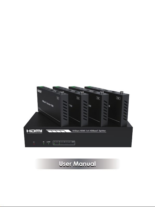
BG-UDA-E14
18Gbps HDMI
1×4 HDBaseT
Splitter
VER 1.0
Page 2

Thank you for purchasing this product
For optimum performance and safety, please read these instructions carefully
before connecting, operating or adjusting this product. Please keep this manual
for future reference.
Surge protection device recommended
This product contains sensitive electrical components that may be damaged
by electrical spikes, surges, electric shock, lighting strikes, etc. Use of surge
protection systems is highly recommended in order to protect and extend the
life of your equipment.
Table of Contents
1. Introduction...........................................................................................
2. Features.................................................................................................
3. Package Contents................................................................................
4. Specifications.......................................................................................
5. Operation Controls and Functions......................................................
5.1 Transmitter.......................................................................................
5.2 HDBaseT Receiver...........................................................................
5.3 IR Pin Definition................................................................................
6. EDID Mode.............................................................................................
7. ASCII Commands.................................................................................
8. Application Example............................................................................
1
1
1
2
3
3
5
6
7
8
12
Page 3

1. Introduction
e BG-UDA-E14 18Gbps HDMI 1x4 HDBaseT Splitter can distribute 1
Th
source signal to any 4 display devices. The HDMI signal transmission distance
can be extended up to 120 meters at the resolution of 4K2K@60Hz, 150
meters at 1080P@60Hz via a single CAT6/6a/7 cable. The product supports
up to 7.1CH HD audio pass-through. Audio extract function and advanced
EDID management are supported.
2. Features
☆ HDMI 2.0b, HDCP 2.2 and HDCP 1.x compliant
☆ Support 18Gbps video bandwidth
☆ Support video resolution up to 4K2K@60Hz 4:4:4
☆ Support HDR, HDR10+, HLG and Dolby vision
☆ Support up to 7.1CH HD audio pass-through
☆ Support digital and analog audio de-embedded output
☆ Extend the signal transmission distance up to 120 meters at the resolution
of 4K2K@60Hz, 150 meters at 1080P@60Hz via a single CAT6/6a/7 cable
☆ Support 1 HDMI input, 1 HDMI loop output and 4 HDBaseT outputs.
☆ IR, RS-232 routed to HDBaseT output
☆ Advanced EDID management
☆ Support one-way POC function (only from transmitter to receiver)
☆ Compact design for easy and flexible installation
3. Package Contents
① 1 × 18Gbps HDMI 1×4 HDBaseT Splitter
② 4 × HDBaseT Receiver
③ 5 × IR Blaster Cable (1.5 meters)
④ 5 × 20K~60KHz IR Receiver Cable (1.5 meters)
⑤ 5 × 3-pin Phoenix Connector
⑥ 1 × 5-pin Phoenix Connector
⑦ 10 × Mounting Ear
⑧ 1 × 24V/2.7A DC Locking Power Adapter
⑨ 1 × User Manual
-1-
Page 4

4. Specifications
Technical
HDMI Compliance HDMI 2.0b
HDCP Compliance
Video Bandwidth 594MHz/18Gbps
Video Resolution
Color Depth
Color Space RGB 4:4:4, YCbCr 4:4:4 / 4:2:2 / 4:2:0
HDR
HDMI Audio Formats
Coaxial Audio Formats PCM2.0, Dolby Digital / Plus, DTS 2.0/5.1
Analog Audio Formats
ESD Protection
Connection
Input
Output
Control
HDCP 2.2/1.x
Up to 4k2k@60Hz 4:4:4
8-bit,10-bit,12-bit(1080p@60Hz)
8-bit (4K2K@60Hz YUV4:4:4)
8-bit,10-bit,12-bit(4K2K@60Hz YCbCr 4:2:2/4:2:0)
Support HDR, HDR10+, HLG, Dolby vision
LPCM 2.0/2.1/5.1/6.1/7.1, Dolby Digital, Dolby TrueHD,
Dolby Digital Plus(DD+), DTS-ES, DTS HD Master,
DTS HD-HRA, DTS-X
PCM 2.0CH
Human body model—±8kV (Air-gap discharge) &
±4kV (Contact discharge)
1×HDMI Type A (19-pin female)
1×HDMI Type A (19-pin female)
4x HDBaseT OUT [RJ45]
1x Coaxial Audio OUT [RCA]
1x L/R Audio OUT [5-pin phoenix connector]
1×RS-232 (3-pin phoenix connector)
1x EDID DIP switch [5-pin]
1x IR IN [3.5mm Stereo Mini-jack]
1x IR OUT [3.5mm Stereo Mini-jack]
-2-
Page 5
Mechanical
Housing Metal Enclosure
Silkscreen Color Black
Dimensions
Weight
Power Supply
Power Consumption 35W
Operation
Temperature
Storage Temperature -20°C ~ 60°C / -4°F ~ 140°F
Relative Humidity 20~90% RH (non-condensing)
Transmitter: 220mm (W) × 130mm (D) × 40mm (H)
Receiver: 140mm (W) × 65mm (D) × 18mm (H)
Transmitter: 853g
Receiver: 246g
Input: AC100 - 240V 50/60Hz, Output: DC 24V/2.7A
(US/EU standards, CE/FCC/UL certified)
0°C ~ 40°C / 32°F ~ 104°F
5. Operation Controls and Functions
5.1 Transmitter
Front Panel
18Gbps HDMI 1x4 HDBaseT Splitter
1 2 3 4IN LOOP OUT
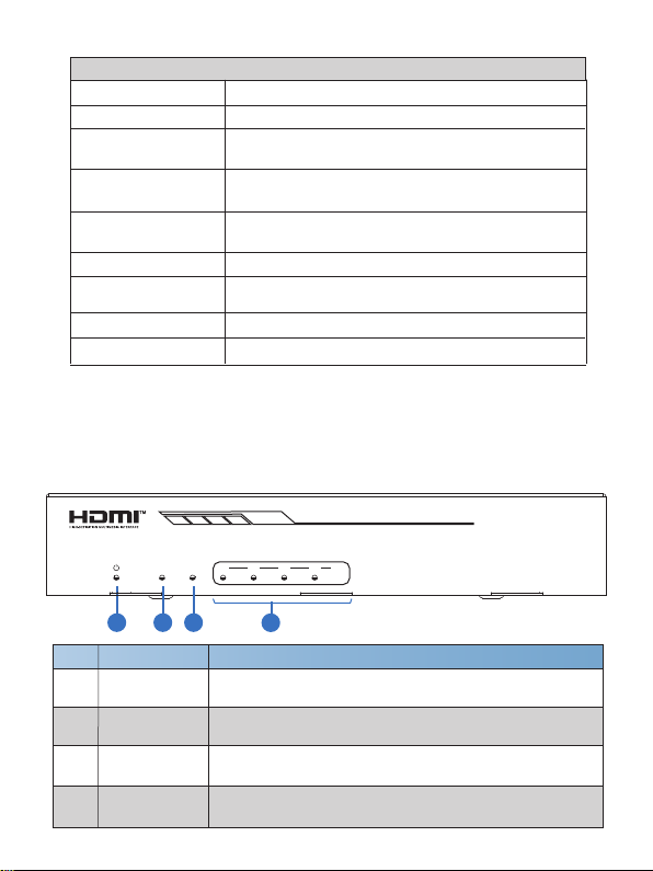
1
2 3
No. Name Function Description
1
POWER LED
IN LED
2
LOOP LED
3
4
OUT(1~4) LED
4
When the device is powered on, the red power LED will
be on.
When the HDMI IN port connects an active source device,
the green LED will be on.
When the HDMI LOOP OUT port connects an active
display device, the green LED will be on.
When the
Receiver, the corresponding green OUT LED will be on.
HDBT OUTPUT port connects an HDBaseT
1/5
3
4
-3-
Page 6
Rear Panel
TX RX
1
0
RS-232
2
IN OUT
IR
IN
3
HDMI
LOOP OUT
4
AUDIO OUT
1
HDBT OUTPUT
2 3 4
1
EDID
5
ON
OFF
DC 24V
6
7
8
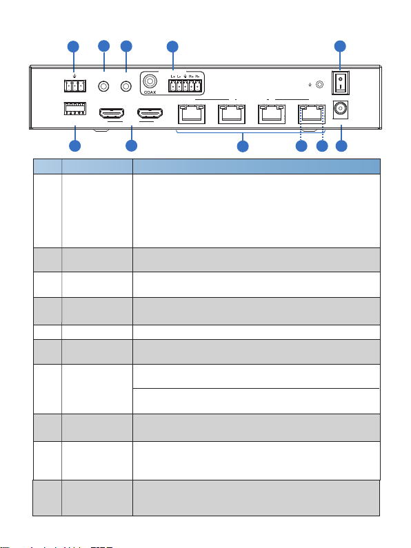
No. Name Function Description
Connect to a PC or control system via a 3-pin phoenix
connector cable for three functions:
1
RS-232
1, Firmware update;
2, Control the Splitter via RS-232 commands;
3, RS-232 signal pass-through (from transmitter to
receiver or from receiver to transmitter).
IR IN
2
3
IR OUT
AUDIO OUT
4
(COAX, L/R)
POWER switch Press this switch to power on/off the device.
5
EDID DIP
6
switch
HDMI port
7
Connect to IR receiver cable, the IR receive signal will
emit to “IR OUT” port of the HDBaseT Receiver.
Connect to IR blaster cable, the IR emit signal is from “IR
IN” port of the HDBaseT Receiver.
Coaxial/balanced audio output port, connect to amplifer or
speaker.
Used to set EDID mode. Please refer to Section “6. EDID
Mode” for details.
3
4
IN: HDMI input port, connect to HDMI source device such
as DVD or set-top box with an HDMI cable.
LOOP OUT: HDMI loop output port, connect to the HDMI
display device such as TV or Monitor with an HDMI cable.
HDBT OUTPUT
8
port (1~4)
Link Signal
9
Indicator lamp
(Green)
Data Signal
Indicator lamp
10
(Orange)
Connect to the HDBT IN port of the HDBaseT receiver
with a CAT cable.
▪ Illuminate: Transmitter and receiver are connected.
▪ Dark: Transmitter and receiver are not connected.
▪ Illuminate: There is signal transmission between
the transmitter and the receiver.
▪ Dark: No signal transmission.
-4-
9 10
11
Page 7

11
DC 24V
5.2 HDBaseT Receiver
1 2
Plug the DC 24V power supply into the unit and connect
the adaptor to an AC outlet. (Note: The transmitter can
power the receiver via a CAT cable.)
SERVICE
DC 24V
HDBT IN
HDMI OUT
AUDIO OUT
IR IN IR OUT
3 84 95 6 7
No. Name Function Description
1
Power Indicator
2
SERVICE port
When the receiver is powered on, the power indicator will
be on.
Used for firmware update.
Plug DC 24V/1A power supply into the unit and connect
3
DC 24V
the adapter to an AC outlet.
(Note: The HDBaseT receiver also can be powered by the
transmitter via a CAT cable.)
4
HDBT IN
5
HDMI OUT
6
AUDIO OUT
7
IR IN
8
IR OUT
Connect to the HDBT OUTPUT port on the transmitter
with a CAT cable.
HDMI output port, connect to HDMI display device such
as TV or Projector with an HDMI cable.
Audio output port, connect to amplifer or speaker.
Connect to the IR Receiver cable. The IR signal will send
to the IR OUT port of the transmitter.
Connect to the IR blaster cable, the IR signal is from IR
IN port of the transmitter.
3-pin Phoenix connector for RS-232 command
9 RS-232
transmission. The RS-232 command will pass-through
from transmitter to receiver or from receiver to transmitter.
-5-
Page 8
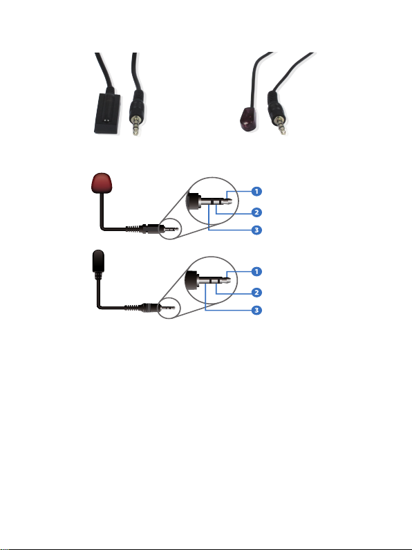
5.3 IR Pin Definition
IR Receiver
IR Blaster
IR Receiver
IR Blaster
IR Blaster Signal
Power
NC
IR Signal
Power
Grounding
-6-
Page 9

6. EDID Mode
The defined EDID setting list of the product is shown as below:
EDID Mode EDID Description
11111 1080P, Stereo Audio 2.0
11110
1110 1
1110 0
110 11
11010
11001
11000
10 111
10110
10101
10100
10011
10010
10001
10000
01111
0111 0
01101 4K2K60Hz_444, Stereo Audio 2.0 HDR
01100
01011
01010
01001
01000
00 111
00110 COPY_FROM_HDBT OUT4
00101
00100
00011
00010
00001
00000
1080P, Dolby/DTS 5.1
1080P, HD Audio 7.1
1080I, Stereo Audio 2.0
1080I, Dolby/DTS 5.1
1080I, HD Audio 7.1
1080P 3D, Stereo Audio 2.0
1080P 3D, Dolby/DTS 5.1
1080P 3D, HD Audio 7.1
4K2K30Hz_444, Stereo Audio 2.0
4K2K30Hz_444, Dolby/DTS 5.1
4K2K30Hz_444, HD Audio 7.1
4K2K60Hz_420, Stereo Audio 2.0
4K2K60Hz_420, Dolby/DTS 5.1
4K2K60Hz_420, HD Audio 7.1
4K2K60Hz_444, Stereo Audio 2.0
4K2K60Hz_444, Dolby/DTS 5.1
4K2K60Hz_444, HD Audio 7.1
4K2K60Hz_444, Dolby/DTS 5.1 HDR
4K2K60Hz_444, HD Audio 7.1HDR
COPY_FROM_LOOP OUT
COPY_FROM_HDBT OUT1
COPY_FROM_HDBT OUT2
COPY_FROM_HDBT OUT3
1080P, Stereo Audio 2.0
1080P, Stereo Audio 2.0
1080P, Stereo Audio 2.0
1080P, Stereo Audio 2.0
1080P, Stereo Audio 2.0
PC control mode
-7-
Page 10

7. ASCII Commands
The product also supports ASCII command control. Connect the RS-232 port
of the product to a PC with a 3-pin phoenix connector cable. Then, open a
Serial Command tool on PC to send ASCII commands to control the product.
The ASCII command list about the product is shown as below.
ASCII Commands
Serial port protocol. Baud rate: 115200, Data bits: 8bit, Stop bits:1, Check bit: 0
x - Parameter 1
y - Parameter 2
! - Delimiter
Command Code
Power
s power z!
r power! Get current power state power on/power off
s reboot! Reboot the device
System Setup
help! List all commands
r type! Get device model HDC-SPB14H150
r status! Get device current status
r fw version! Get Firmware version
r link in!
r link out y!
s reset! Reset to factory defaults
Function Description Feedback
Power on/off the device,z=0~1
(z=0 power off, z=1 power on)
Get the connection status of
the input port
Get the connection status of
the y output port, y=0~5(0=all,
1~4=HDBT 1~4, 5 = loop out)
Example
s power 1!
r power!
s reboot!
help!
r type!
r status!
r fw version!
r link in!
r link out 1!
s reset!
Power on
System Initializing...
Initialization Finished!
FW version x.xx.xx
Reboot…
System Initializing...
Initialization Finished!
FW version x.xx.xx
Get the unit all status:
power,
in/out connection,
edid mode
MCU BOOT: Vx.xx.xx
MCU APP: Vx.xx.xx
HDMI IN: connect
hdmi loop out:
connect
hdbt output 1: connect
Reset to factory
defaults
System Initializing...
Initialization Finished!
FW version x.xx.xx
-8-
Default Setting
power on
Page 11

Command Code
Output Setting
s hdmi stream z!
s hdmi hdcp z!
s hdbt y hdcp z!
s hdbt y stream z!
r hdmi stream!
r hdmi hdcp!
r hdbt y hdcp!
r hdbt stream!
Function Description Feedback
Set hdmi loop output stream
on/off
z=0~1(0:disable,1:enable)
Set hdmi loop output hdcp on/
off
z=0~1(0:disable,1:enable)
Set hdbt output y hdcp on/off,
y=0~4(0=all) z=0~1(0:disable,
1:enable)
Set hdbt output y stream on/
off, y=0~4(0=all) z=0~1
(0:disable,1:enable)
Get hdmi loop out stream
status
Get hdmi loop out hdcp status
Get hdbt output y hdcp status,
y=0~4(0=all)
Get hdbt output y stream
status, y=0~4(0=all)
Example
s hdmi stream 1 !
s hdmi hdcp 1!
s hdbt 1 hdcp 1 !
s hdbt 0 hdcp 1 !
s hdbt 1 stream
1 !
s hdbt 0 stream
1 !
r hdmi stream!
r hdmi hdcp!
r hdbt 1 hdcp!
r hdbt 1 stream!
Enable hdmi loop out
stream
Disable hdmi loop out
stream
Enable hdmi loop out
hdcp
Disable hdmi loop out
hdcp
Enable hdbt output 1
hdcp
Disable hdbt output 1
hdcp
Enable hdbt all
outputs hdcp
Disable hdbt all
outputs hdcp
Enable hdbt output 1
stream
Disable hdbt output 1
stream
Enable hdbt all
outputs stream
Disable hdbt all
outputs stream
Enable hdmi output
stream
Enable hdmi output
hdcp
Enable hdbt output 1
hdcp
Enable hdbt output 1
stream
Default Setting
enable
enable
enable
enable
-9-
Page 12

Command Code
EDID Setting
s edid in from z!
s edid user1 00
FF FF FF FF …!
r edid user1! Get user1 EDID data
r edid in! Get EDID status of the input
r edid in data!
Function Description Feedback
Set input EDID from default
EDID z, z=1~27
1, 1080p,Stereo Audio 2.0
2, 1080p,Dolby/DTS 5.1
3, 1080p,HD Audio 7.1
4, 1080i,Stereo Audio 2.0
5, 1080i,Dolby/DTS 5.1
6, 1080i,HD Audio 7.1
7, 3D,Stereo Audio 2.0
8, 3D,Dolby/DTS 5.1
9, 3D,HD Audio 7.1
10, 4K2K30_444,
Stereo Audio 2.0
11, 4K2K30_444,Dolby/DTS 5.1
12, 4K2K30_444,HD Audio 7.1
13, 4K2K60_420,
Stereo Audio 2.0
14, 4K2K60_420,
Dolby/DTS 5.1
15, 4K2K60_420,HD Audio 7.1
16, 4K2K60_444,
Stereo Audio 2.0
17, 4K2K60_444,
Dolby/DTS 5.1
18, 4K2K60_444,HD Audio 7.1
19, 4K2K60_444,
Stereo Audio 2.0 HDR
20, 4K2K60_444,
Dolby/DTS 5.1 HDR
21, 4K2K60_444,
HD Audio 7.1 HDR
22, copy from hdmi loop out
23, copy from hdbt output 1
24, copy from hdbt output 2
25, copy from hdbt output 3
26, copy from hdbt output 4
27, use user1 EDID
Set user1 EDID data
Get the EDID data of the hdmi
input
Example
s edid in from 1!
s edid user1 00
ff ff ff ff …. !
r edid user1!
r edid in!
r edid in data!
-10-
input EDID:1080p,
Stereo Audio 2.0
Please toggle EDID
dip switch to 00000!
user1 EDID data: 00
FF FF ….
user1 EDID data : 00
FF FF FF FF FF FF
00 ………
input EDID: 4K2K60_
444,Stereo Audio 2.0
EDID data : 00 FF FF
FF FF FF FF 00 ……
Default Setting
1080p,Stereo
Audio 2.0
Page 13

Command Code
RS-232 BYPASS Setting
s rs232 bypass
hdbt y!
r rs232 bypass!
s device baud
w size x stop y
parity z!
s rs232 time x!
Function Description Feedback
Set RS-232 port connect to
HDBT out1 Receiver RS-232
port, y=0~5( 0=all,
1~4= hdbt out 1~4 5=NC)
Get RS-232 port connect to
HDBT out receiver RS-232
port
Set receiver control device
COM port setting, w=2400,
4800,9600,19200,38400,
57600,115200, x=7,8
y=1,2, z=none, even,odd
set send RS232 command
wait time
x=200~5000ms
Example
s rs232 bypass
hdbt 1!
r rs232 bypass!
s device baud
57600 size 8
stop 1 parity
none!
s rs232 time
200!
RS-232 connect to
HDBT OUT1
RS-232 not connect
to HDBT OUT
RS-232 connect to
HDBT OUT1
RS-232 connect to all
HDBT OUT
RS-232 not connect
to HDBT OUT
receiver device COM
port setting
baudrate: 57600
data size :8, stop:1
parity: none
send RS-232
command wait time
200ms
Default Setting
y=0
200ms
-11-
Page 14
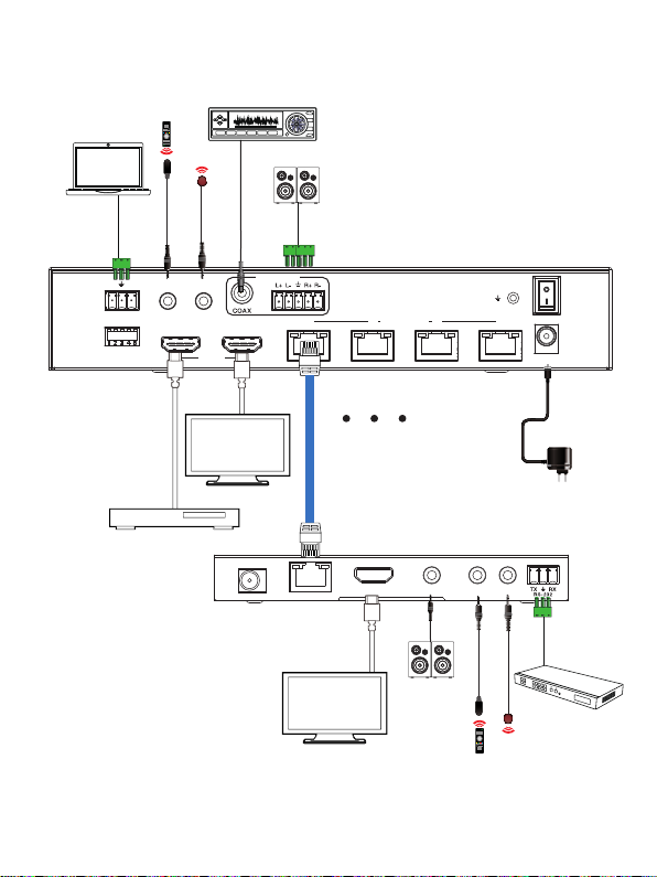
8. Application Example
IR Blaster
IR
IN
HDMI
Amplifier
AUDIO OUT
LOOP OUT
PC
TX RX
RS-232
1
0
IR Receiver
IN OUT
EDID
2.0 Speakers
1
LAN
Transmitter
HDBT OUTPUT
2 3 4
ON
OFF
DC 24V
UHDTV
DVD or Blu-ray Player
DC 24V
Cat 6/6a/7
LAN
HDBT IN
UHDTV
-12-
Receiver
HDMI OUT
2.0 Speakers
IR Receiver
AUDIO OUT
IR IN IR OUT
IR Blaster
Power Supply
HDMI Matrix with
RS-232 function
 Loading...