

BYTES P4KE10, P4KE11, P4KE10C, P4KE100C, P4KE10CA Datasheet
...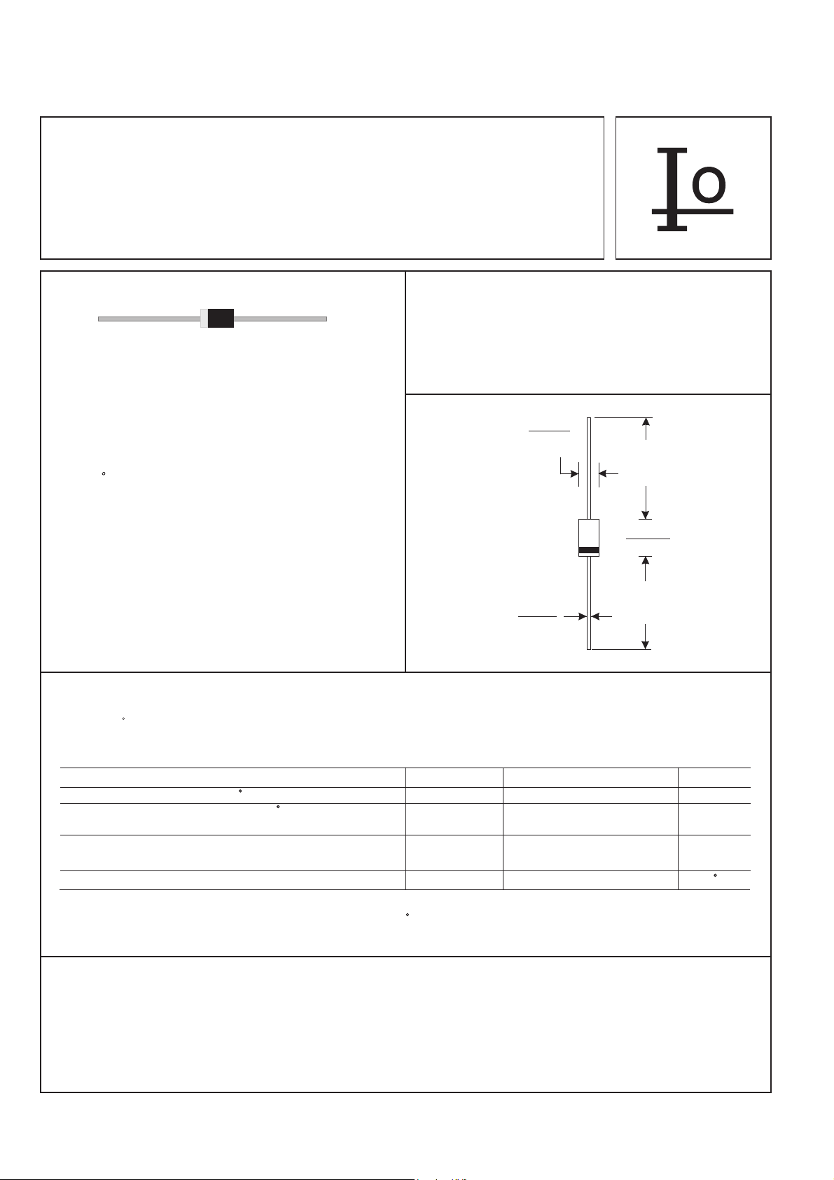
P4KE SERIES
400 WATT PEAK POWER TRANSIENT VOLTAGE SUPPRESSORS
VOLTAGE RANGE
6.8 to 440 Volts
FEATURES
* 400 Watts Surge Capability at 1ms
* Excellent clamping capability
* Low zener impedance
* Fast response time: Typically less than
1.0ps from 0 volt to BV min.
* Typical I less than 1 A above 10VR µ
* High temperature soldering guaranteed:
260 C / 10 seconds / .375"(9.5mm) lead
length, 5lbs.(2.3kg) tension
400 Watts Peak Power
1.0 Watts Steady State
DO-41
.107(2.7)
.080(2.0)
DIA.
MECHANICAL DATA
* Case: Molded plastic
* Epoxy: UL 94V-0 rate flame retardant
* Lead: Axial leads, solderable per MIL-STD-202,
method 208 guranteed
* Polarity: Color band denotes cathode end
* Mounting position: Any
*
Weight: 0.34 grams
.034(.9)
.028(.7)
DIA.
Dimensions in inches and (millimeters)
MAXIMUM RATINGS AND ELECTRICAL CHARACTERISTICS
Rating 25 C ambient temperature uniess otherwies specified.
Single phase half wave, 60Hz, resistive or inductive load.
For capacitive load, derate current by 20%.
1.0(25.4)
MIN.
.205(5.2)
.166(4.2)
1.0(25.4)
MIN.
RATINGS SYMBOL VALUE UNITS
RATINGS SYMBOL VALUE UNITS
Peak Power Dissipation at T =25 C, T =1ms(NOTE 1) P Minimum 400 WattsA P PK
Peak Power Dissipation at T =25 C, T =1ms(NOTE 1) P Minimum 400 WattsA P PK
Steady State Power Dissipation at T =75 CL
Steady State Power Dissipation at T =75 CL
Lead Length .375"(9.5mm) (NOTE 2)
Lead Length .375"(9.5mm) (NOTE 2)
Peak Forward Surge Current at 8.3ms Single Half Sine-Wave
Peak Forward Surge Current at 8.3ms Single Half Sine-Wave
superimposed on rated load (JEDEC method) (NOTE 3)
superimposed on rated load (JEDEC method) (NOTE 3)
Operating and Storage Temperature Range T , T -55 to +175 CJ STG
Operating and Storage Temperature Range T , T -55 to +175 CJ STG
NOTES:
1. Non-repetitive current pulse per Fig. 3 and derated above T =25 C per Fig. 2.
2. Mounted on Copper Pad area of 1.6" X 1.6" (40mm X 40mm) per Fig.5.
3. 8.3ms single half sine-wave, duty cycle = 4 pulses per minute maximum.
A
P 1.0 WattsD
P 1.0 WattsD
I 40 AmpsFSM
I 40 AmpsFSM
DEVICES FOR BIPOLAR APPLICATIONS
1. For Bidirectional use C or CA Suffix for types P4KE6.8 thru P4KE440.
2. Electrical characteristics apply in both directions.
132
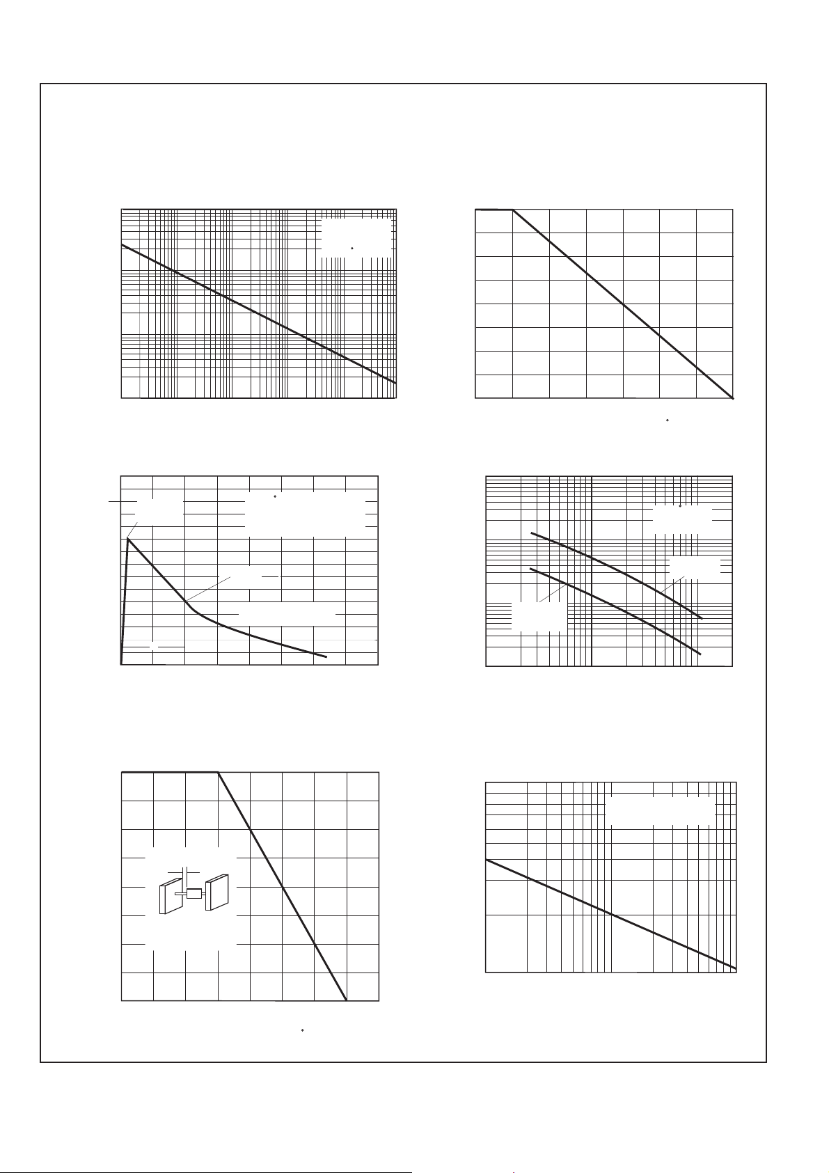
RATING AND CHARACTERISTIC CURVES (P4KE SERIES)
FIG.1-PEAK PULSE POWER DERATING CURVE
100
10
1.0
P , PEAK PULSE POWER, KWPPM
0.1
0.1 s 1.0 s 10 s 100 s 1.0ms 10ms µ µ µ µ
td, PULSE WIDTH, sec.
FIG.3-PULSE WAVE FORM
150
T =25 C
tf=10 s
µ
Peak Value
I
PPM
100
50
I , PEAK PULSE CURRENT, %PPM
td
0
0 1.0 2.0 3.0 4.0
A
Pulse Width (td) is defined
as the point where the Peak
Current Deacys to 50% of Ipp
Half Value-IPPM
2
10/1000 sec Waveform
µ
as Defined by R.E.A.
e-kt
t, TIME, ms
Non-Repetitive
Pulse Waveform
Shown in Fig. 3
T =25 CA
FIG.2-PULSE DERATING CURVE
100
75
PP PP
50
25
PEAK PULSE POWER(P ) OR CURRENT(I )
DERATING IN PERCENTAGE
0
0 25 50 75 100 125 150 175
T , AMBIENT TEMPERATURE ( C)A
FIG.4-TYPICAL JUNCTION CAPACITANCE
100,000
T =25 C
J
f=1.0MHz
10,000
1,000
C , CAPACITANCE, pFJ
100
Measured at
Stand-Off
Voltage(V )MW
1.0 2.0 5.0 10 20 50 100 200
V(BR), BREAKDOWN VOLTAGE, VOLTS
Vsig=50mVp-p
Measued at
Zero Bias
FIG.5-STEADY STATE POWER DERATING CURVE
1.00
0.75
L=.375"(9.5mm)
0.50
40mm x 40mm x 1mm
Copper Heat Sink
0.25
Pm( ), STEADY STATE POWER DISSIPATION, WATTSAV
(1.6" x 1.6" x .040")
0
0 25 50 75 100 125 150 175 200
T , LEAD TEMPERATURE ( C)L
133
FIG.6-MAXIMUM NON-REPETITIVE PEAK FORWARD
SURGE CURRENT, UNIDIRECTIONAL
100
T =T max
80
60
40
20
FSM
I , PEAK FORWARD SURGE
CURRENT, AMPERES
10
1 5 10 20 50 100
NUMBER OF CYCLES AT 60Hz
J J
8.3ms Single Half Sine-wave
JEDEC Method
 Loading...