

Page 1
Manual
NÜO FLUX
41762 | 42039
Page 2

2
Page 3
NÜO Flux Manual
Information
GENERAL FEATURES
NÜO FLUX (ref. no.: 42039 and 41762)
- Maximum security proximity reader for 13.56 MHz
contactless MIFARE® Plus, MIFARE® DESFire EV1,
MIFARE® Classic and MIFARE Ultralight® cards.
- Reader status indicated via acoustic-light display.
- Communication encrypted with AES AND 3DES
encryption algorithms.
- IP65 protection.
- Operating temperature from -20 °C to 50 °C for in-
door and outdoor installations.
- References according to black and white model:
- White: 42039
- Black: 41762
Features
NÜO FLUX
41762
42039
REGULATIONS
ISO/IEC 14443 A and B.
AES128 NIST FIPS PUB 197 MIFARE Plus EAL4+ Common Criteria certication.
NFC MIFARE emulation compliant.
EN 60950-1 2001 and A1: 2004.
EN 300 330-2 v1.3.1.
3
Page 4
NÜO Flux Manual
Information Features
TECHNICAL SPECIFICATIONS
NÜO FLUX:
INPUT VOLTAGE 24VDC (11 - 28 VDC)
POWER 1.8 W
CPU 32-bit ARM Microprocessor
READING DISTANCE 5 - 8 cm
MAXIMUM POWER 250 mA
COMMUNICATIONS
CONNECTION 60 cm of 5 mm diameter cable with 6 wires is provided
INPUTS 1 Door sensor input (Detection resistance: <20 Ω)
OUTPUTS 1 lock control output with 24 VDC power supply (250 mA maximum)
ALARM 2 sound levels incorporated for granted access and denied access
2 twisted pairs.
Baud rate: 38400
Protocol: High security communications
Automatically regulated according to environmental conditions.
Colours according to status:
- Red/White: Terminal oine.
- Degraded Red/Pink: Terminal in card enrolment mode.
ILLUMINATION
MATERIALS
INSTALLATION Flush installation for indoor or outdoor use
PROTECTION LEVEL IP65
OPERATING
TEMPERATURE
- Flashing blue: Terminal in rmware update mode.
- Blue: Terminal on standby.
- Green: Access granted.
- Red: Access denied.
- White: Card writing operation.
Manufactured with the highest quality polycarbonate with scratch-resistant
unbreakable glass polycarbonate facing
-20 °C to 50 °C
4
Page 5
NÜO Flux Manual
Information Features
TECHNICAL SPECIFICATIONS
READER DIMENSIONS 92 x 92 x 30 mm (height x width x depth)
READER DIMENSIONS
WITH EMBEDDED
CASE
EMBEDDED CASE
DIMENSIONS
ACCESSORIES
92 x 92 x 57 mm (height x width x depth)
82 x 82 x 52 mm (height x width x depth)
- Embedded case
- Suction cup to remove front glass panel
- Bag with accessories:
- Screws to fasten reader to the embedded case.
- Screws, washers and nuts for surface mounting.
- 3 metres of piped cable with 4 wires (2 twisted pairs) and a female con-
nector
5
Page 6
NÜO Flux Manual
Installation
NÜO FLUX
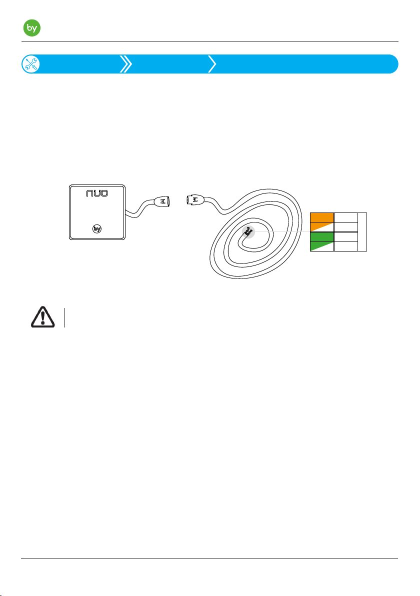
TYPE OF WIRING AND WIRING DISTANCE:
The NÜO FLUX readers incorporates a 4-pin male overhead connector and the corresponding female
connector which joins 3 metres of piped cable with 4 wires (2 twisted pairs). This means that the installation
and wiring to then connect the reader to a single door controller or to the corresponding Wili are both very
simple.
O/W
G/W
+
-
A
BY B US
B
Orange
Green
NÜO FLUX
3 metres of cable
The wiring distance from the reader and the single door controller or Wili should not exceed
15 metres in length.
WIRING SPECIFICATIONS:
The built-in piped cable used to connect the reader has the following technical characteristics:
- Gauge: 0.22 mm
- Arrangement: 2 twisted pairs
- Resistance: <2 Ohms
DISTANCE BETWEEN READERS:
A minimum distance of 12 cm must be maintained if installations are made with doors with 2 input/output readers or with 2 readers that are very close together.
6
Page 7
NÜO Flux Manual
Installation
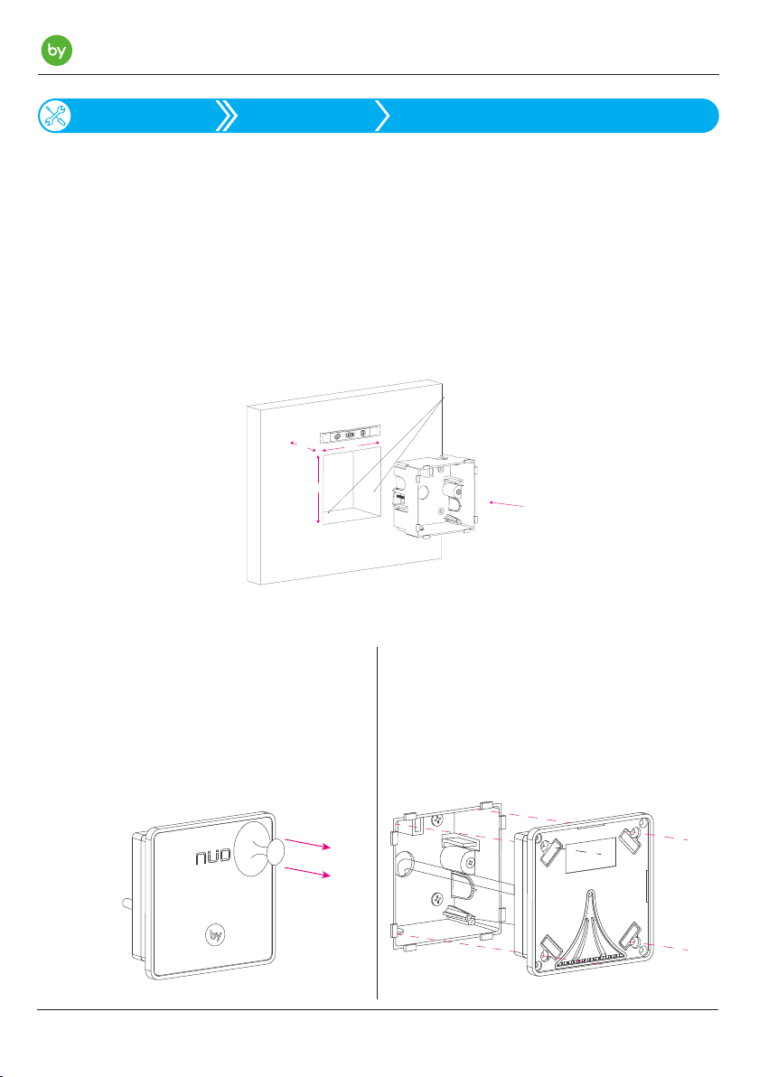
NÜO FLUX Installation on built walls
The NÜO FLUX reader can be ush mounted in various environments. The various installation methods
are described below, covering built walls, plasterboard walls, and integration into other equipment such as
turnstiles or gates:
1. Installation on working surfaces:
1) Using a level, make a hole in the wall for the rear case measuring 82 x 82 mm and 52 mm deep.
Do not forget to pass the reader cable through.
Grout the hole with plaster and place the rear case in the hole.
Plaster
52
82
82
Place the magnet at the top. This magnet will work as a tamper.
Recommended height for installation is between 1.2 and 1.5 m.
2) Remove the NÜO FLUX reader front glass
panel using the suction cup supplied. Place
the suction cup in a corner for ease of operation.
3) Pass the cable through the opening made
and attach the reader to the rear case using
the screws supplied as shown in the drawing.
Finally, replace the front glass panel.
7
Page 8
NÜO Flux Manual
Installation
NÜO FLUX
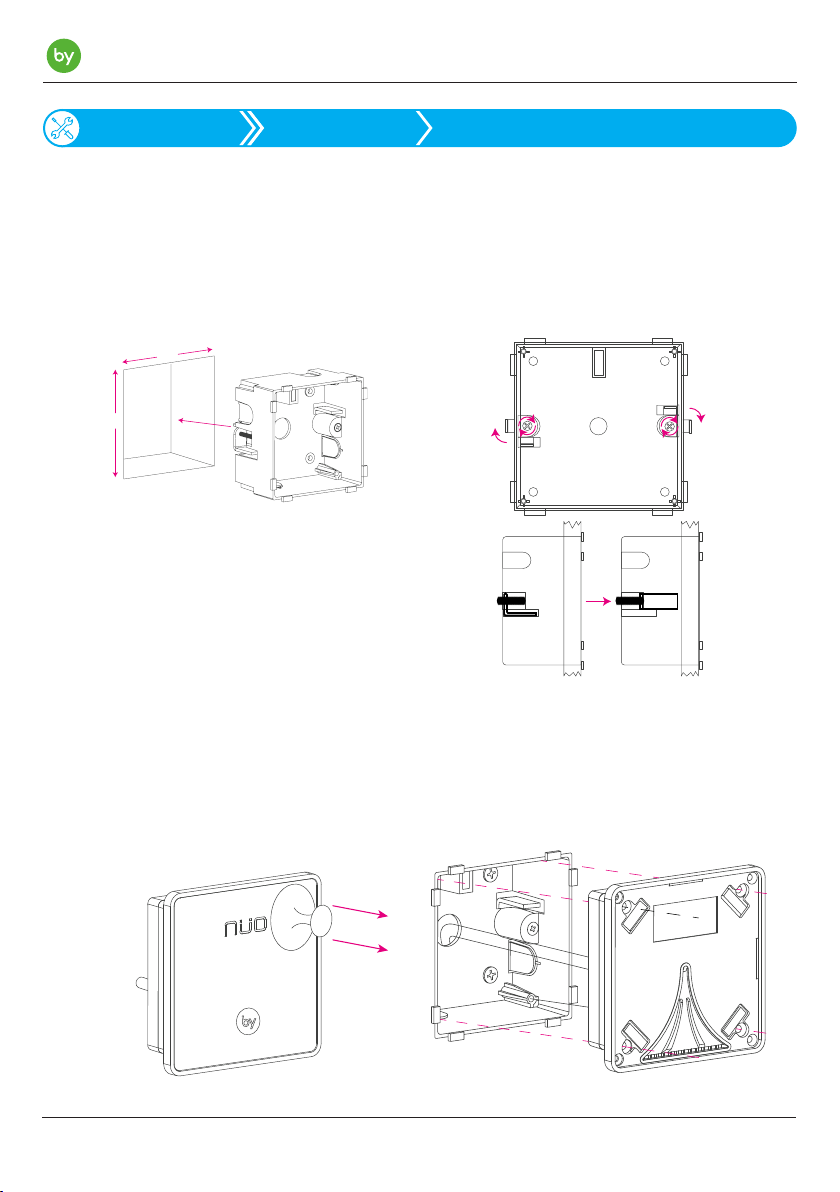
Installation on plasterboard walls
2. Installation on plasterboard walls 10 to 22 mm thick:
1) Using a level, make a hole in the wall for
the rear case measuring 82 x 82 mm. Do not
forget to pass the power and communication
cables through.
82
82
2) Place the case in the hole and screw the
pressure tabs to x the case to the wall. These
tabs apply pressure against the wall as the
screws are turned.
Place the magnet at the top. This magnet
will work as a tamper.
Recommended height for installation is
between 1.2 and 1.5 m.
Plasterboard
Plasterboard
3) Remove the NÜO FLUX reader front glass
panel using the suction cup supplied. Place
the suction cup in a corner for ease of operation.
4) Pass the cable through the opening made
and attach the reader to the rear case using
the screws supplied as shown in the drawing.
Finally, replace the front glass panel.:
8
Page 9
NÜO Flux Manual
Installation
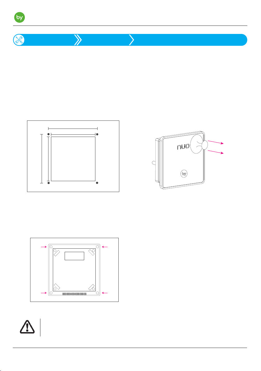
3. Installation in other environments:
1) Using a level, create a niche on the surface
where the reader is to be placed measuring 78
x 78 x 30 mm. Create 4 holes forming a square
measuring 80 x 80 mm for M3 screws. You
can use tapped holes in order to avoid having
to use nuts.
80
78
7880
3) Place the reader in the hole and insert the
screws in the holes located in the corners of
the reader.
NÜO FLUX
Installation in other environments
2) Remove the NÜO FLUX reader front glass
panel using the suction cup supplied. Place
the suction cup in a corner for ease of operation.
4) The equipment can be installed with the
screws, nuts and washers supplied, or if
tapped holes have been used then only the
screws are required. Once secure, place the
front glass panel to complete the installation.
Assembly the equipment on outdoor or indoor surfaces that are free from vibrations.
The wiring shall be suitably protected.
9
Page 10
NÜO Flux Manual
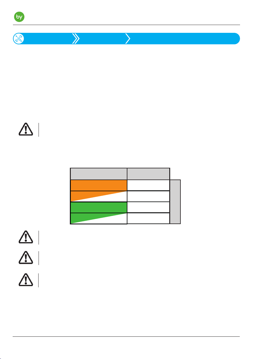
Orange
Orange/White
Green
RS-485-A
RS-485-B
+ 24VDC
BYBUS
Green/White
0V / GND
COLOUR
SIGNAL
Installation
NÜO FLUX readers can be directly connected to two types of devices depending on facility architecture:
- Connection to a Wili.
- Connection to a single door controller.
The connection to be made for both types of devices is exactly the same. The colour code must be followed. For more detailed information, consult the equipment manuals referenced earlier.
Respect the specied input voltage.
READER WIRING:
Wiring
Install the reader using voltage-free power cables.
NÜO readers support an input voltage ranging from 11 to 28 VDC.
24 VDC is recommended in order to avoid possible voltage drops.
These signals must be perfectly isolated in order to prevent damaging the equipment or installation.
10
Page 11

Changes or modifications not expressly approved by the party responsible for compliance could
void the user's authority to operate the equipmentÿ
Note: This equipment has been tested and found to comply with the limits for a Class B digital
device, pursuant to part 15 of the FCC Rules. These limits are designed to provide reasonable
protection against harmful interference in a residential installation. This equipment generates, uses
and can radiate radio frequency energy and, if not installed and used in accordance with the
instructions, may cause harmful interference to radio communications. However, there is no
guarantee that interference will not occur in a particular installation. If this equipment does cause
harmful interference to radio or television reception, which can be determined by turning the
equipment off and on, the user is encouraged to try to correct the interference by one or more of
the following measures:
—Reorient or relocate the receiving antenna.
—Increase the separation between the equipment and receiver.
—Connect the equipment into an outlet on a circuit different from that to which the receiver is
connected.
—Consult the dealer or an experienced radio/TV technician for help.
August 2018Version: 03MT:17485
 Loading...