

Byron Home Easy HE-410, Home Easy HE-420 Installation Instructions Manual
RE-INVENTING THE HOME
HOME
easy
HE-410 & HE-420 IP56
Remote outdoor socket
and Switch
V1.0
The HomeEasy Outdoor Socket kit
allows you to control your outdoor
lighting and ponds etc simply and
easily.
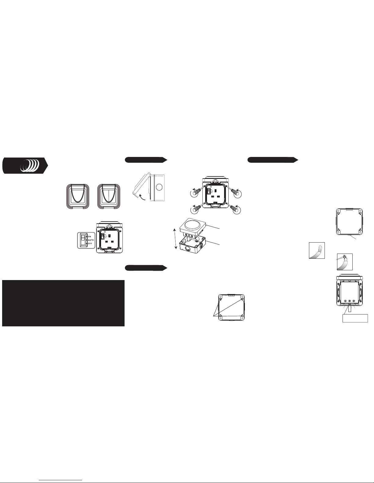
The remote control outdoor socket can
be set to operate in one of three
settings:
AUTO: Allows the remote control outdoor socket to
switch on/off using the remote control, allowing
you to control your outdoor lighting from any point.
ON: Sets the remote control outdoor socket as a
standard outdoor socket.
USE THIS OPTION WHEN USING GARDEN
MACHINERY SUCH AS A LAWNMOWER OR
HEDGECUTTERS.
Remote Switch
Remote Socket
INSTALLATION WARNING:
ON INSTALLATION TURN OFF YOUR MAINS
ELECTRI C SUPPLY
This product should be fitted by a competent person in accordance with the
instructions listed below and with the relavent clauses of the IEE wiring
regulations BS 7671.
The remote outdoor socket should be used in conjunction with a fused spur
connection, all connections to the socket need to be made as instructed,
making sure that the cable used is appropriate for the installation
environment, free from stress & terminals are tightened fully.
1. Open up the front, flip top cover.
2. Unscrew the four screws shown. To
separate the front, from the back of the
unit.
3. After all 4 screws have
been removed, the front will
separate from the back.
Front half
Back half
Opening Unit:
2. Using the back half of the unit as a template, pencil mark all four
corners onto your chosen surface. Making sure 'TOP' (marked on
the casing is at the top.
3. Drill all four marked holes and insert suitable wall plugs for a
number ‘8’ screw (recommended size).
4. Screw to the wall.
Fixing Holes
Mounting Socket:
1: In the back half of the unit, in all four corners are purpose made holes for fixing your
remote socket to your intended surface. TheHE-410 needs to be mounted onto a flat,
vertical surface. Free from grease, loose material and any corrosive substances.
We recommend a house or sturdy garden wall.
Remove Bottom
'Entry Blank'
Wiring Remote Socket:
On the back half of the remote socket you will see that there are 4 circular shaped disks
(‘Entry blanks’) on each side (3 are plastic, 1 is rubber). Depending on if you wish to link up
more than one ‘Outdoor remote socket’ you can remove or replace these disks.
It is recommended that the bottom most ‘Entry blank’ should be removed to gain entry
into the ‘Outdoor Remote Socket’ . This will help keep the moisture out.
If installing the outdoor socket with conduit from the sides or top attachment, a 5mm hole
must be drilled through the bottom left drainage hole. This will allow for any condensation
forming in the conduit, to drain out.
Caution: opening the drainage hole will effect the IP rating of the product. Ensure that
jetted water is not directly sprayed onto the unit.
Do Not drill out the drainage hole when installing the
Outdoor socket into a dusty environment. Always install
the unit via the bottom cable entry, making sure that a
5mm hole is drilled into the lowest point in the conduit
1. Switch off and isolate the mains power before altering
the code setting
4. Send the cable through the conduit and into the
‘Outdoor Remote Socket’.
(Live - Brown)
(Earth - Green & Yellow)
(Neutral - Blue)
Exposed wire
(L = Live - Brown)
(E = Earth - Green & Yellow)
(N = Neutral - Blue)
LEN
(FIG.8)
LEN
Please Note: The Cable is
up inside the box, so that
no wires can be seen.
2: Cut back the cable to reveal 3 separate wires
L= Live Brown
E= Earth Green & Yellow
N= Neutral Blue
3. Now strip each wire, exposing 10mm of its
3: Insert the exposed core wires into their related
terminals and clamp down by tightening the
respective screw. If you are not using 3 core wire:
L= Live Brown
E= Earth Green & Yellow
N= Neutral Blue
1 Gang
2 Gang
OFF: An additional safety feature of the HE410 is the ability to
switch off the power to the unit as per a normal socket.
When installing secondary Outdoor receiver sockets always place the
units approximately 30-40cm apart.
C H Byron
34, Sherwood Rd
Aston Fields
Bromsgrove
B60 3DR
Contact Details :
433MHz
R&TTE
APPROVED
CH Byron Electrical United Kingdom. www.chbyron.com
A
B
DK
FIN
F
D
GR
LT
IRL
I
L
NL
P
E
S
UK
BG
CZ
EST
H
IS
LV
M
N
SK
SLO
CH
PL
RO
0560
Tel: 0845 2301231
Fax: 01527 557701
Web: www.chbyron.com
E-mail:
support@chbyron.com
Help: Occasionally interference from adjacent receiver sockets and low voltage
products (Transformers) can affect the operating range.
Always Try to locate addition outdoor sockets a minimum of 30cm apart.
Contact: Helpline: 0845 2301 231
RF Range: The radio signals operating distance is reduced when the signal has to
pass through walls. The radio signals achieve a range of 30 metres line of sight; this
can be reduced depending on the type of material and localised interference.
Help Section :
WARNING:
You MUST install an earth cable between the origin of the installation and the earth
terminal of the outdoor socket. This must be insulated inside a sleeve protector within
the conduit.
If using metal conduit, earth continuity must be maintained between conduits.Seal
Conduit and conduit entry with a non setting conduit sealant. Contact your local
electrical retailer.
Product Operation:
Pairing/Deleting with Remote Control:
Up to Six remote control units can be paired with each outdoor socket. To pair the
switch and socket together, press the "Learn" button. The LED will start to flash, now
press the selected "On" button on the remote control, the LED will stop flashing. The
units are now paired together, you can test this by pressing the selected "ON/OFF"
button.
Deleting Remote Control:
To delete a remote control that has been paired with an outdoor receiver socket,
simply press the "Learn" button. The LED will start to blink; press the off button on the
remote control, the LED will blink twice to confirm that the remote control has been
removed from the receiver sockets memory.
Remote Socket reset:
To delete all the remote control units from the memory of the receiver socket, hold
the "Learn" button for more than 6 seconds, the LED will start to blink continuously.
Press the learn button again, the LED will blink twice to confirm the deletion of all
remote controls form the receiver memory.
Product Specification:
Remote Control: HE-410
Input: 230V ~50Hz
Range: 30 Metres (Open Distance)
Frequency: 433.92MHz
Max Load: 3000W (Resistive)
IP56 (Lid Clip closed)
Warning: Never Exceed the Product Specification
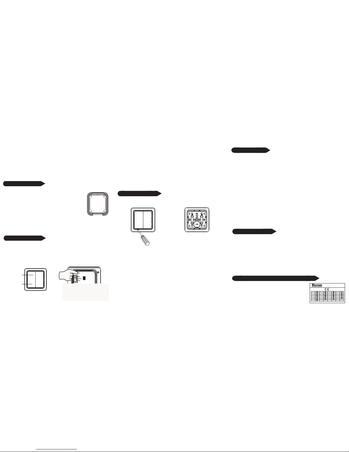
WARNING: attaching the outdoor switch to a metallic surface will reduce the
operating distance.
Remove the switch unit from the protective casing, attach the
casing to the wall using the screws and wall plugs provided.
Reinsert the switch unit into the protective casing making sure
the unit is the correct way up.
Switch Installation:
Remote Control: HE-401/402
Input: CR2032 Battery
Range: 30 Metres (Open Distance)
Frequency: 433.92MHz
Changing Battery:
Remove the switch unit from the protective casing, using a small screwdriver
remove the front cover of the switch unit.
Replace the battery with a new CR2032 battery
(Byron SX100), making sure the polarity is correct.
Replace the front cover and reinsert the switch unit into the protective enclosure.
Always refer to the original instruction when using with additional products.
On
Off
Switch 1 Switch 2
 Loading...