

Page 1
1
L8542497 ENG 10/2009 rev 0
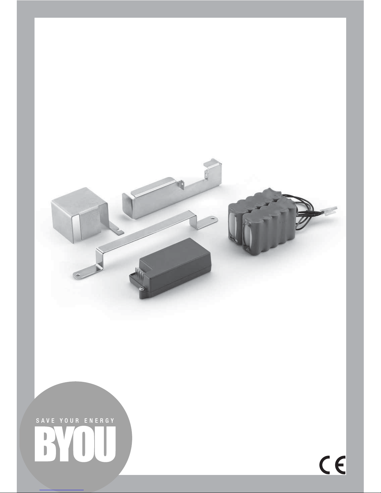
Emergency battery kit
CB.BY
MADE IN ITALY
Page 2
2
INTENDED USE
Emergency battery kit.
The kit can be used with the JUMP, PRETTY, FREEDOM and BEAUTY units made by
BYOU, and allows the device to work temporarily when there is no mains power.
The number of operations that are possible
when there is no power from the mains depends on the batteries’ state of charge, on
the type of device and on climatic factors.
BYOU products are covered by a 2-year
warranty.
However, BYOU srl shall not be responsible for damages caused by improper use or
by the improper installation of products or
components.
The manufacturer may change the descriptions and fi gures in this manual at any time.
Furthermore, the manufacturer reserves the
right to make changes to the products’ technical, construction or commercial features
without necessarily updating this manual at
the same time.
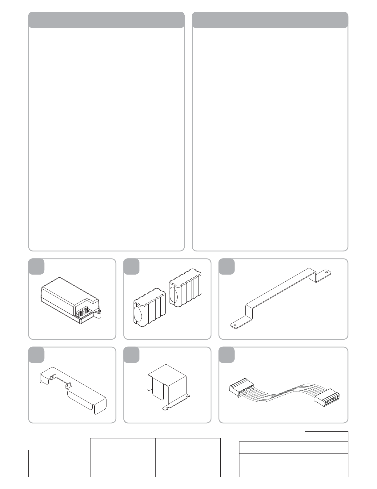
The kit is composed of the following parts:
1) Battery charger board. The battery charger
board must be connected between the batteries and the control station using the cables supplied. The board automatically powers the device when there is no mains power,
and maintains the batteries’ charge when the
device is powered by the mains.
2) Backup batteries. Two 24 V 2100 mAh
battery packs, with quick connector for connection to the battery charger board.
3) Bracket for fastening the batteries to the
motor on the JUMP unit
4) Bracket for fastening the batteries to the
motor on the PRETTY unit
5) Bracket for fastening the batteries inside
the control station’s container on the BEAUTY unit (CP.BTY).
6) Cable for connecting the battery charger
to the control unit.
Product description Contents of kit
1 2
4
3
5 6
TECHNICAL DETAILS CB.BY
Batteries NiMh
Voltage 24Vdc
Charging current 300 mAh
JUMP PRETTY BEAUTY FREEDOM
Average number of cycles when there is no
power from the mains
80 60 60 80
Page 3
3
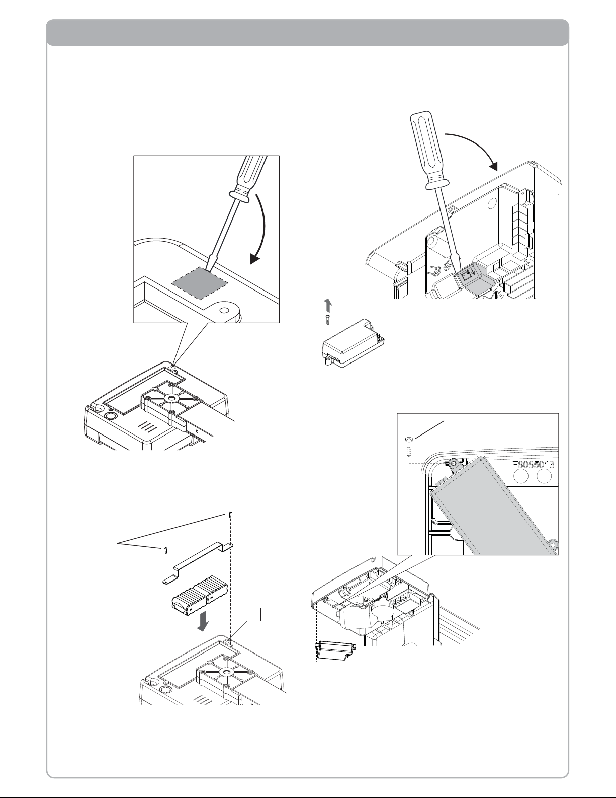
Installation on JUMP unit
Cut off the mains power supply before carrying
out any operation.
Using a screwdriver, open the passage for the
cables (A). If necessary, lower the gearmotor
as described in the instructions for the JUMP
unit:
A
Fasten the batteries to the gearmotor using the
bracket and screws supplied. Pass the connection cable through the cable passage A:
If you previously lowered the gearmotor, return
it to its operating position.
Open the gearmotor assembly following the instructions supplied with the JUMP unit.
Disconnect the battery charger connector
(shown in the fi gure) from the control station’s
cover:
On the battery charger, remove the screw on the side
opposite the terminal board.
Using the screw supplied, install the battery
charger as shown in the fi gure:
Connect the batteries and the battery charger
as described in the “Connections” section.
Close the gearmotor assembly following the
instructions supplied with the JUMP unit.
TCIC 3,5x9,5
TCIC 2,9x22
Page 4
4
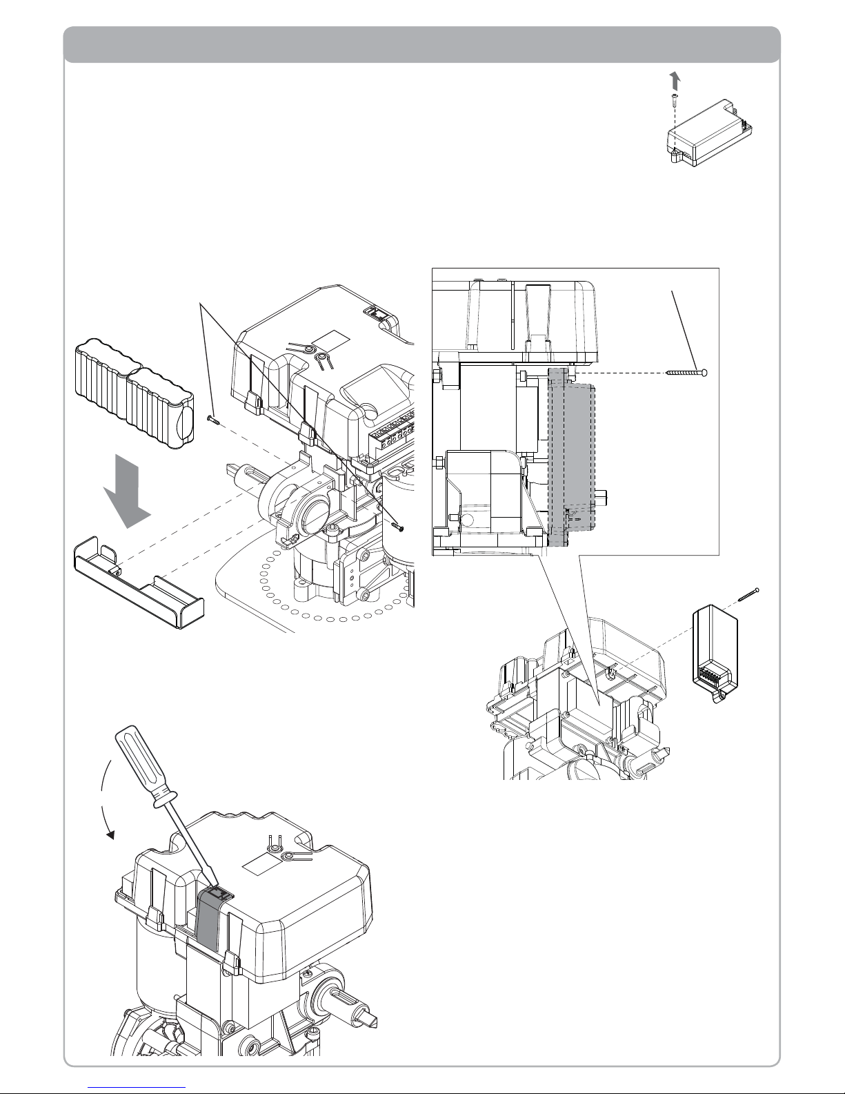
Installation on PRETTY unit
Cut off the mains power supply before carrying
out any operation.
Remove the protective casing from the gearmotor with the control station (PRETTY.A)
following the instructions supplied with the
PRETTY unit.
Install the batteries using the relative bracket
and screws as shown in the fi gure:
On the battery charger, remove the screw on the side
opposite the terminal board.
Disconnect the battery charger connector
(shown in the fi gure) from the control station’s
cover:
Using the screw supplied, install the battery
charger as shown in the fi gure:
Connect the batteries and the battery charger
as described in the “Connections” section.
Close the gearmotor assembly following the
instructions supplied with the PRETTY unit.
TCIC 3,5x9,5
TCIC 3,5x16
Page 5
5
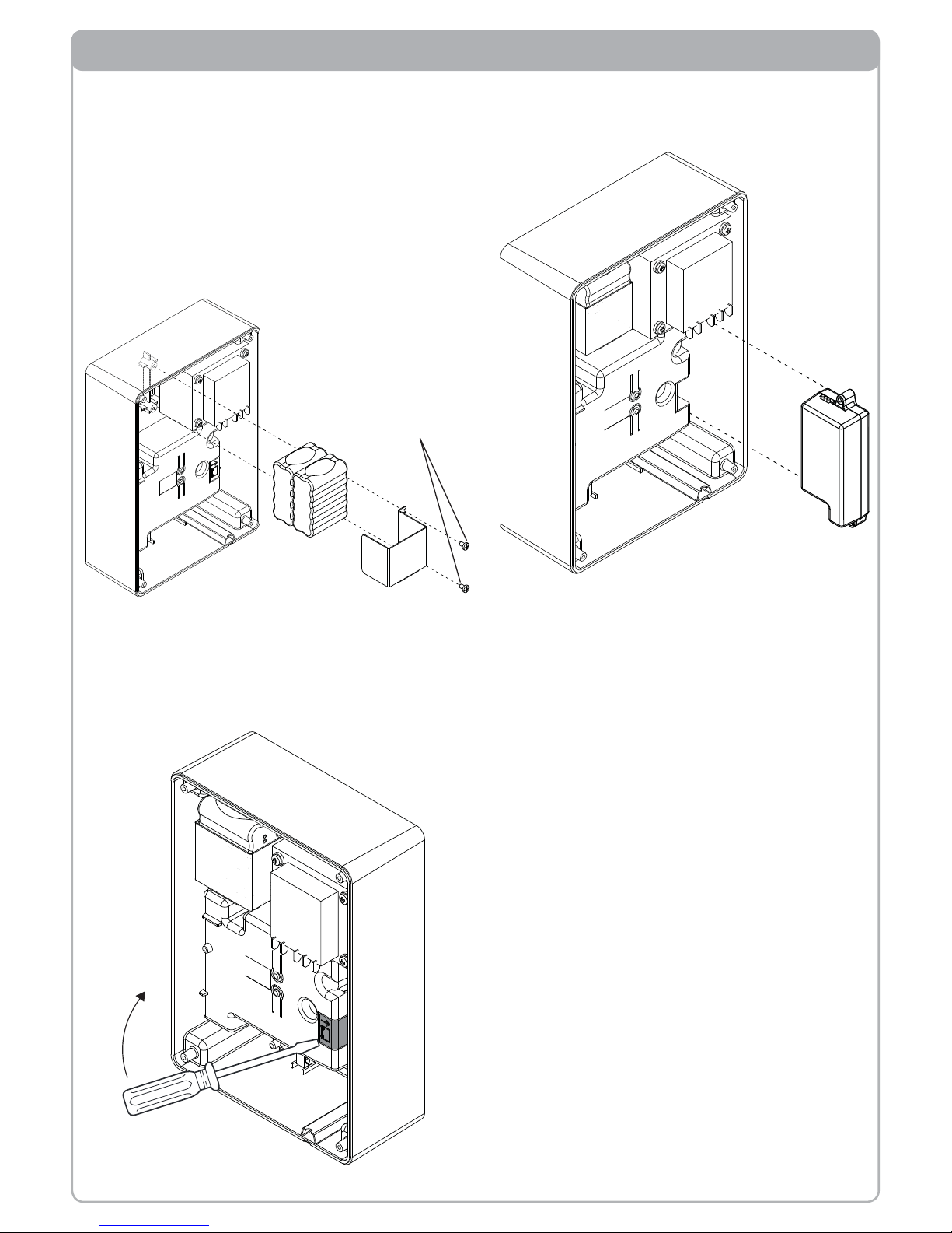
Installation on BEAUTY unit
Connect the batteries and the battery charger
as described in the “Connections” section.
Close the control station following the instructions supplied with the BEAUTY unit.
Cut off the mains power supply before carrying
out any operation.
Open the control station, following the instructions supplied with the BEAUTY unit.
Install the batteries using the relative bracket
and screws as shown in the fi gure:
Disconnect the battery charger connector
(shown in the fi gure) from the control station’s
cover:
Put the battery charger in the position shown
in the fi gure (no screws are required):
TCIC 3,5x9,5
Page 6
6
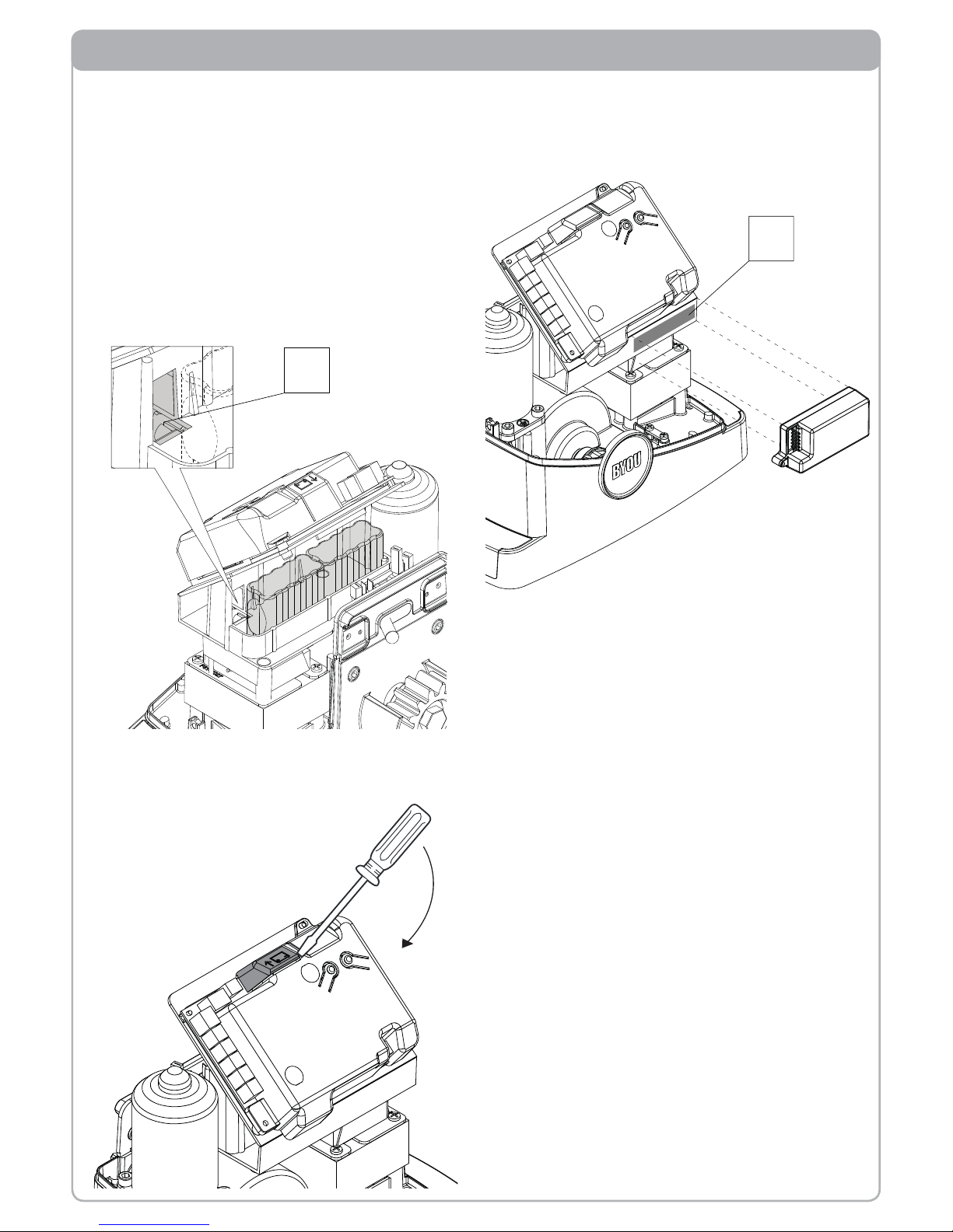
Installation on FREEDOM unit
A
B
Cut off the mains power supply before carrying
out any operation.
Open the electromechanical operator with the
control station following the instructions supplied with the FREEDOM unit.
Install the batteries as shown in the fi gure (no
screws or brackets required) and pass the battery connection cables through slot A:
Disconnect the battery charger connector
(shown in the fi gure) from the control station’s
cover:
Fasten the battery charger as shown in the
fi gure, applying double-sided adhesive tape in
zone B:
Connect the batteries and the battery charger
as described in the “Connections” section.
Close the electromechanical operator with the
control station following the instructions supplied with the FREEDOM unit.
Page 7
7
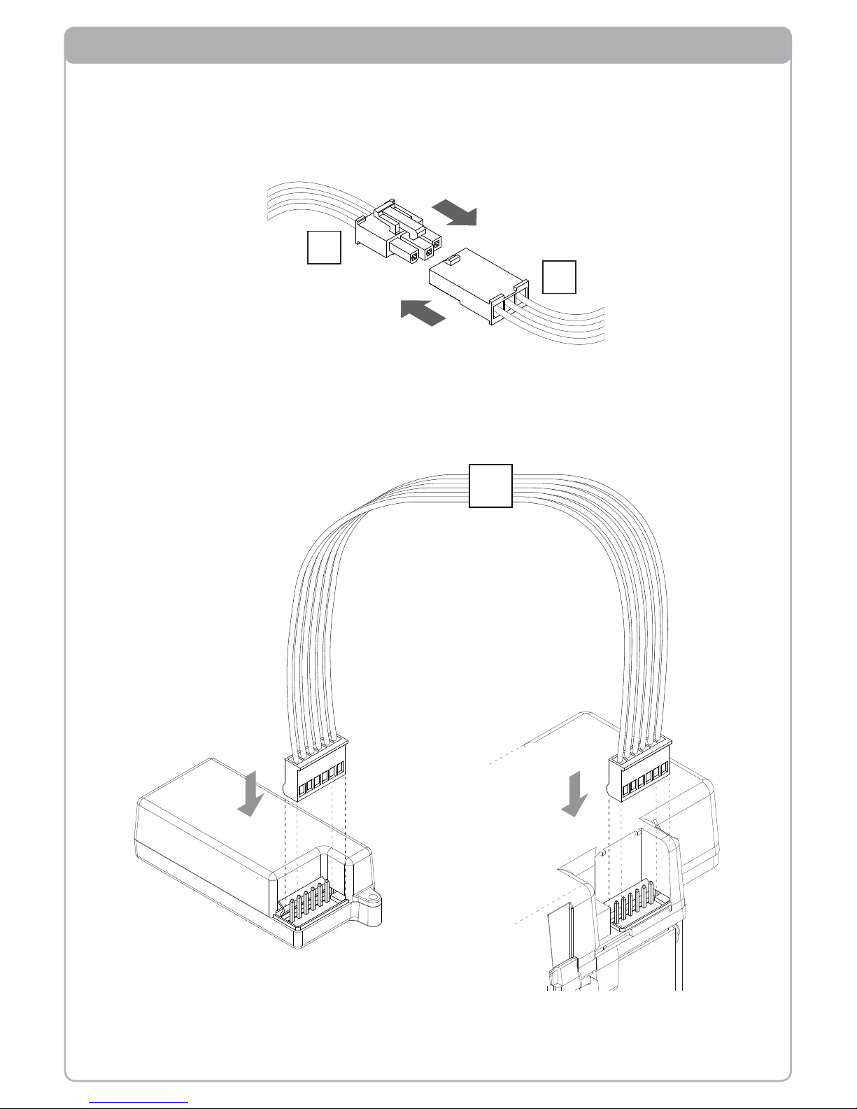
Connections
A
B
Cut off the mains power supply before carrying out any operation.
Connect cable A from the batteries to cable B on the battery charger:
Connect the battery charger to the control unit using cable C (supplied):
C
Page 8

8
BYOU srl _ via dell'Industria 91 _ 36030 Sarcedo (Vicenza) ITALIA _ tel +39 0445 363133 _ fax +39 0445 378 931 _ e-mail: i[email protected] _ web www.byouweb.com
 Loading...