

Page 1
MicroTrak-2001 Manual
Version 0.3 – November 19, 2018
Overview
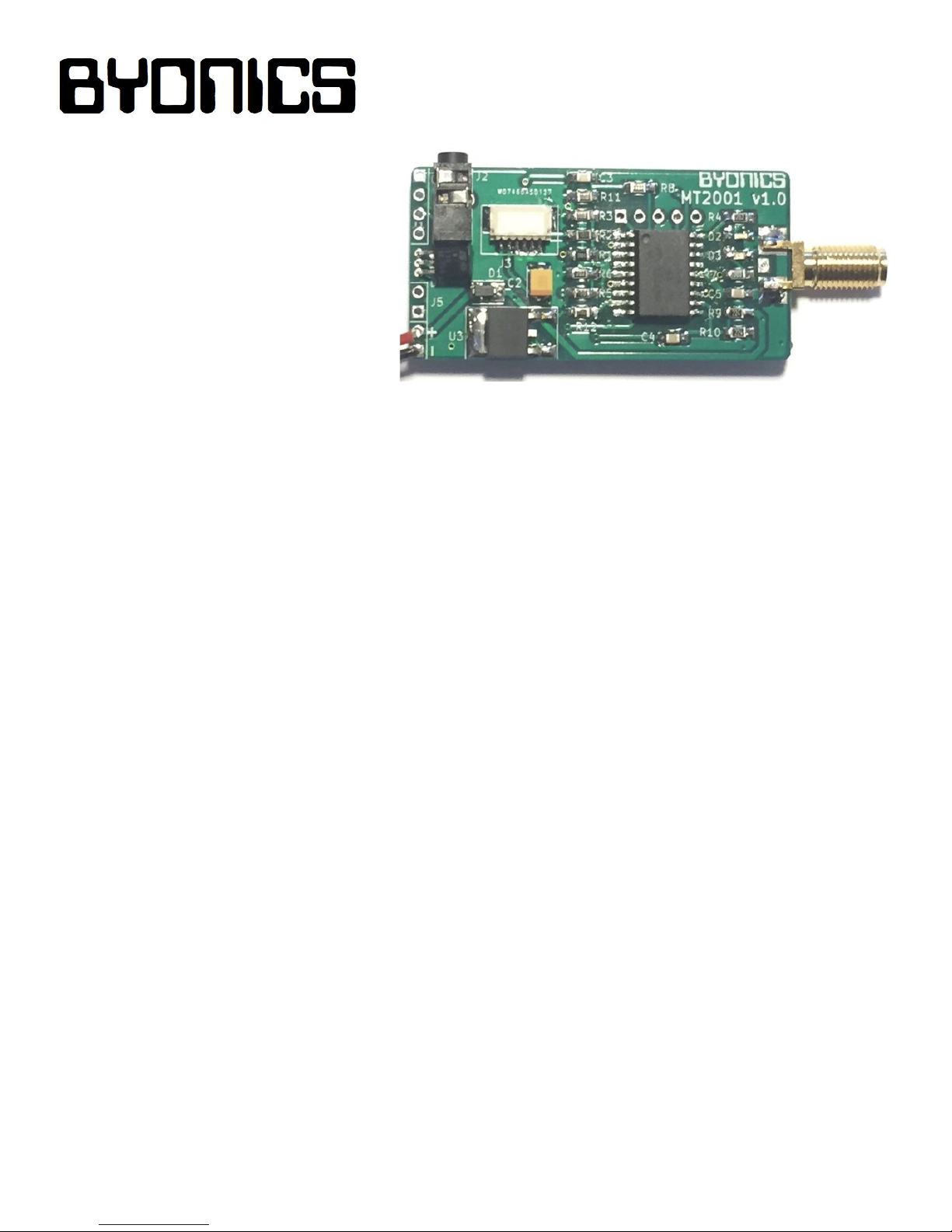
The Micro-Trak 2001 (MT-2001) is a 2meter, frequency agile, 2-watt miniature
APRS (Automatic Position Reporting
System) transmitter designed primarily
for high altitude balloons and other
applications requiring mid-power
transmitters with minimal size and
weight. The MT-2001 replaces the
somewhat larger and heavier MT-2000,
measures only 1” X 2” (excluding SMA) and weighs less than one ounce.
The MT-2001 is based on the Byonics TinyTrak3 controller. It may be ordered pre-configured,
however programming cables are available for the end user to change the configuration at any time.
The Windows TinyTrak3 Configuration program version 1.4.6 may be downloaded for free from the
Byonics website. SMA Antenna and GPS are not included. The MT-2001 is capable of power output
in excess of 2 watts which should allow extremely long air-to-ground ranges, but may not be optimal
for all terrestrial applications.
Power Supply
The MT-2001 requires external power of between 7.2 and 12 volts DC and 800 mA to the J4 pads. It
includes wire power leads in the form of a 9 volt battery wire clip lead, however a typical 9 volt battery
is not adequate for this transmitter. A 2 or 3 cell LiPo battery, or a 6 alkaline AA battery pack (9 volts)
should work well for ground and low altitude operations. For high altitude operations, we recommend
ONLY Energizer “Ultimate Lithium” AA batteries in either the 6 or 8 pack cartridges (9 or 12 volts).
GPS
Connector J3 allows uses of a Byonics GPS receiver module, but any 4800 or 9600 baud,
NMEA-0183 compatible serial GPS may be used. If the MT-2001 will be used with a high altitude
balloon, be sure to get a high altitude capable GPS, such as the Byonics GPS5HA Module, as many
GPS receiver are capped at 60,000 feet. J1 and J2 can also be used to connect a GPS. Both TTL
and RS-232 GPS are supported.
Configurations
Like most TT3-based products, the MT-2001 is capable of storing two independent operation profiles,
which are entered during the computer configuration process. A optional SPST switch can be
connected to J5 to manually select the desired the configuration.
Page 2
RF Output Connector
The MT-2001 uses a female, edge-mounted SMA connector for the RF output, and is very flexible in
the type of antennae it will accept. The need for antenna gain typically increases with proximity to the
ground. For high altitude balloon applications, we recommend the Byonics V6, a center-fed, half-wave
dipole antenna. Use care when inserting mating connectors into the SMA connector, as off-axis
insertion can easily cause bent pins and damage the MT-2001. Avoid regularly connecting and
disconnect an antenna, as SMA connectors have a connection life cycle. Do not place any significant
strain on the SMA connector.
LED Indicator
The MT-2001 has two LED’s to report on the unit’s status: a green LED for GPS status, and a red
LED for transmit. There is no “power on” indicator per se. Both LEDs will flash on powerup. If they
flash continuously, the unit is resetting, typically due to low battery voltage level or poor antenna with
high SWR. Shortly after applying power, the MT-2001 will send an initial ID packet and the red LED
will light during this transmission. When the MT-2001 recognizes a GPS signal, the green LED will
begin to flash. Once the GPS acquires valid position data, the green LED will light solidly, and the
MT-2001 will transmit a position packet.
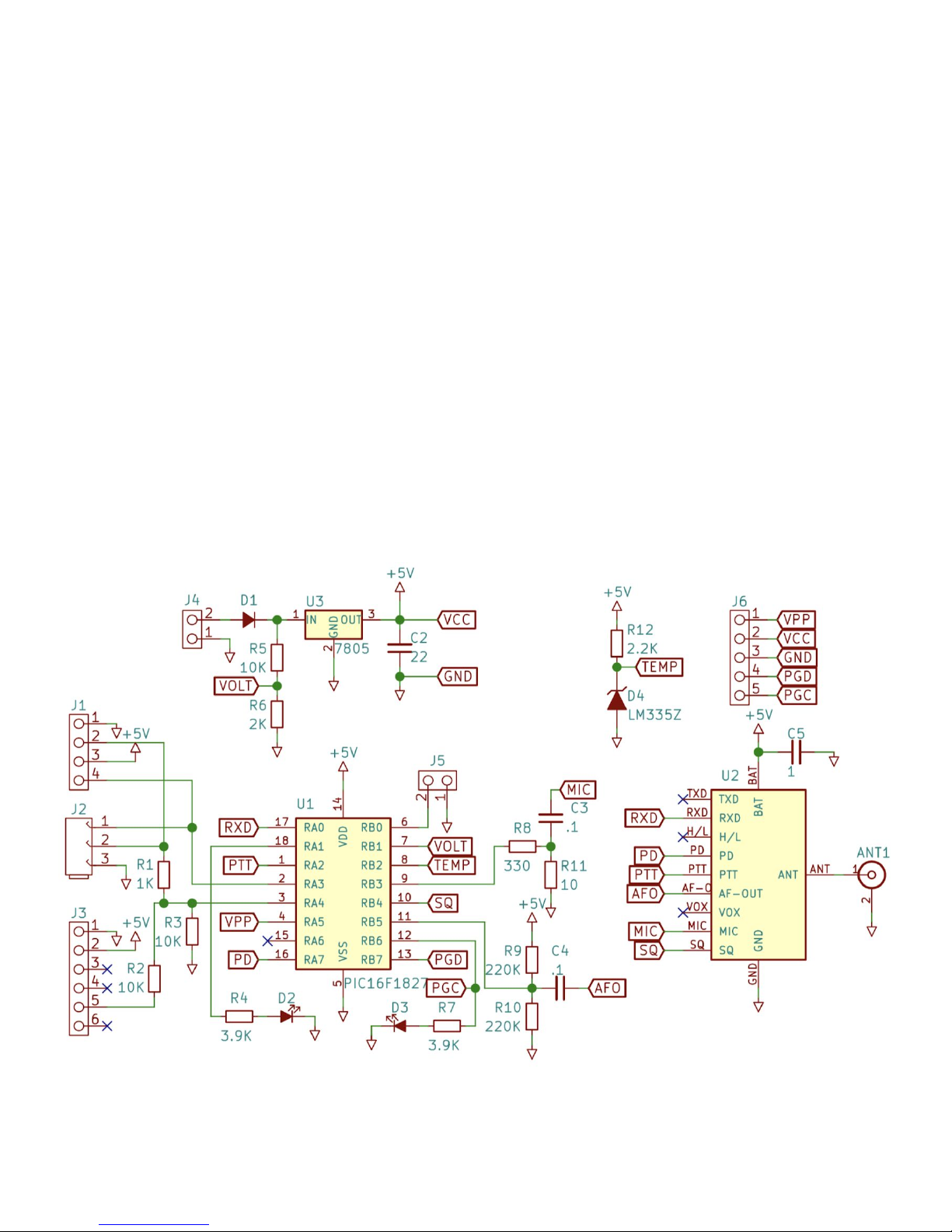
Schematic
Page 3
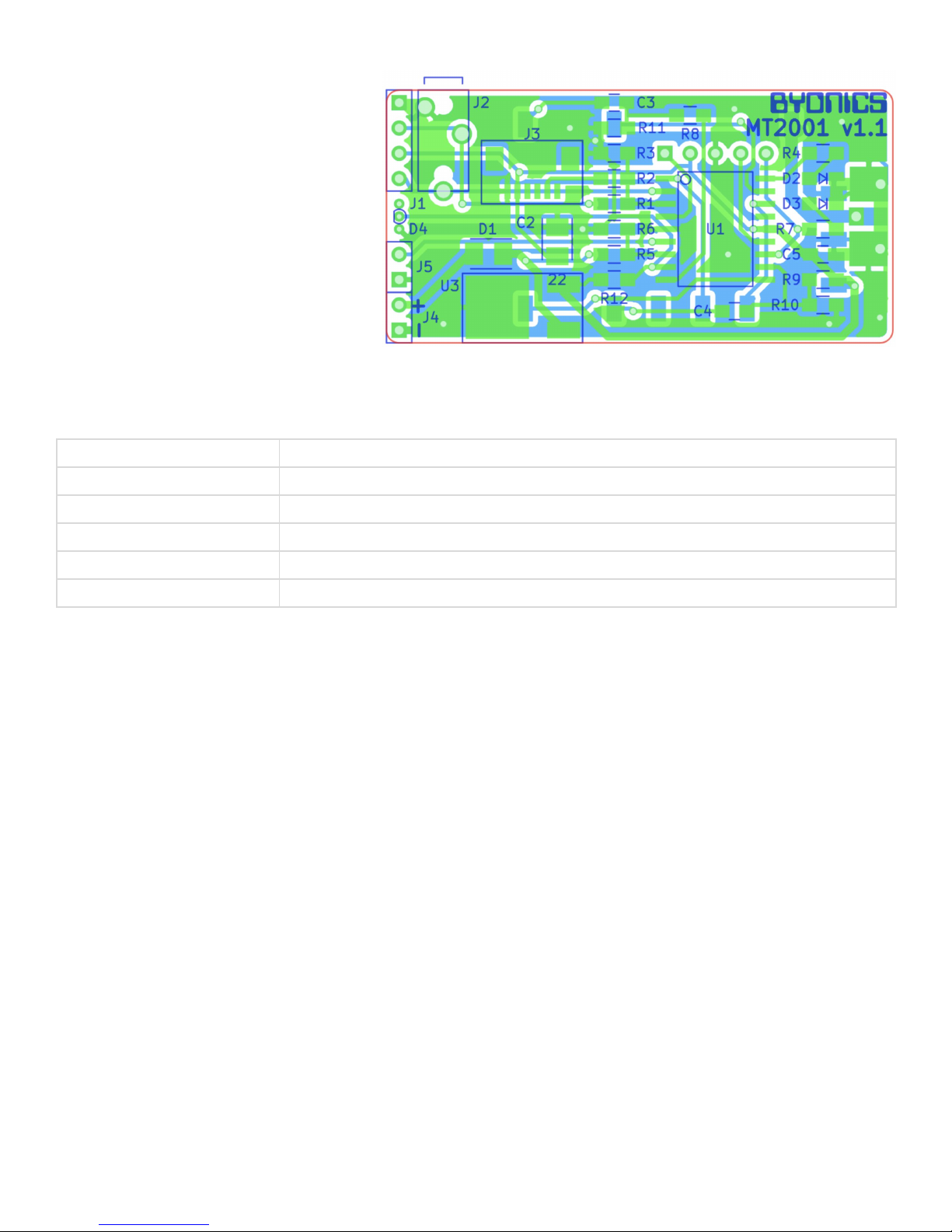
PCB
J1 - Ground, serial in, VCC, serial out
J2 - 2.5mm serial programming jack
J3 - GPS module connection
(tip=serial out, ring=serial in,
sleeve=ground)
J4 - 7-12V DC power input
J5 - Config bank selection switch
Specifications
Size
2.6”x1”x0.25” including RF connector
Supply voltage
7 - 12VDC
Current, standby
20 mA
Current, transmit
780 mA
RF Output
2 Watts @ 9 VDC
Weight
0.4 Ounces
 Loading...