

Page 1
ba75717e01 05/2007
DRAFT: Thursday, 26. April 2007
BYKLC4
Cat. no.: 1740
Operating manual
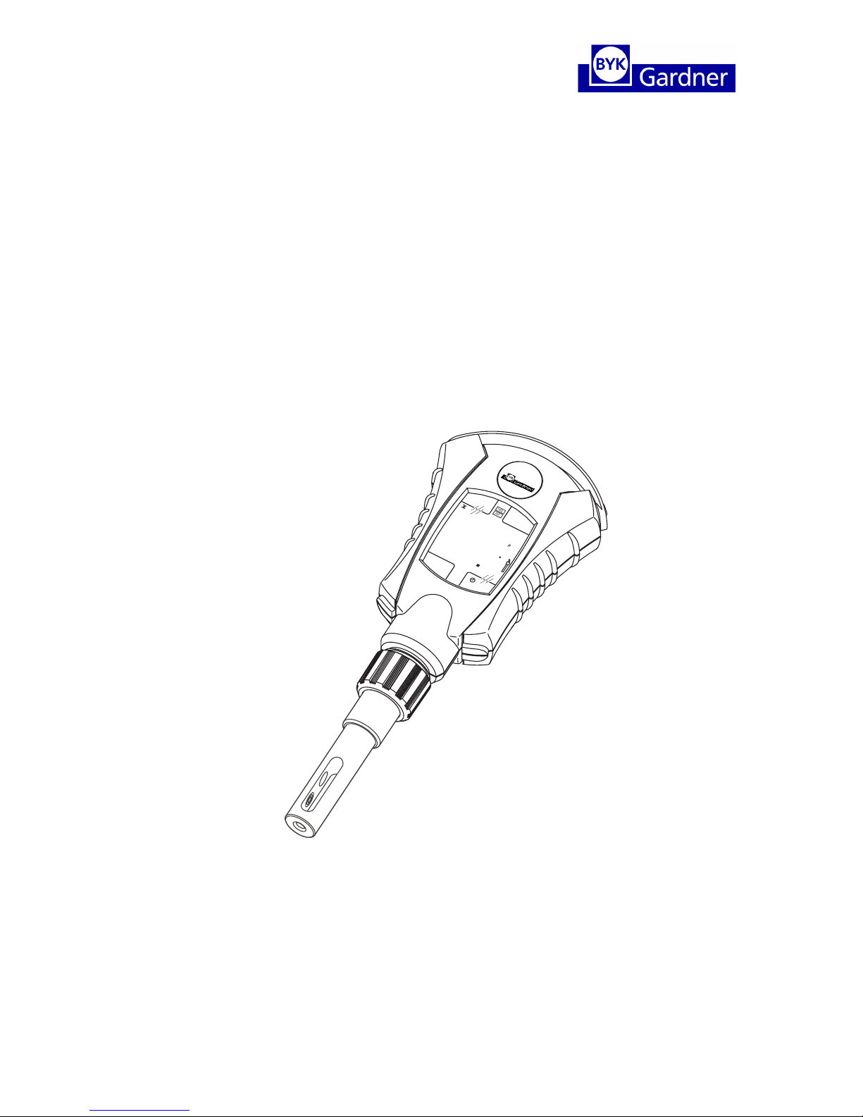
Hand-held conductivity meter
Tr
e
f
2
5
n
L
F
C
A
L
M
E
M
S
/c
m
C
E
S
C
1 3 1 4
2 5 8
BYK LC 4
Page 2

BYK LC 4
2
Accuracy when
going to press
The use of advanced technology and the high quality standard of our
instruments are the result of continuous development. This may result in
differences between this operating manual and your instrument. Also, we
cannot guarantee that there are absolutely no errors in this manual.
Therefore, we are sure you will understand that we cannot accept any legal
claims resulting from the data, figures or descriptions.
Copyright
© Geretsried 2007, BYK-Gardner GmbH
Reprinting - even as excerpts - is only allowed with the explicit written
authorization of BYK-Gardner GmbH, Geretsried.
Printed in Germany.
Page 3

BYKLC4
3
1 Overview . . . . . . . . . . . . . . . . . . . . . . . . . . . . . . . . . . . . . . 5
2 Safety . . . . . . . . . . . . . . . . . . . . . . . . . . . . . . . . . . . . . . . . 7
2.1 Authorized use . . . . . . . . . . . . . . . . . . . . . . . . . . . . . . . . . . . . . 7
2.2 General safety instructions . . . . . . . . . . . . . . . . . . . . . . . . . . . . 8
3 Commissioning . . . . . . . . . . . . . . . . . . . . . . . . . . . . . . . . 9
3.1 Scope of delivery . . . . . . . . . . . . . . . . . . . . . . . . . . . . . . . . . . . . 9
3.2 Initial commissioning . . . . . . . . . . . . . . . . . . . . . . . . . . . . . . . . . 9
3.3 Connecting the sensor module . . . . . . . . . . . . . . . . . . . . . . . . 10
3.4 Storing the meter and sensor module . . . . . . . . . . . . . . . . . . . 11
4 Operation . . . . . . . . . . . . . . . . . . . . . . . . . . . . . . . . . . . . 13
4.1 Operating elements . . . . . . . . . . . . . . . . . . . . . . . . . . . . . . . . . 13
4.2 Switching on the meter . . . . . . . . . . . . . . . . . . . . . . . . . . . . . . 16
4.3 Measuring . . . . . . . . . . . . . . . . . . . . . . . . . . . . . . . . . . . . . . . . 17
4.3.1 General information . . . . . . . . . . . . . . . . . . . . . . . . . . 17
4.3.2 Carrying out measurements . . . . . . . . . . . . . . . . . . . . 18
4.3.3 Setting the TDS factor . . . . . . . . . . . . . . . . . . . . . . . . 19
4.3.4 Switching over the temperature unit . . . . . . . . . . . . . . 20
4.4 Adjusting/calibrating the cell constant . . . . . . . . . . . . . . . . . . . 21
4.4.1 Adjusting the cell constant manually . . . . . . . . . . . . . 22
4.4.2 Determining the cell constant (calibration in the control
standard) . . . . . . . . . . . . . . . . . . . . . . . . . . . . . . . . . . 24
4.5 Setting the temperature compensation . . . . . . . . . . . . . . . . . . 26
4.5.1 Selecting the temperature compensation . . . . . . . . . . 27
4.5.2 Setting the linear temperature coefficient . . . . . . . . . 28
4.6 Setting the reference temperature . . . . . . . . . . . . . . . . . . . . . . 29
4.7 Calibration data . . . . . . . . . . . . . . . . . . . . . . . . . . . . . . . . . . . . 30
4.8 Setting the calibration interval . . . . . . . . . . . . . . . . . . . . . . . . . 31
4.9 Saving . . . . . . . . . . . . . . . . . . . . . . . . . . . . . . . . . . . . . . . . . . . 32
4.9.1 Saving measured data . . . . . . . . . . . . . . . . . . . . . . . . 32
4.9.2 Displaying measured data from the memory . . . . . . . 33
4.9.3 Erasing measured data from the memory . . . . . . . . . 34
4.10 Clock . . . . . . . . . . . . . . . . . . . . . . . . . . . . . . . . . . . . . . . . . . . . 35
4.10.1 Displaying and setting the date and time . . . . . . . . . . 35
4.10.2 Alarm function . . . . . . . . . . . . . . . . . . . . . . . . . . . . . . 37
4.10.3 Stopwatch . . . . . . . . . . . . . . . . . . . . . . . . . . . . . . . . . 38
4.10.4 Timer . . . . . . . . . . . . . . . . . . . . . . . . . . . . . . . . . . . . . 39
4.11 Switch-off interval . . . . . . . . . . . . . . . . . . . . . . . . . . . . . . . . . . 40
4.12 Reset . . . . . . . . . . . . . . . . . . . . . . . . . . . . . . . . . . . . . . . . . . . 41
5 Maintenance, cleaning, disposal . . . . . . . . . . . . . . . . . 43
Page 4

BYK LC 4
4
5.1 Maintenance . . . . . . . . . . . . . . . . . . . . . . . . . . . . . . . . . . . . . . . 43
5.2 Battery exchange . . . . . . . . . . . . . . . . . . . . . . . . . . . . . . . . . . . 43
5.3 Cleaning . . . . . . . . . . . . . . . . . . . . . . . . . . . . . . . . . . . . . . . . . . 44
5.4 Transport . . . . . . . . . . . . . . . . . . . . . . . . . . . . . . . . . . . . . . . . . 45
5.5 Disposal . . . . . . . . . . . . . . . . . . . . . . . . . . . . . . . . . . . . . . . . . . 45
6 What to do if... . . . . . . . . . . . . . . . . . . . . . . . . . . . . . . . . 47
6.1 Processor reset: . . . . . . . . . . . . . . . . . . . . . . . . . . . . . . . . . . . . 48
7 Technical data . . . . . . . . . . . . . . . . . . . . . . . . . . . . . . . . 49
7.1 Measuring instrument . . . . . . . . . . . . . . . . . . . . . . . . . . . . . . . . 49
7.2 Sensor module TetraCon V . . . . . . . . . . . . . . . . . . . . . . . . . . . 52
8 Lists. . . . . . . . . . . . . . . . . . . . . . . . . . . . . . . . . . . . . . . . . 55
9 Index . . . . . . . . . . . . . . . . . . . . . . . . . . . . . . . . . . . . . . . . 59
Page 5
BYKLC4 Overview
5
1 Overview
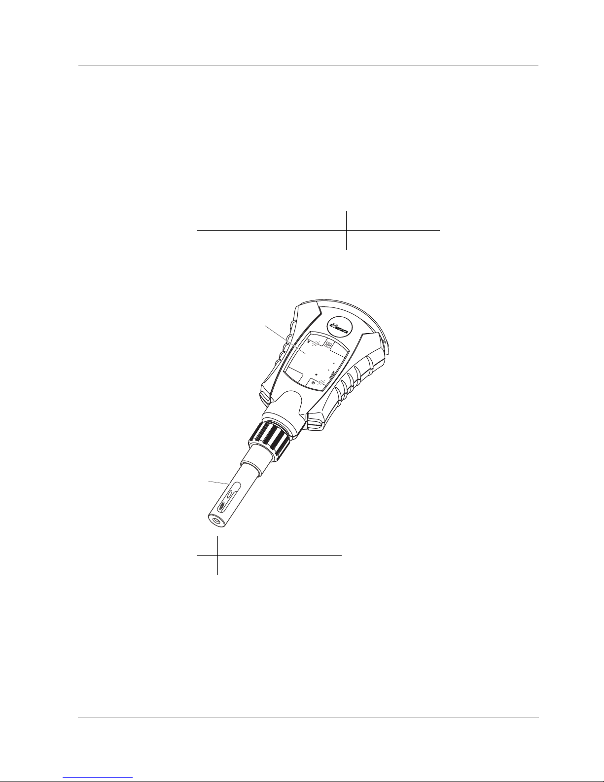
The BYK LC 4 hand-held meter and a suitable sensor module enable you to
measure the conductivity, specific resistance, salinity or TDS (total dissolved
solids) of a solution very easily.
Depending on the measuring range expected, the following sensor modules
are suitable for operation with the BYK LC 4 hand-held meter.
All functions and settings are operated via the touch screen.
Measuring range Sensor module
1 µS/cm ... 200 mS/cm TetraCon V
1 Display (touch screen)
2 Sensor module
Tr
e
f
2
5
nLF
C
A
L
M
E
M
S/cm
C
ESC
1 3 1 4
2 5 8
1
2
B
Y
K
L
C
4
Page 6

Overview BYK LC 4
6
Page 7
BYKLC4 Safety
7
2Safety
This operating manual contains basic instructions that you must follow during
the commissioning, operation and maintenance of the meter. Consequently,
all responsible personnel must read this operating manual before working
with the meter. The operating manual must always be available within the
vicinity of the meter.
User qualification The meter was developed for work in the laboratory.
We assume that, as a result of their professional training and experience, the
operators will know the necessary safety precautions to take when handling
chemicals.
Safety
instructions
The individual chapters of this operating manual use safety instructions such
as the label shown below to indicate various hazards or dangers:
Caution
indicates instructions that must be followed precisely in order to avoid
the possibility of slight injuries or damage to the instrument or the environment.
Further notes
Note
indicates notes that draw your attention to special features.
Note
indicates cross-references to other documents, e.g. operating manuals.
2.1 Authorized use
The authorized use of the meter consists exclusively of the measurement of
the conductivity, salinity, temperature and TDS (total dissolved solids).
The technical specifications as given in chapter 7 T
ECHNICAL DATA must be
observed. Only the operation and running of the meter according to the
instructions given in this operating manual is authorized.
Any other use is considered to be unauthorized.
Page 8

Safety BYK LC 4
8
2.2 General safety instructions
This instrument is built and inspected according to the relevant guidelines
and norms for electronic meters (see chapter 7 T
ECHNICAL DATA).
It left the factory in a safe and secure technical condition.
Function and
operating safety
The smooth functioning and operational safety of the meter can only be guaranteed if the generally applicable safety measures and the specific safety
instructions in this operating manual are followed during operation.
The smooth functioning and operational safety of the meter can only be guaranteed under the environmental conditions that are specified in chapter 7
T
ECHNICAL DATA.
If the instrument was transported from a cold environment to a warm environment, the formation of condensate can lead to the faulty functioning of the
instrument. In this event, wait until the temperature of the instrument reaches
room temperature before putting the instrument back into operation.
Safe operation If safe operation is no longer possible, the instrument must be taken out of
service and secured against inadvertent operation!
Safe operation is no longer possible if the meter:
! has been damaged in transport
! has been stored under adverse conditions for a lengthy period of time
! is visibly damaged
! no longer operates as described in this manual.
If you are in any doubt, please contact the supplier of the instrument.
Obligations of the
purchaser
The purchaser of this meter must ensure that the following laws and guidelines are observed when using dangerous substances:
! EEC directives for protective labor legislation
! National protective labor legislation
! Safety regulations
! Safety datasheets of the chemical manufacturers.
Page 9

BYKLC4 Commissioning
9
3 Commissioning
3.1 Scope of delivery
! BYK LC 4 hand-held meter
! Sensor module (TetraCon V)
! Accompanying documents:
– Manual for commissioning
– Short instructions to be glued in the lid of the case
– CD-ROM with a description of all instrument functions
! Transport case with insert
3.2 Initial commissioning
Perform the following activities:
! Connect the sensor module to the meter (see section 3.3)
! Switch on the meter (see section 4.2)
! Set the date and time (see section 4.10.1)
! Calibrate the meter with the sensor module (see section 4.4)
Page 10
Commissioning BYK LC 4
10
3.3 Connecting the sensor module
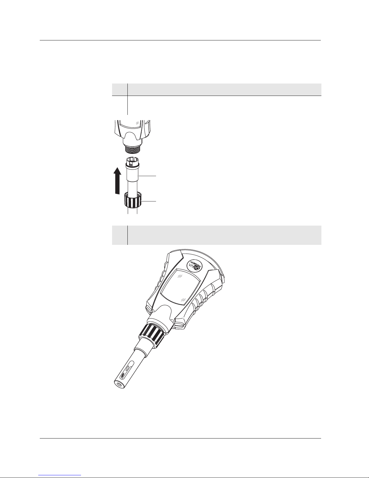
1 Unscrew the coupling ring (1) from the meter.
2 Place the sensor module (2) in a straight position to the meter (turn
the wide cut-out to the front) and plug it in carefully with slight force.
3 Using the coupling ring (1), screw the sensor module tight.
The instrument is ready for operation.
1
2
Page 11

BYKLC4 Commissioning
11
3.4 Storing the meter and sensor module
To maintain the operability of the meter and sensor module for a long time,
leave the sensor module connected to the meter as possible and avoid to
plug it on or off when it is not necessary. Thus, the watertight plug-in
connector will be well protected.
In order to store an already used sensor module separately from the meter,
protect the socket of the sensor module with the original protective cap.
Page 12

Commissioning BYK LC 4
12
Page 13
BYKLC4 Operation
13
4 Operation
4.1 Operating elements
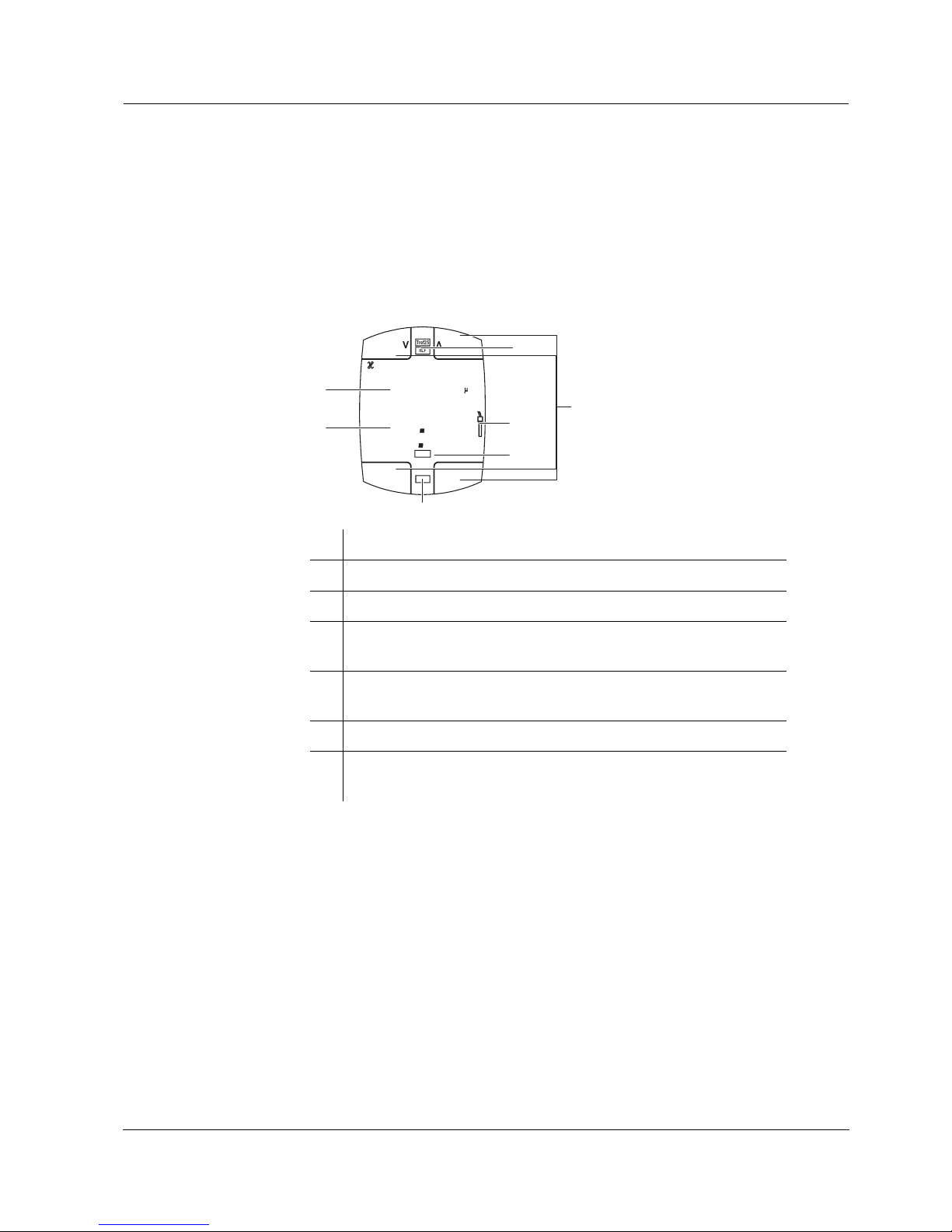
The entire operation is carried out via the touch sensitive surface of the
display (touch screen). A slight pressure on the surface suffices to start a
function. Any pressure on the surface is confirmed by an acoustic signal.
Display elements
1 Upper display line - example: stored conductivity value
2 Lower display line - example: storing time
3 Function keys
4 Status display indicators on the current function of the meter:
Example: r = read out memory
5 Additional information
Example: h = unit of the indication in the second line
6 Sensor symbol
7 Status display of stored measuring data
Example: Tref25, nLF
C
MEM
CAL
TDS
CellTC
S
SAL
O
2
TC
RESET
Cell
LAP
m
mbar
mg/l
CAL
STO
LoBat
Day.Month
min:s
Ident
Lap
Lin
Tref20Tref20
M
cm
k
cm
Sal
1
cm
K
Tref25
nLF
S/cm
ESC
1 3 1 4
5 5 8
RCL
1
CLR
h:min
3
1
2
6
4
5
7
Page 14
Operation BYK LC 4
14
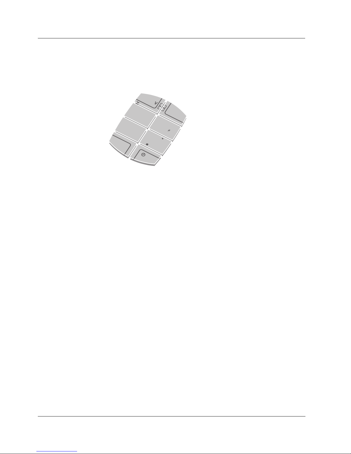
Touch screen The touch screen contains 8 touch sensitive tactile areas that start different
functions when being pressed, depending on the operating situation.
The function of the keys is connected to the display indication in this area.
m
Tre
f25
n
L
F
CAL
M
EM
S/cm
C
ESC
1 3 1 4
2 5 8
Tre
f25
n
L
F
MEMMEM
1 3 1
m
S/cm
C
2 5
ESC
Tre
f25
n
L
F
CAL
Tre
f25
n
L
F
MEMMEM
1 3 1
m
MEMMEM
S/cm
1 3
2 5
m
S/
C
1 4
ESC
2
8
Page 15

BYKLC4 Operation
15
Touch screen
operation
In this operating manual, keys are indicated by angle brackets <..>.
The touch screen symbol (example <3>) shows you which area you have
to press. Function keys are indicated by the relevant name or symbol.
The keys can have different functions with a long and short keystroke.
In this operating manual, the key symbol (e. g. <E>) generally means a
short keystroke (shorter than 1 sec). A long keystroke (approx. 1 sec) is indicated by a line after the key symbol (e. g. <E_>).
Operating examples:
Note
Any keystroke is confirmed by an acoustic signal.
With a short keystroke you hear a short sound, after a long keystroke you
hear a longer sound.
Symbol Meaning
<(> Press any spot on the display shortly.
(Example: switch on the meter)
<"_> Press any key in the upper display line for a
longer time (approx. 1 sec).
(Example: switch over the measured value
display between conductivity, specific resistance etc.)
<C> Press "CAL" shortly.
<U> Press the "Clock symbol" shortly.
<E_> Press "ESC" for a longer time (approx. 1 sec).
(Example: switch off the meter)
<<> or <>> Press <<> or <>> shortly.
Increase or reduce the displayed value by 1.
<<_> or <>_> Press <<> or <>> for a longer time (approx.
1sec).
Increase or reduce the displayed value
consecutively.
Page 16
Operation BYK LC 4
16
4.2 Switching on the meter
Note
The meter has an energy saving feature to avoid unnecessary battery depletion. The energy saving feature switches the meter off if no entry is made
during the specified switch off-interval (see section 4.11).
1 Switch on the meter with <(>.
After a short display test, a measured value is displayed.
If no sensor module is connected, the Err4 error message appears
on the display (see chapter 6 W
HAT TO DO IF...).
Page 17
BYKLC4 Operation
17
4.3 Measuring
4.3.1 General information
Depth of
immersion
For measurements in a measuring solution we recommend an immersion
depth of approx. 36 mm for optimum and reproducible measurement results.
The sensor module may only be submersed in a measuring solution up to
below the coupling ring. If it is submersed deeper, liquid can penetrate the
meter and damage it.
AutoRead
(drift control)
The AutoRead function (drift control) checks the stability of the measurement
signal. The stability has a considerable impact on the reproducibility of
measured values. The AutoRead function is automatically active. The unit of
the measured value flashes on the display as long as the stability criterion is
not met. A stable measured value is achieved when the unit of the measured
parameter no longer flashes.
Temperature
compensation
The meter has a linear and nonlinear temperature compensation (see section
4.5 S
ETTING THE TEMPERATURE COMPENSATION). The temperature compensa-
tion can be switched off.
Reference
temperature Tref
The reference temperature (Tref) can be switched over between 20 °C and
25 °C. It appears on the display as Tref20 or Tref25. To switch over the reference temperature, see section 4.6 S
ETTING THE REFERENCE TEMPERATURE.
Caution
Special measuring media (e.g. strong acids and lyes, organic solvents) or too
high temperatures shorten the lifetime considerably or cause damage. The
warranty does not cover damage caused by such measuring media and
mechanical damage.
Page 18
Operation BYK LC 4
18
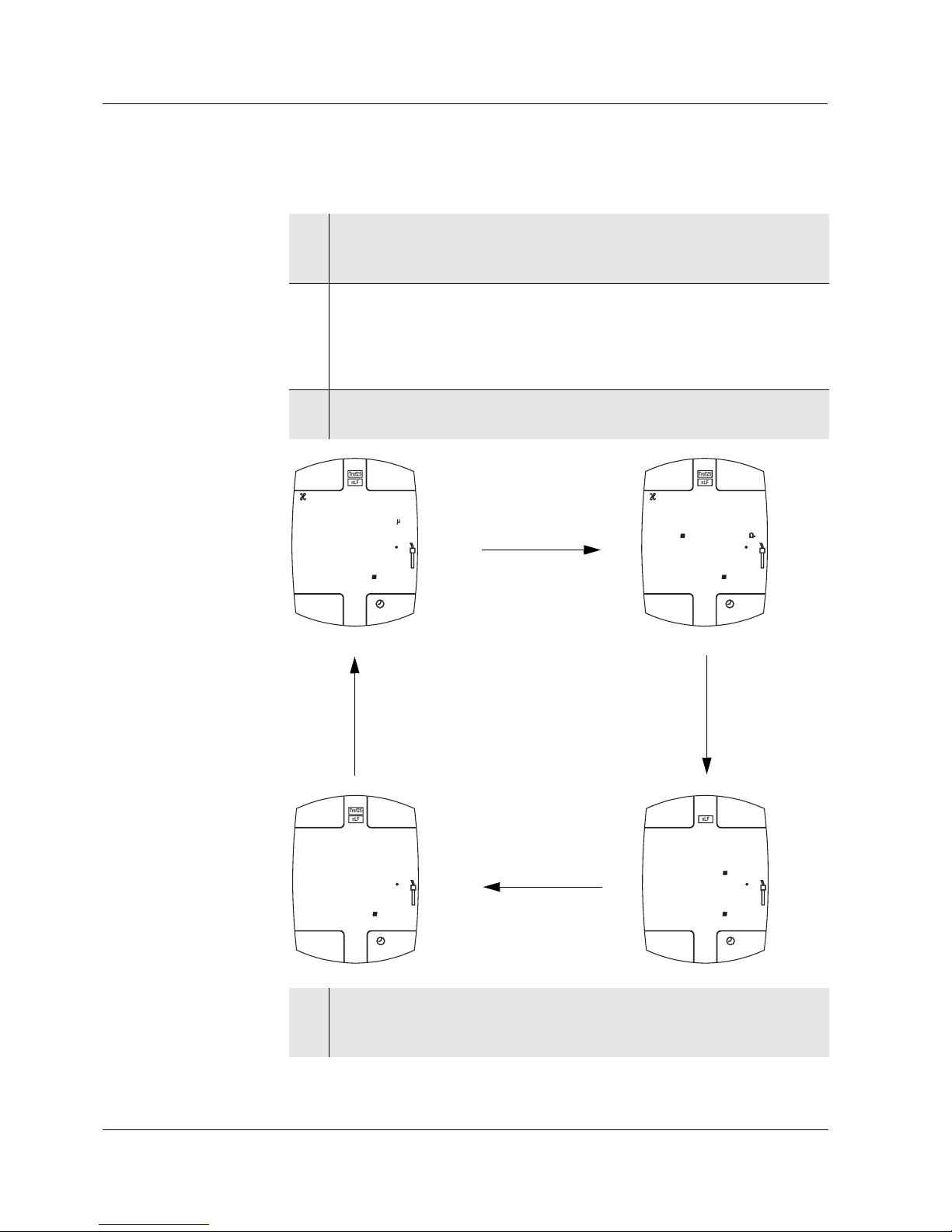
4.3.2 Carrying out measurements
Setting menu,
measured
parameter
1 Make sure a valid calibration exists for the measuring system (see
section 4.4.2), or that the cell constant is correctly adjusted (see
section 4.4.2).
2 Immerse the sensor module in the test sample.
The display shows the main measured value (conductivity, specific
resistance, salinity or TDS) and the measured temperature value.
The unit of the measured value display flashes (AutoRead) as long
as the measured value is not stable.
3 If necessary, switch over the display between conductivity, specific
resistance, salinity and TDS with <"_> [<Measured value>].
4 Wait for a stable measured value.
As soon as the measured value is stable, the unit of the measured
parameter no longer flashes.
RCL
TDS
CellTC
S
SAL
O
2
TC
RESET
Cell
LAP
m
mbar
mg/l
CAL
STO
LoBat
Day.Month
h:min min:s
Ident
Lap
8
CLR
Lin
Tref20Tref20
M
cm
k
cm
Sal
1
cm
K
Tref25
nLF
CAL
MEM
S/cm
C
ESC
1 3 1 4
2 5 8
M
cm
S
mS/cm
RCL
TDS
CellTC
SAL
O
2
TC
RESET
Cell
LAP
mbar
mg/l
CAL
STO
LoBat
Day.Month
h:min min:s
Ident
Lap
8
CLR
Lin
Tref20Tref20
Sal
1
cm
K
Tref25
nLF
CAL
MEM
C
ESC
0 7 6 1
2 5 8
k
cm
<"_>
mS/cm
RCL
CellTC
S
SAL
O
2
TC
RESET
Cell
LAP
mbar
CAL
STO
LoBat
Day.Month
h:min min:s
Ident
Lap
8
CLR
Lin
Tref20Tref20
M
cm
k
cm
Sal
1
cm
K
Tref25
nLF
CAL
MEM
C
ESC
3 1 4
2 5 8
TDS
mg/l
1 3
Tref25
1
S/cm
RCL
TDS
CellTC
S
O
2
TC
RESET
Cell
LAP
m
mbar
mg/l
CAL
STO
LoBat
Day.Month
h:min min:s
Ident
Lap
8
CLR
Lin
Tref20Tref20
M
cm
k
cm
Sal
1
cm
K
nLF
CAL
MEM
C
ESC
0 2
2 5 8
SAL
<"_>
<"_>
<"_>
Page 19
BYKLC4 Operation
19
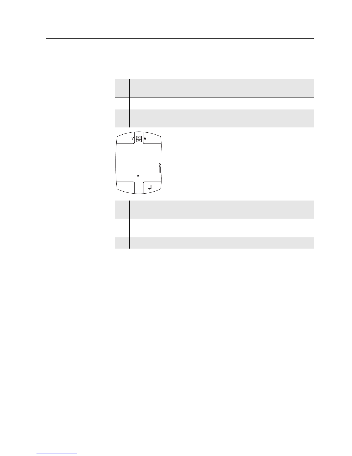
4.3.3 Setting the TDS factor
1 If necessary, press <"_> [<Measured value>] repeatedly until the
measured parameter TDS is displayed (see section 4.3.2).
2 Using <ß> [<Temperature>], display the adjusted TDS factor.
3 Using <ß> [<TDS factor>], select the TDS factor.
The TDS factor flashes.
4 Using <<> or <>>, set the TDS factor (0.40 ... 1.00).
The measured TDS value display is always updated while doing so.
5 Confirm the TDS factor with <g>.
The TDS factor no longer flashes.
6 Using <ß> [<TDS factor>], display the measured temperature value.
MEM
CAL
C
mS/cm
RCL
CellTC
S
SAL
O
2
TC
RESET
Cell
LAP
mbar
CAL
STO
LoBat
Day.Month
h:min min:s
Ident
Lap
8
CLR
Lin
Tref20Tref20
M
cm
k
cm
Sal
1
cm
K
Tref25
nLF
ESC
3 1 4
1 0 8
TDS
mg/l
1
Page 20
Operation BYK LC 4
20
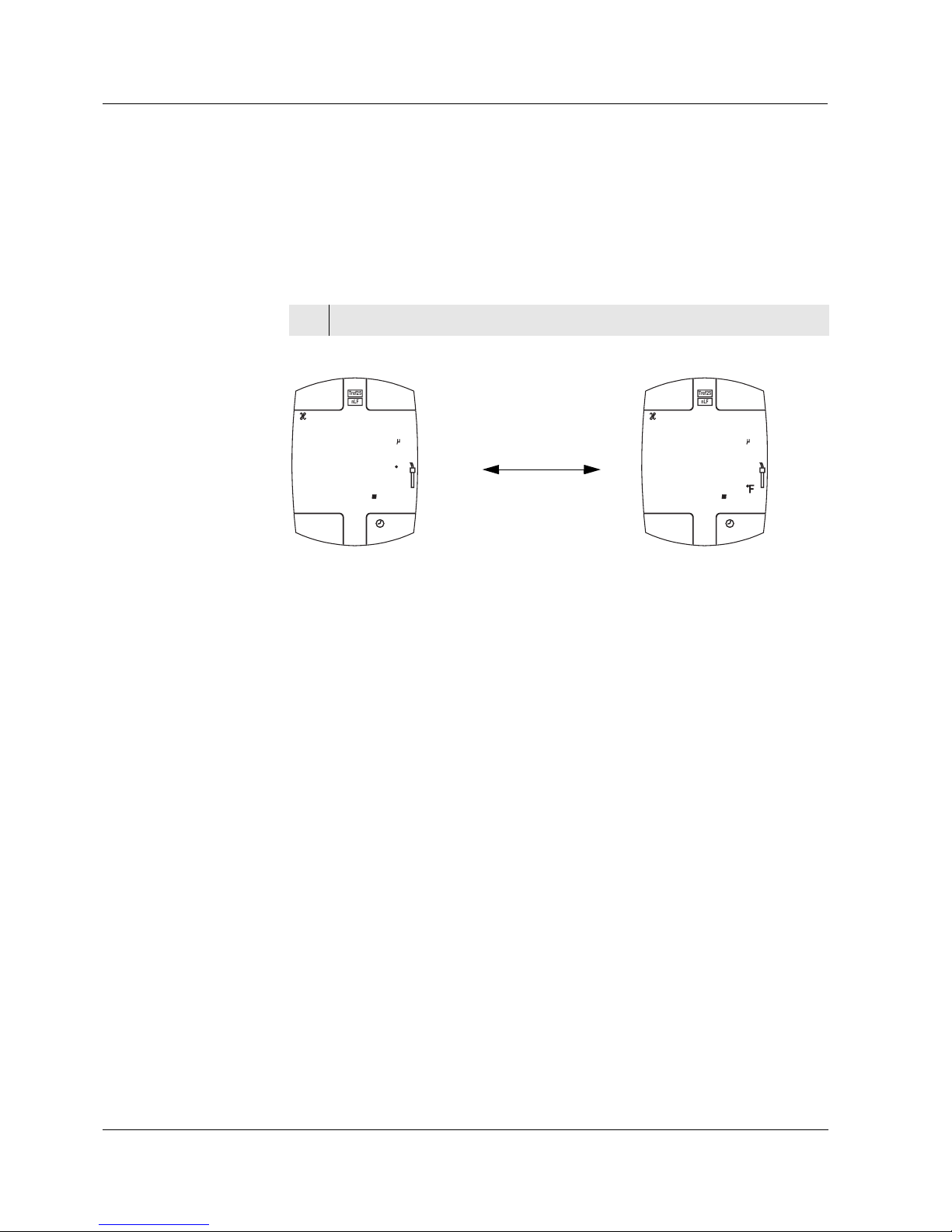
4.3.4 Switching over the temperature unit
For reproducible conductivity measurements, it is essential to measure the
temperature of the test sample. A temperature sensor is integrated in the
sensor module.
You can switch the temperature display from °C to °F:
Setting menu of
the temperature
unit
1 Toggle the display between °C and °F with <ß_> [<Temperature>].
RCL
TDS
CellTC
S
SAL
O
2
TC
RESET
Cell
LAP
m
mbar
mg/l
CAL
STO
LoBat
Day.Month
h:min min:s
Ident
Lap
8
CLR
Lin
Tref20Tref20
M
cm
k
cm
Sal
1
cm
K
Tref25
nLF
CAL
MEM
S/cm
C
ESC
1 3 1 4
2 5 8 7
C
RCL
TDS
CellTC
S
SAL
O
2
TC
RESET
Cell
LAP
m
mbar
mg/l
CAL
STO
LoBat
Day.Month
h:min min:s
Ident
Lap
CLR
Lin
Tref20Tref20
M
cm
k
cm
Sal
1
cm
K
Tref25
nLF
CAL
MEM
S/cm
ESC
1 3 1 4
7 8 4
<ß_>
Page 21

BYKLC4 Operation
21
4.4 Adjusting/calibrating the cell constant
Why adjust/
calibrate the cell
constant?
The actual cell constant of the sensor module can slightly differ from the
nominal value of the cell constant.
Depending on the required measuring accuracy, you can measure with the
nominal value of the cell constant that was set in the factory (see chapter
7T
ECHNICAL DATA), or adjust the value of the cell constant.
You have the following options to adjust the value of the cell constant:
! (Determining and) Adjusting the cell constant manually
The cell constant can be adjusted in the following ranges:
! Calibrating the cell constant (automatic determination)
This method can be selected for the TetraCon V sensor module (range
that can be calibrated: 0.450 ... 0.500 cm
-1
).
Calibration is carried out in the 0.01 mol/l KCl control standard.
Cell constants outside the above mentioned ranges cannot be adjusted or
calibrated.
Both the calibration data and the value of the manually adjusted cell constant
are stored in the sensor module and can be selected and used for measurements.
Note
Aging slightly changes the characteristics of the cell, e. g. by coatings. As a
result, an inexact measured value is displayed. The original characteristics of
the cell can often be restored by cleaning the cell.
When to adjust/
calibrate the cell
constant?
! If the measuring accuracy with the nominal value of the cell constant that
was set in the factory does not suffice (see chapter 7 T
ECHNICAL DATA)
! After the calibration interval has expired (when the sensor symbol flashes)
Calibration interval The interval for the determination of the cell constant is set to 180 days in the
factory. You can select the interval in the range of 1 ... 999 days (see section
4.8).
You should calibrate at regular intervals (we recommend: every 6 months).
– TetraCon V 0.450 ... 0.500 cm
-1
Page 22
Operation BYK LC 4
22
AutoRead
(drift control)
The calibration procedure automatically activates the AutoRead function.
The display of the unit flashes during the AutoRead measurement.
The current AutoRead measurement can be terminated at any time (without
accepting the current value) by pressing <E>.
Calibration data The calibration data is stored in the sensor module. It contains the value of
the determined cell constant. The value of the determined cell constant is
displayed after a valid calibration and is accessible any time.
Calibration status The meter has a simple display of the calibration status.
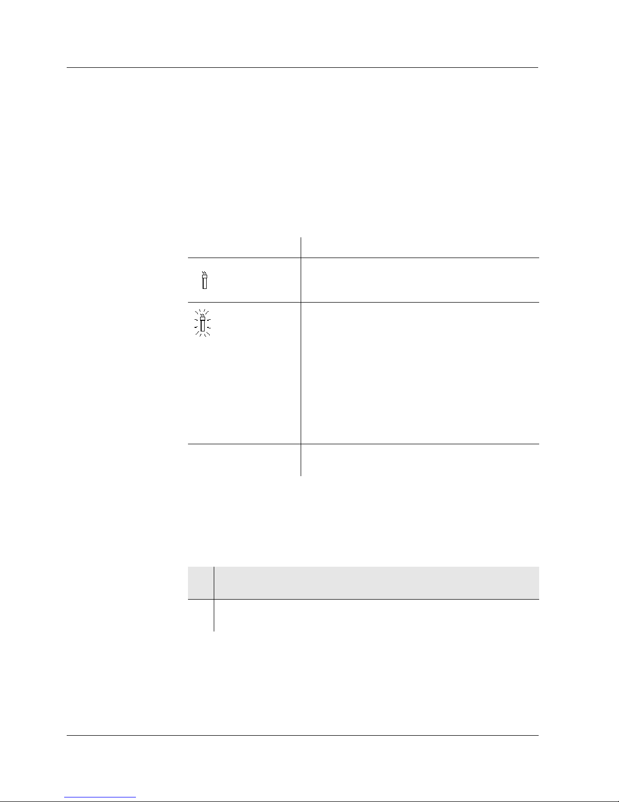
4.4.1 Adjusting the cell constant manually
You can adjust the cell constant manually as follows:
Display indication Calibration status
A valid calibration is available.
flashes
Prompt to calibrate or adjust the cell constant. It is
still possible to measure.
Causes:
– The calibration interval has expired
– The cell constant that can be calibrated was
reset to the delivery condition (e. g. after a
reset)
– The last calibration was erroneous (error
message, Err3)
No sensor symbol on
the display.
The meter measures with an adjusted cell
constant
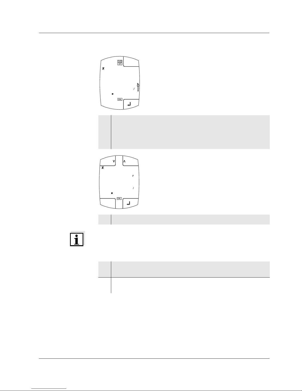
1 Open the setting menu for the cell constant with <C>.
The display shows the setting last selected.
2 If necessary, press <"_> repeatedly until the CELL display
appears.
Page 23
BYKLC4 Operation
23
Note
You can terminate the setting of the cell constant with <E>.
The data of the terminated setting is not used.
The cell constant adjusted before remains active.
3 Confirm the displayed cell constant with g .
The displayed cell constant is used immediately.
or
Select the cell constant setting with <ß_>.
The cell constant flashes.
4 Adjust the cell constant with <<> or <>>.
5 Confirm the adjusted cell constant with g .
The cell constant no longer flashes.
6 Return to the measuring mode with <g>.
The adjusted cell constant is used.
Cell
LAP
CAL
ESC
TC
MEM
RESET
Sal
mg/l
Lin
Tref20Tref20
TDS
C
mS/cm
RCL
S
SAL
O
2
mbar
STO
LoBat
Day.Month
h:min min:s
Ident
Lap
CLR
M
cm
k
cm
K
E LC
CAL
TC
Cell
7 80 4
1
cm
Tref25
nLF
L
TC
Sal
mg/l
Lin
Tref20Tref20
Tref25
nLF
TDS
MEM
CAL
C
m
RCL
S
SAL
O
2
TC
RESET
Cell
LAP
mbar
STO
LoBat
Day.Month
h:min min:s
Ident
Lap
CLR
M
cm
k
cm
K
ESC
4 91
CAL
Cell
4 8 10
1
cm
3
S/cm
Page 24
Operation BYK LC 4
24
4.4.2 Determining the cell constant (calibration in the control standard)
Note
This method of automatically determining the cell constant by calibration in
the 0.01 mol/l KCL control standard solution can only be used for measuring
cells with cell constants in the range 0.450 ... 0.500 cm
-1
(sensor module
TetraCon V).
This is how you can determine the cell constant:
Note
You can return to the measuring mode with <g>.
The displayed calibrated cell constant is used immediately.
Note
You can terminate the calibration with <E>.
The data of the terminated calibration is not used.
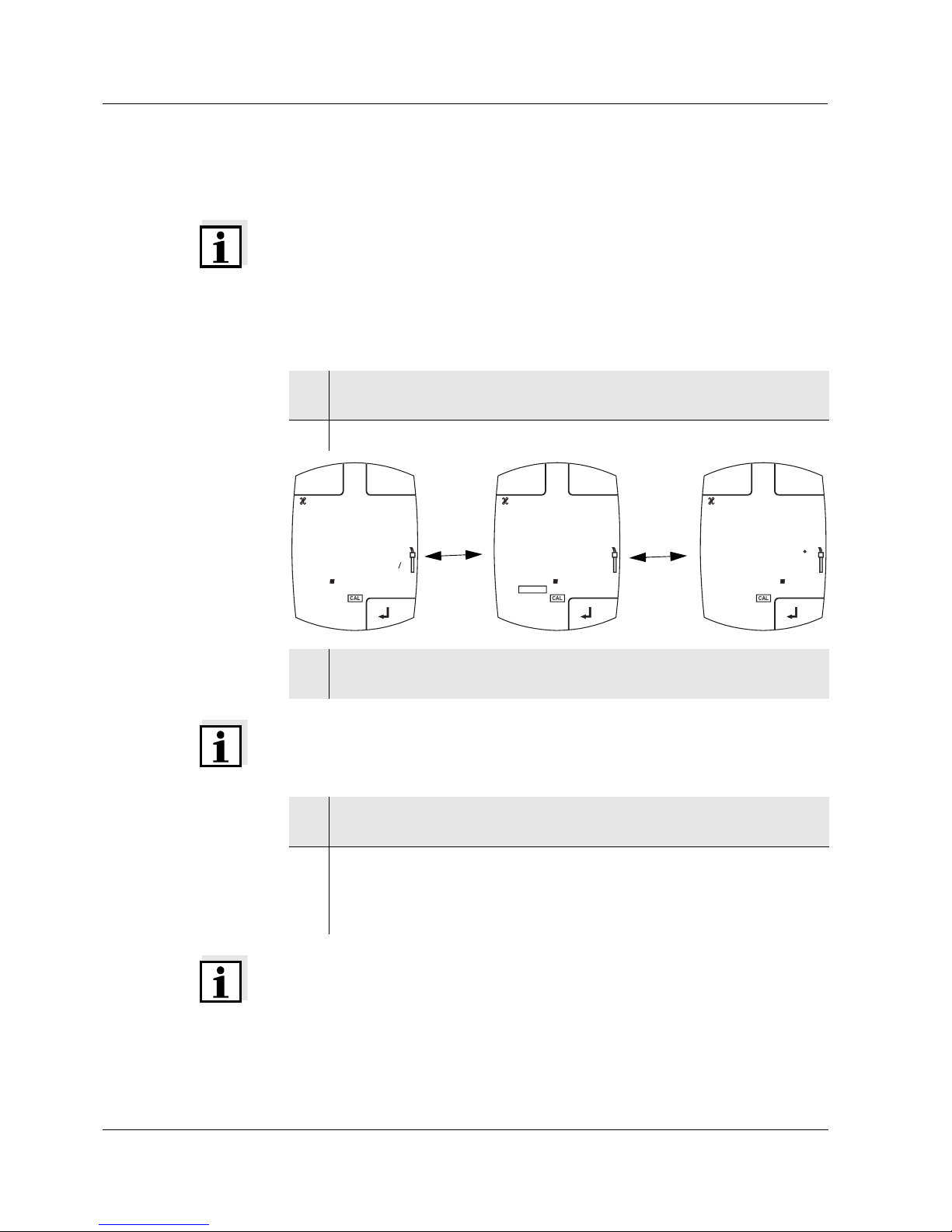
1 Open the setting menu for the cell constant with <C>.
The display shows the setting last selected.
2 If necessary, press <"_> repeatedly until the CAL display appears.
3 If necessary, switch between the cell constant last calibrated, the
date of the calibration and the calibration temperature with <ß>.
4 To calibrate:
Immerse the sensor module in the control standard solution.
5 Start the measurement with <C>.
The calibrated cell constant is displayed.
The unit of the measured value display flashes (AutoRead) as long
as the measured value is not stable.
ESC
TC
Sal
4
mg/l
Lin
Tref20Tref20
Tref25
nLF
TDS
MEM
C
mS/cm
RCL
S
SAL
O
2
RESET
Cell
LAP
mbar
STO
LoBat
Day.Month
h:min min:s
Ident
Lap
CLR
M
cm
k
cm
K
A LC
CAL
Cell
4 6 80
1
cm
CAL
TC
ESC
CellTC
Sal
4
mg/l
Lin
Tref20Tref20
Tref25
nLF
TDS
MEM
C
mS/cm
RCL
S
SAL
O
2
RESET
Cell
LAP
mbar
STO
LoBat
h:min min:s
Ident
Lap
CLR
M
cm
k
cm
1
cm
K
A LC
CAL
Day.Month
1 3 0 5
CAL
TC
<ß_>
ESC
Day.Month
1
CellTC
Sal
4
mg/l
Lin
Tref20Tref20
Tref25
nLF
TDS
MEM
mS/cm
RCL
S
SAL
O
2
RESET
Cell
LAP
mbar
STO
LoBat
h:min min:s
Ident
Lap
CLR
M
cm
k
cm
1
cm
K
A LC
CAL
2 5 7
CAL
TC
C
<ß_>
Page 25
BYKLC4 Operation
25
Note
If no valid calibration can be accomplished, the Err3 error message appears
on the display. Measuring is not possible in this condition. Possible causes
and actions for error elimination can be found in chapter 6 W
HAT TO DO IF....
6 Wait until the measured value is stable.
The unit of the measured value display stops flashing.
7 Return to the measuring mode with <g>.
The calibrated cell constant is used.
Page 26
Operation BYK LC 4
26
4.5 Setting the temperature compensation
The calculation of the temperature compensation is based on the preset
reference temperature, Tref20 or Tref25 (see section 4.6 S
ETTING THE REFER-
ENCE TEMPERATURE).
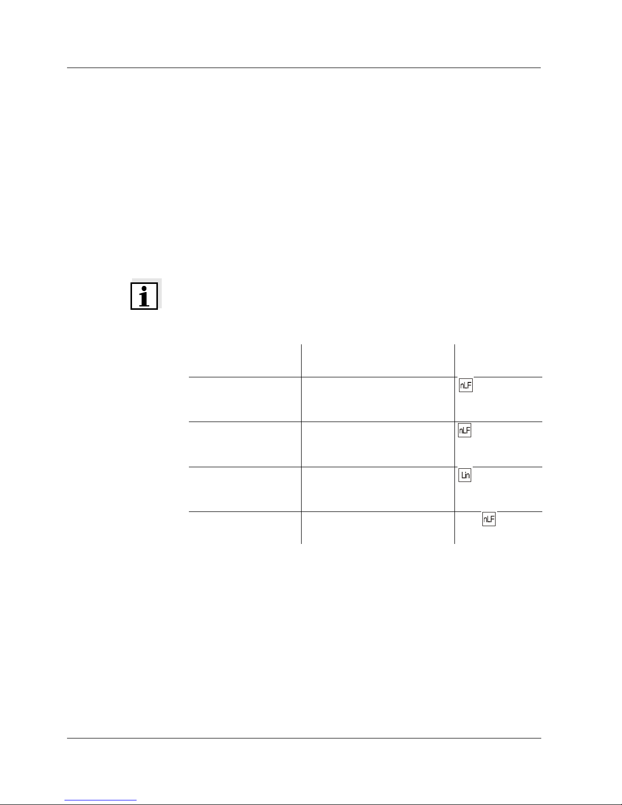
You can select one of the following temperature compensation methods:
! Nonlinear temperature compensation (nLF)
! Linear temperature compensation (Lin) with selectable coefficients of
0.001 ... 3.000 %
/K
! No temperature compensation (- - - -)
Note
Select the following temperature compensations given in the table according
to the respective test sample:
Application tips
Measuring solution Temperature compensation
(TC)
Display
indicator
Natural water (ground
water, surface water
and drinking water)
nLF
according to ISO 7888, EN
27888
(*)
(*) Corresponds to DEV C8
Ultrapure water nLF
according to ISO 7888, EN
27888
(*)
Other aqueous solutions
Set linear
temperature coefficient 0.001
... 3.000 %/K
Salinity
(seawater)
Automatic nLF according to
IOT
Sal,
Page 27
BYKLC4 Operation
27
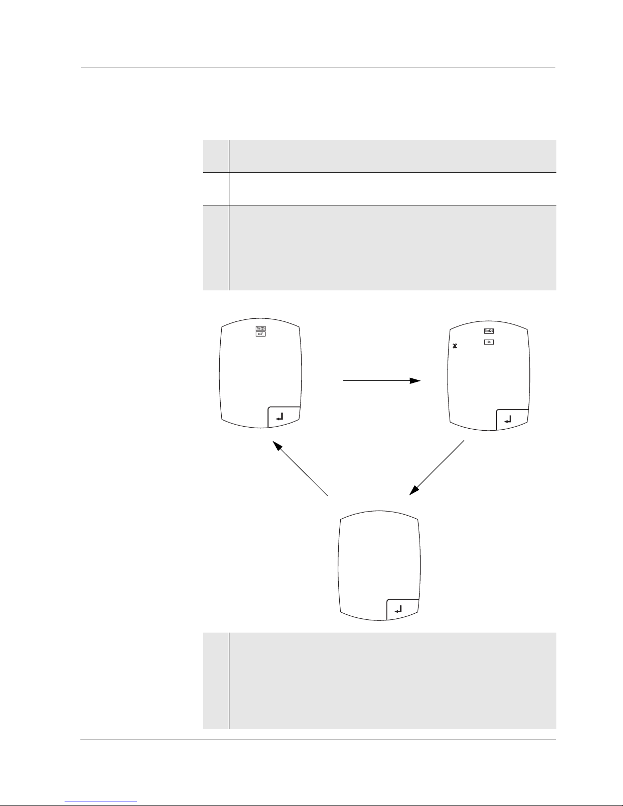
4.5.1 Selecting the temperature compensation
Setting menu for
the temperature
compensation
1 Open the setting menu for the cell constant with <C>.
The display shows the setting last selected.
2 Open the setting menu for the temperature compensation with <T>.
The display shows the setting last selected.
3 If necessary, press <ß_> repeatedly until the nLF, Lin or OFF display
appears.
– nLF = nonlinear temperature compensation
– Lin = linear temperature compensation
– OFF = temperature compensation switched off
4 – Confirm the setting with <g>.
in the nLF menu --> back to the measuring mode
–in the Lin menu --> the menu for setting the temperature coef-
ficient opens up (see section 4.5.2)
–in the OFF menu --> back to the measuring mode
The displayed setting is used immediately.
CAL
ESC
S/cm
K
2
Cell
1
cm
Sal
mg/l
Tref20Tref20
nLF
TDS
MEM
CAL
C
m
RCL
S
SAL
O
2
TC
RESET
Cell
LAP
mbar
STO
LoBat
Day.Month
h:min min:s
Ident
Lap
CLR
M
cm
k
cm
r 2t
L i n
5
Tref25
TC
Lin
<ß_>
ESC
CAL
S/cm
02rt
Tref25
Cell
Lin
1
cm
0
Sal
mg/l
Tref20Tref20
nLF
TDS
MEM
CAL
C
m
RCL
S
SAL
O
2
TC
RESET
Cell
LAP
mbar
STO
LoBat
Day.Month
h:min min:s
Ident
Lap
CLR
M
cm
k
cm
K
O F F
TC
<ß_>
<ß_>
S/cm
CAL
ESC
Lin
Cell
1
cm
0
Sal
mg/l
Tref20Tref20
TDS
MEM
CAL
C
m
RCL
S
SAL
O
2
TC
RESET
Cell
LAP
mbar
STO
LoBat
Day.Month
h:min min:s
Ident
Lap
CLR
M
cm
k
cm
K
r 2t
n L F
5
Tref25
TC
nLF
Page 28
Operation BYK LC 4
28
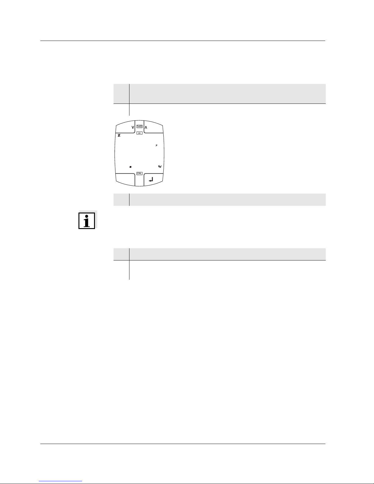
4.5.2 Setting the linear temperature coefficient
Note
You can terminate the setting of the temperature coefficient with <E>.
The data of the terminated setting is not used.
The temperature coefficient set before remains active.
1 Select the linear temperature compensation (Lin menu) (see section
4.5.1).
2 Open the setting of the linear temperature coefficient with <ß>.
3 Set the temperature coefficient with <<> or <>>.
4 Confirm the adjusted value with <g>.
5 Return to the measuring mode with <g>.
The adjusted temperature coefficient is used.
Cell
1
cm
Sal
mg/l
Tref20Tref20
nLF
TDS
MEM
CAL
C
m
RCL
S
SAL
O
2
TC
RESET
Cell
LAP
mbar
STO
LoBat
Day.Month
h:min min:s
Ident
Lap
CLR
M
cm
k
cm
ESC
3 81
CAL
1 1 8
7
S/cm
Tref25
TC
2
K
Lin
Page 29
BYKLC4 Operation
29
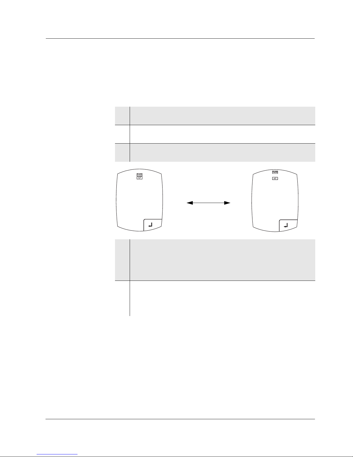
4.6 Setting the reference temperature
The setting is only effective if the linear or nonlinear temperature compensation is switched on.
You can set the reference temperature as follows:
Setting menu of
the reference
temperature
1 Open the setting menu for the cell constant with <C>.
The display shows the setting last selected.
2 Open the setting menu for the temperature compensation with <T>.
The display shows the setting last selected.
3 If necessary, select the nLF or Lin temperature compensation with
<ß_>.The display shows the reference temperature set last.
4 Using <"_>, switch between tr20 and tr25.
– tr20 = reference temperature 20 °C
– tr25 = reference temperature 25 °C
The adjusted reference temperature is used.
5 Confirm the setting with <g>.
–in the nLF menu --> back to the measuring mode
–in the Lin menu --> the menu for setting the temperature coef-
ficient opens up (see section 4.5.2)
<ß_>
S/cm
CAL
ESC
Lin
Cell
1
cm
0
Sal
mg/l
Tref20Tref20
TDS
MEM
CAL
C
m
RCL
S
SAL
O
2
TC
RESET
Cell
LAP
mbar
STO
LoBat
Day.Month
h:min min:s
Ident
Lap
CLR
M
cm
k
cm
K
r 2t
n L F
5
Tref25
TC
nLF
Tref25
S/cm
CAL
ESC
Lin
Cell
1
cm
0
Sal
mg/l
TDS
MEM
CAL
C
m
RCL
S
SAL
O
2
TC
RESET
Cell
LAP
mbar
STO
LoBat
Day.Month
h:min min:s
Ident
Lap
CLR
M
cm
k
cm
K
r 2t
n L F
0
TC
nLF
Tref20Tref20
Page 30
Operation BYK LC 4
30
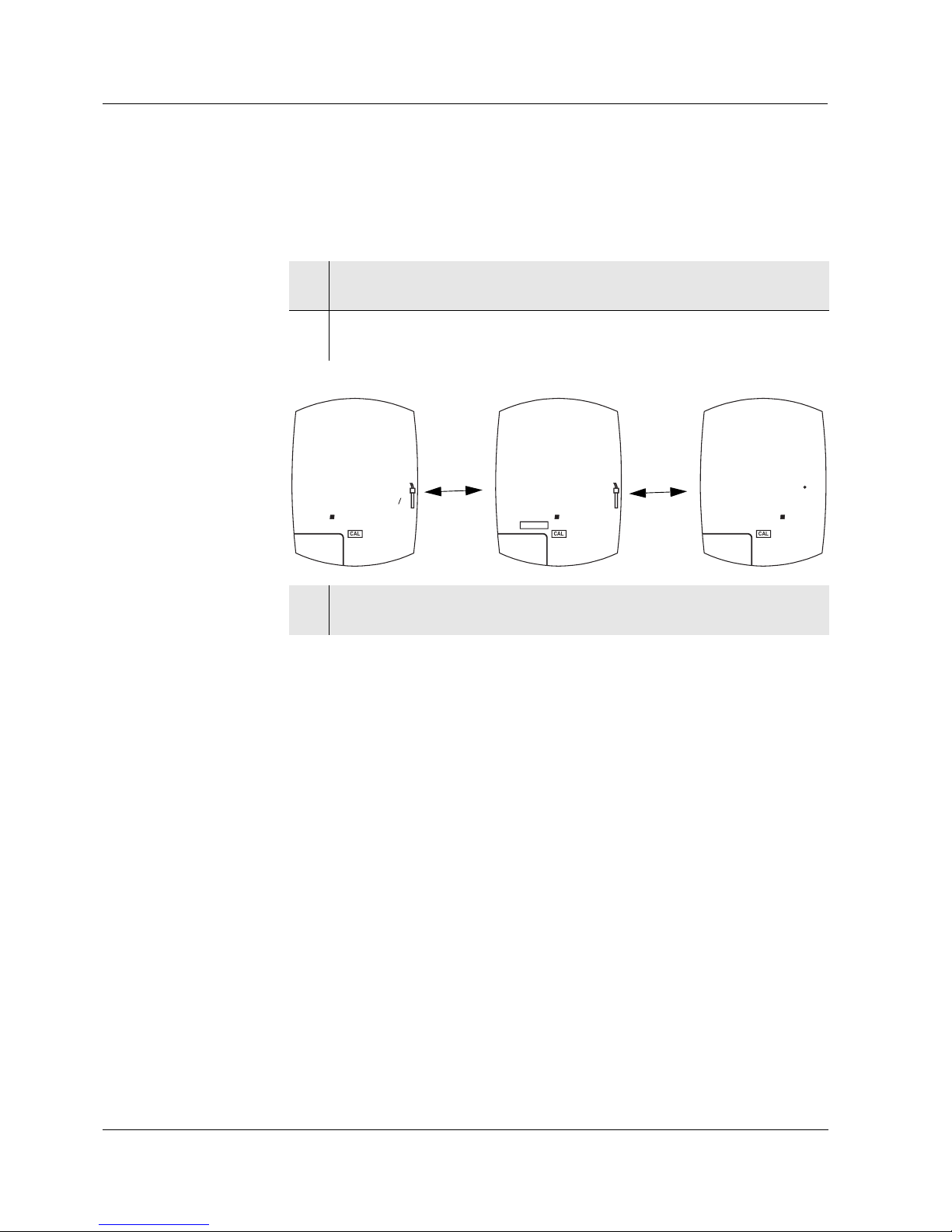
4.7 Calibration data
The calibrated cell constant is displayed after calibration (see section 4.4.2)
and is accessible any time.
1 Switch on the meter with <(>.
The display test is displayed.
2 During the display test:
Display the calibrated cell constant with <C>.
3 If necessary, switch between the cell constant last calibrated, the
date of the calibration and the calibration temperature with <ß_>.
TC
Day.Month
Sal
4
mg/l
Lin
Tref20Tref20
Tref25
nLF
TDS
MEM
CAL
C
mS/cm
RCL
S
SAL
O
2
TC
RESET
Cell
LAP
mbar
STO
LoBat
h:min min:s
Ident
Lap
CLR
M
cm
k
cm
K
ESC
A LC
CAL
0 4 6 8
1
cm
Cell
<ß_>
1
Day.Month
CellTC
Sal
4
mg/l
Lin
Tref20Tref20
Tref25
nLF
TDS
MEM
CAL
mS/cm
RCL
S
SAL
O
2
TC
RESET
Cell
LAP
mbar
STO
LoBat
h:min min:s
Ident
Lap
CLR
M
cm
k
cm
1
cm
K
ESC
A LC
CAL
2 5 7
C
<ß_>
CellTC
Sal
4
mg/l
Lin
Tref20Tref20
Tref25
nLF
TDS
MEM
CAL
C
mS/cm
RCL
S
SAL
O
2
TC
RESET
Cell
LAP
mbar
STO
LoBat
h:min min:s
Ident
Lap
CLR
M
cm
k
cm
1
cm
K
ESC
A LC
CAL
Day.Month
1 3 0 5
Page 31
BYKLC4 Operation
31
4.8 Setting the calibration interval
The calibration interval determines how many days after the last calibration
the instrument should remind you to recalibrate.
The sensor symbol on the display flashes when the calibration interval has
expired.
1 Open the Init initialization menu with <C_>.
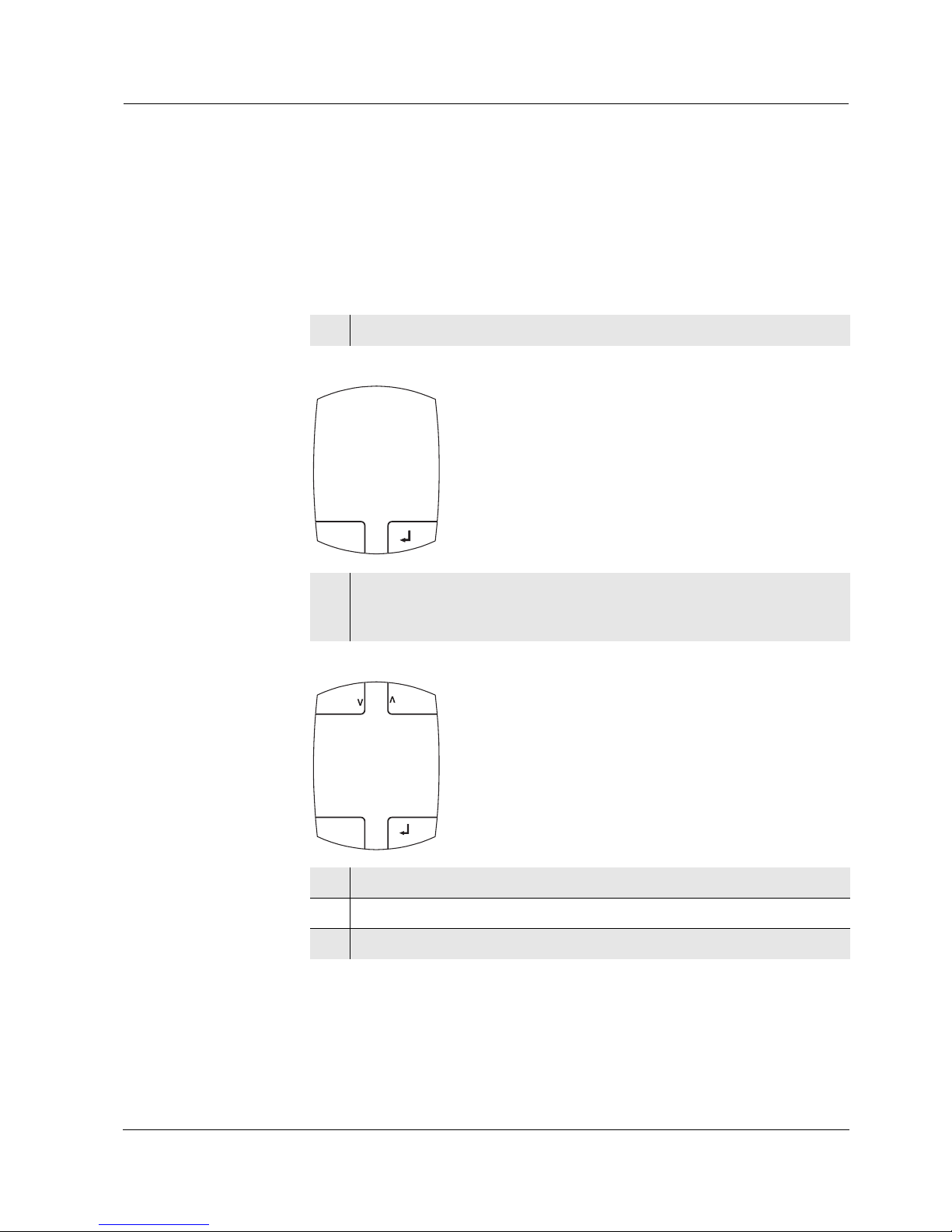
2 Press <g> to confirm NO for the initialization.
The setting of the calibration interval is displayed.
The display flashes.
3 Set the calibration interval in days (d) with <<> and <>>.
4 Confirm the setting with <g>.
5 Switch to the measuring mode with <g>.
STO
Y
RCL
C
S/cm
Tref25
nLF
MEM
CAL
TDS
CellTC
S
SAL
O
2
TC
RESET
Cell
LAP
m
mbar
mg/l
CAL
LoBat
Day.Month
h:min min:s
Ident
Lap
8
CLR
Lin
Tref20Tref20
M
cm
k
cm
Sal
1
cm
K
ESC
1 n i t
n o
Day.Month
MEM
CAL
d
C
pH
8
LoBat
min:s
Ident
Lap
mV
h:min
CLR
RESET
LAP
ESC
I n t
08d
1
Page 32
Operation BYK LC 4
32
4.9 Saving
The BYK LC 4 meter has a data memory. Up to 50 measurement datasets
can be stored in it.
A dataset consists of:
! Main measured value (conductivity, specific resistance, salinity or TDS)
! Measured temperature value
! Time and date
! ID number (0000 - 9999)
4.9.1 Saving measured data
You can save measured data as follows:
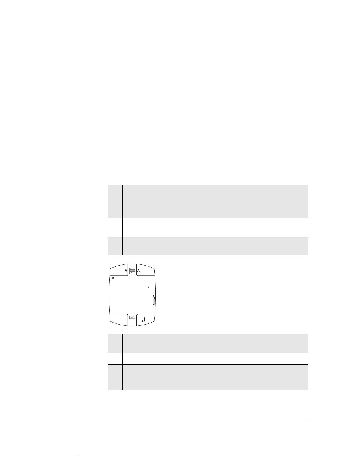
1 Open the save menu with <M>.
The memory number of the next free memory location is displayed
under the current measured value.
The X status indicator appears.
2 Switch to the display of the ID number with <g>.
The ID number that was last entered appears on the display.
3 If necessary, edit the four-digit ID number with <5_> and <6_>
[<ID number>].
4 Using <<> and <>>, enter the required ID number (0 ... 9999).
The selected display flashes.
5 Confirm the ID number with <g>.
6 Save the measurement dataset with <g>.
or
Cancel the storing procedure without storing by pressing <E>.
C
MEM
CAL
RCL
TDS
CellTC
S
SAL
O
2
TC
RESET
Cell
LAP
m
mbar
mg/l
CAL
LoBat
Day.Month
h:min min:s
Ident
Lap
CLR
Lin
Tref20Tref20
M
cm
k
cm
Sal
1
cm
K
S/cm
ESC
1 3 1 4
0 0 10
Tref25
nLF
STO
Page 33
BYKLC4 Operation
33
If all storage locations are occupied, the StoFull message appears. You have
the following options:
4.9.2 Displaying measured data from the memory
Stored measurement datasets always have the main measured value in the
upper display line and a variable display of further elements of the measurement dataset in the lower line.
Display stored datasets as follows:
Save the current measured value.
The oldest measured value (storage location 1)
will be overwritten by this
Press <g>
Return to the measuring mode without saving Press <E>
Erase the entire memory See section 4.9.3
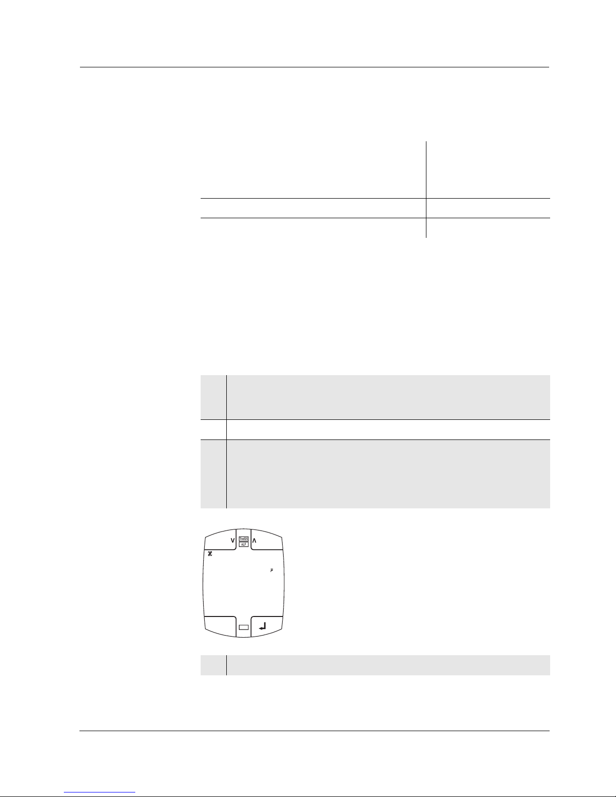
1 Display the memory with <M_>.
The W status indicator appears on the display.
The measurement dataset that was saved last is displayed.
2 Scroll through the stored datasets with <<> and <>>.
3 If necessary, display further elements of the dataset (ID number,
date, time, temperature) with <ß_> [element of the measurement
dataset].
When scrolling further, this element is displayed in the second line
together with the measured value.
4 Scroll through the stored datasets with <<> <>>.
52
C
MEM
CAL
TDS
CellTC
S
SAL
O
2
TC
RESET
Cell
LAP
m
mbar
mg/l
CAL
STO
LoBat
Day.Month
h:min min:s
Ident
Lap
CLR
Lin
Tref20Tref20
M
cm
k
cm
Sal
1
cm
K
Tref25
nLF
S/cm
ESC
1 3 1 4
1n
RCL
Page 34
Operation BYK LC 4
34
4.9.3 Erasing measured data from the memory
To erase all datasets proceed as follows:
5 If necessary, display further elements of the dataset (ID number,
date, time, temperature) with <ß_> [element of the measurement
dataset].
6 Switch to the measuring mode with <E>.
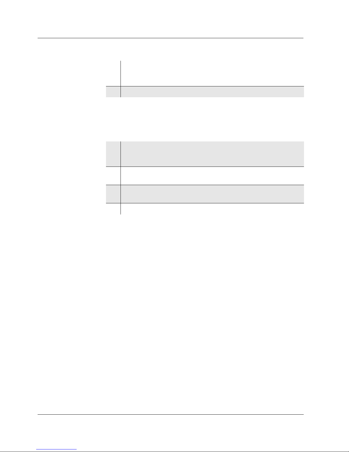
1 Display the memory with <M_>.
The W status indicator appears on the display.
The measured value that was saved last is displayed.
2 Erase the entire memory with <D>.
A security prompt appears.
3 Confirm the deletion with <g>.
After the deletion, NO DATA appears on the display.
4 Switch to the measuring mode with <E>.
Page 35
BYKLC4 Operation
35
4.10 Clock
The meter has a clock.
When saving measured values and calibrating, the date and current time are
automatically saved as well.
The clock has the following additional functions:
! Alarm function (see section 4.10.2).
! Stopwatch (see section 4.10.3) and
! Timer (see section 4.10.4).
Note
The automatic switch-off (section 4.11) is not activated as long as the clock
is indicated on the display.
4.10.1 Displaying and setting the date and time
The correct setting of the date and time is important for the following functions
and displays:
! Current date and time
! Calibration date
! Alarm function
! Identification of stored measured values.
Therefore, check the time regularly.
Note
The date and time are reset to 01.01.2004, 00:00 hours with a battery
change. Set the clock after each battery change.
Setting the date
and time
1 Switch on the meter with <(>.
After a short display test, a measured value is displayed.
2Press <U> to indicate the time and date on the display.
The v status indicator appears.
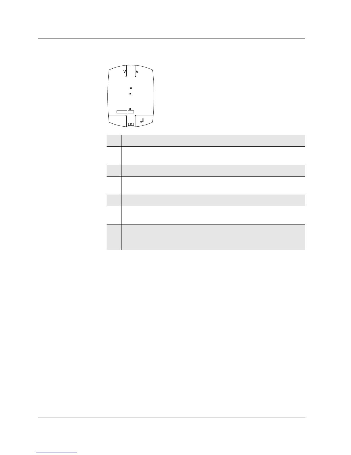
3 Select the hours or minutes with <3_> or <4_> [<Hours> or
<Minutes>].
The h symbol flashes.
Page 36
Operation BYK LC 4
36
4 Set the time with <>> and <<>.
5 Select the [<Day> or <Month>] with <5_> or <6_>.
The d symbol flashes.
6 Set the date with <>> and <<>.
7 Confirm the setting with <g>.
The year is displayed.
8 Set the year with <>> and <<>.
9 Confirm the setting with <g>.
The time and date are displayed again.
10 Switch to the measured value display with <E>.
or
Set the alarm time (see section 4.10.2).
C
S/cm
MEM
nLF
Tref25
CAL
RCL
TDS
CellTC
S
SAL
O
2
TC
RESET
Cell
LAP
m
mbar
mg/l
CAL
STO
LoBat
min:s
Ident
Lap
CLR
Lin
Tref20Tref20
M
cm
k
cm
Sal
1
cm
K
ESC
1 1 0 9
3 0 5
Day.Month
h:min
1
Page 37
BYKLC4 Operation
37
4.10.2 Alarm function
With the alarm function you set a point of time (alarm time) at which an alarm
signal should sound. Prerequisite is the correct setting of the time (see
section 4.10.1).
The alarm signal also sounds when the meter is switched off.
Setting the alarm
time
1 Switch on the meter with <(>.
After a short display test, a measured value is displayed.
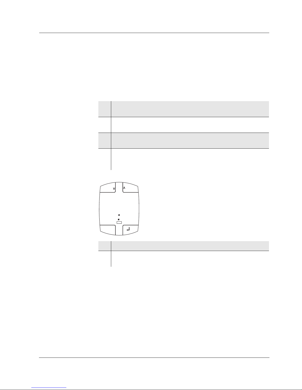
2Press <U> to indicate the time and date on the display.
The v status indicator appears.
3 Indicate the alarm time with <U>.
The alarm time appears on the display.
4 Select the hours or minutes with <5_> or <6_> [<Hours> or
<Minutes>].
The selected display flashes.
5 Set the alarm time with <>> and <<>.
6 Confirm with <g>.
The alarm time is set.
CLR
Ident
C
pH
mV
d
Day.Month
MEM
CAL
LoBat
min:s
Lap
RESET
LAP
ESC
00
-
A L -
00
h:min
Page 38
Operation BYK LC 4
38
Switching on the
alarm function
Switching off the
alarm function
4.10.3 Stopwatch
With the stopwatch, you measure time periods of up to 59:59
(minutes:seconds). In the case of longer periods the stopwatch starts
counting at 00:00 again.
7 Switch to the date and time display with <g>.
The alarm function is switched on. The v status indicator flashes.
or
Switch to the date and time display with <E>.
The alarm time is stored. The alarm function is switched off.
8 When the alarm time is due and the alarm function is switched on, an
alarm signal can be heard for one minute and the measured value
display flashes.
Switch off the alarm signal with <(>.
9 Switch to the date and time display with <g>.
The alarm function is switched off.
1 Display the alarm time (see above).
2 Switch off the alarm function with <E>.
The display shows the date and time.
The alarm function is switched off.
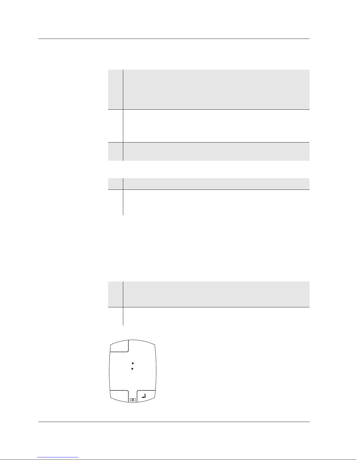
1 Display the stopwatch with <U_>.
The v status indicator appears.
The stopwatch is on 00:00.
2 Start the stopwatch with <g>.
The stopwatch starts counting the seconds.
S/cm
RCL
C
5 82
CAL
MEM
nLF
Tref25
TDS
CellTC
S
SAL
O
2
TC
RESET
Cell
m
mbar
mg/l
CAL
STO
LoBat
Day.Month
h:min min:s
Ident
Lap
8
CLR
Lin
Tref20Tref20
M
cm
k
cm
Sal
1
cm
K
ESC
0 0 0 9
LAP
Page 39
BYKLC4 Operation
39
4.10.4 Timer
The timer function can count down the seconds of a specified time interval
(timer intervall) of maximum 59:59 (minutes:seconds). When the specified
timer interval has expired, an alarm signal sounds for one minute and the
display flashes.
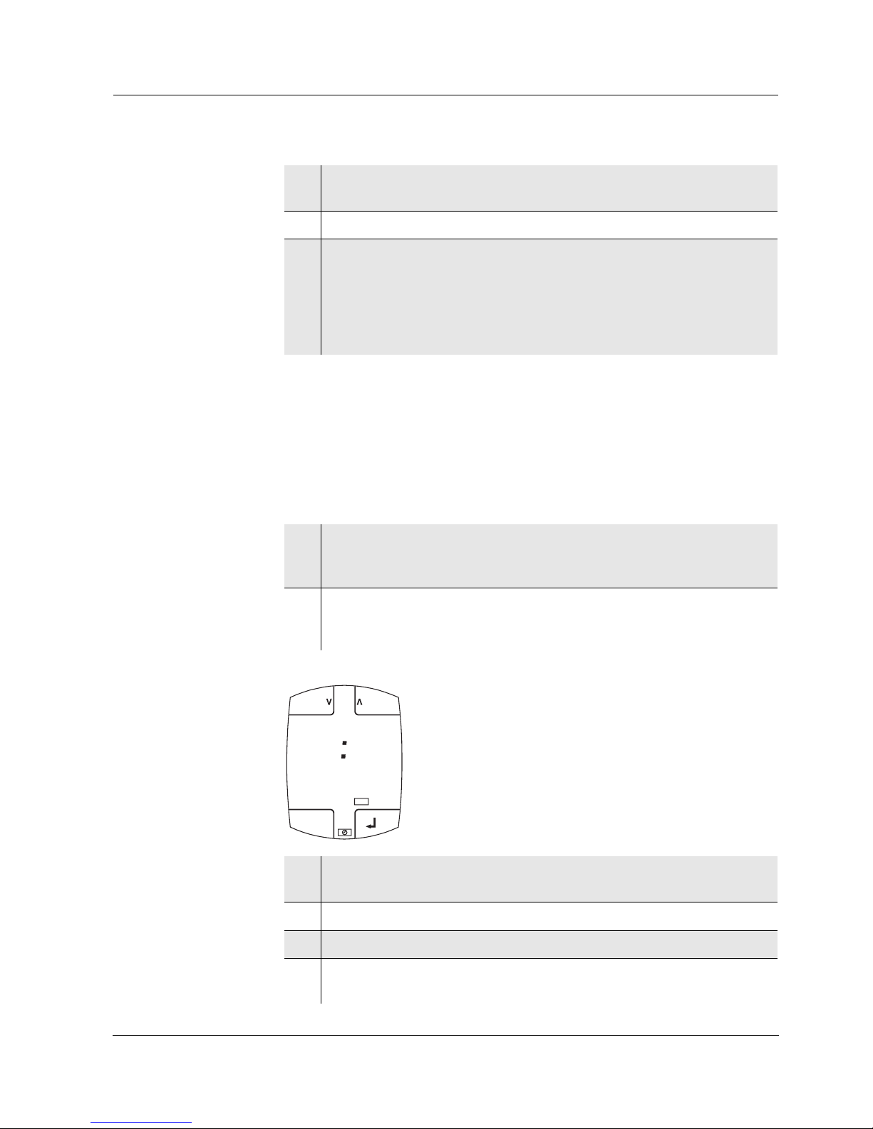
3 Display the current time as an intermediate time with <L>.
The intermediate time is displayed under the running stopwatch.
4 Stop the stopwatch with <g>.
5 Let it continue with <g>.
or
Reset the stopwatch to 00:00 with <R>.
or
Terminate the stopwatch and switch to the measuring mode display
with <E>.
1 Display the stopwatch with <U_>.
The v status indicator appears.
The stopwatch is on 00:00.
2 Select the minutes or seconds with <5_> or <6_> [<Minutes> or
<Seconds>].
The selected display flashes.
3 Set the timer interval (minutes:seconds) with <>> and <<>.
The stopwatch has been converted to a timer.
4 Confirm the setting with <g>.
5 Start the timer with <g>.
6 If necessary, display the remaining time as an intermediate time with
<L>.
nLF
Tref25
MEM
CAL
RCL
Sal
1
cm
K
C
2 5 8
S/cm
TDS
CellTC
S
SAL
O
2
TC
RESET
Cell
LAP
m
mbar
mg/l
CAL
STO
LoBat
Day.Month
h:min
Ident
Lap
8
CLR
Lin
Tref20Tref20
M
cm
k
cm
ESC
0 5 0 9
min:s
Page 40
Operation BYK LC 4
40
Note
If the timer has been stopped you can
! Reset the timer to the adjusted timer interval with <R>.
! Terminate the timer and switch to the measured value display with
<E>.
4.11 Switch-off interval
The automatic switch-off function switches off the meter automatically if no
entry is made for a specified time (switch-off interval). This saves the battery
of the meter.
You can specify the switch-off interval yourself. The switch-off interval is from
10 minutes minimum to 24 hours maximum.
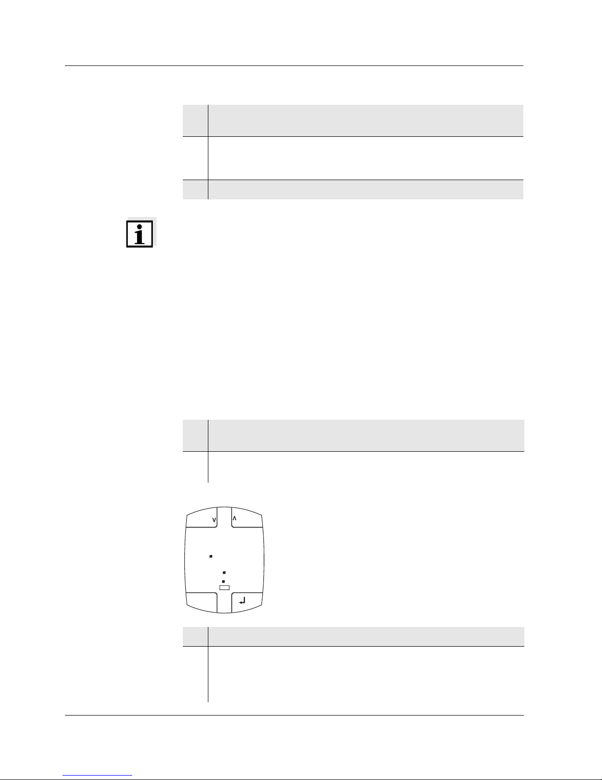
7 If necessary, stop the timer before the time has expired with <g>
and make it continue with <g>.
8 As soon as the time has expired the alarm signal sounds.
Switch off the alarm signal with <(>. The timer goes on counting
with a negative sign.
9 Stop the timer with <g>.
1 Switch on the meter with <(>.
The display test is displayed.
2 During the display test (approx. 2 sec.):
Display the switch-off interval with <M>.
3 Select a switch-off interval with <>> and <<>.
4 Confirm the setting with <g>.
The display switches to the measured value display.
The automatic switch-off function switches off the meter if no entry is
made during the switch-off interval.
min:s
CLR
d
Day.Month
MEM
CAL
C
pH
LoBat
Ident
Lap
mV
RESET
LAP
ESC
O f F
00
0 4
t
h:min
Page 41
BYKLC4 Operation
41
4.12 Reset
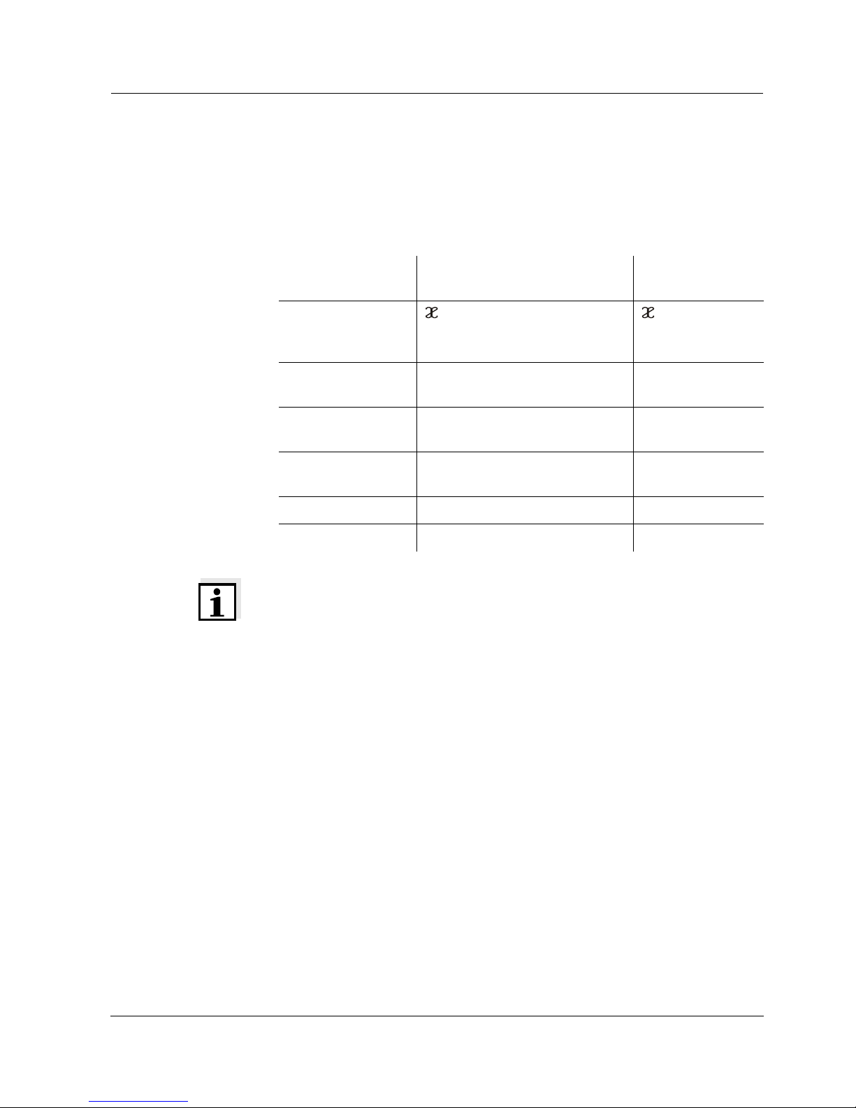
The following parameters are stored in the sensor module. The reset function
resets them to the delivery condition.
Note
The calibration data is lost when the measuring parameters are reset. Recalibrate after performing a reset. Stored data are retained.
Parameter
Sensor module, TetraCon V
Adjustable values Delivery
condition
Measuring mode , Spec. resistance, Sal, TDS ,
with adjusted cell
constant
Cell constant, to be
calibrated
0.450 ... 0.500 0.475
Cell constant, to be
adjusted
0.450 ... 0.500 0.475
Temperature
compensation
nLF, Lin, Off nLF
linear TC 0.001 ... 3.000 %/K 2.000 %/K
Tref 20 °C, 25 °C 25 °C
Page 42
Operation BYK LC 4
42
Resetting the
measuring param-
eters
Setting the
calibration interval
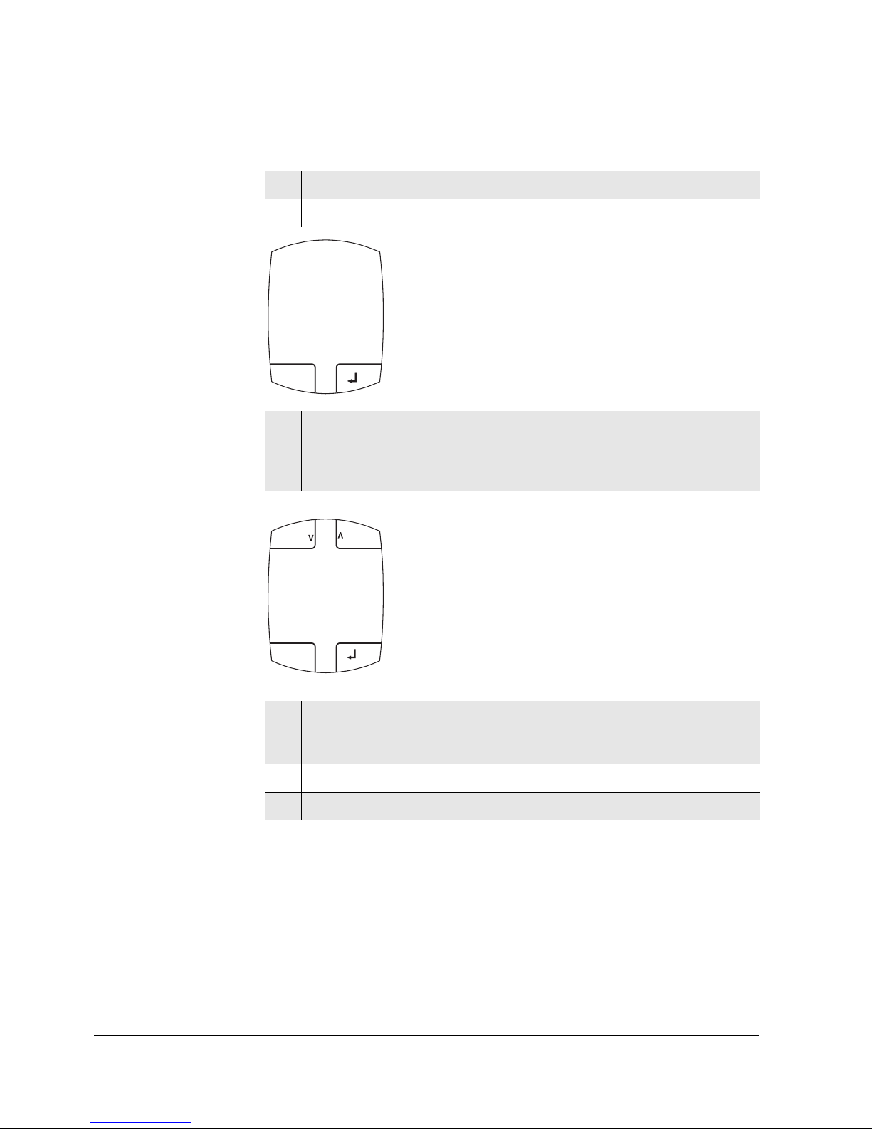
1 Start the INIT initialization menu with <C_>.
2 For initialization, select YES with <ß>.
3 Confirm with <g>.
The reset is performed. The measuring instrument switches to the
setting of the calibration interval (see section 4.8).
The display flashes.
STO
RCL
C
S/cm
Tref25
nLF
MEM
CAL
TDS
CellTC
S
SAL
O
2
TC
RESET
Cell
LAP
m
mbar
mg/l
CAL
LoBat
Day.Month
h:min min:s
Ident
Lap
8
CLR
Lin
Tref20Tref20
M
cm
k
cm
Sal
1
cm
K
ESC
1 n i t
Y E S
4 Terminate the setting with <E>.
or
Set the calibration interval in days (d) with <<> and <>>.
5 Confirm the setting with <g>.
6 Switch to the measuring mode with <g>.
Day.Month
MEM
CAL
d
C
pH
8
LoBat
min:s
Ident
Lap
mV
h:min
CLR
RESET
LAP
ESC
ESC
I n t
08d
1
Page 43
BYK LC 4 Maintenance, cleaning, disposal
43
5 Maintenance, cleaning, disposal
5.1 Maintenance
The meter is almost maintenance-free.
The only maintenance activity is exchanging the battery when it is depleted
(LoBat display indicator).
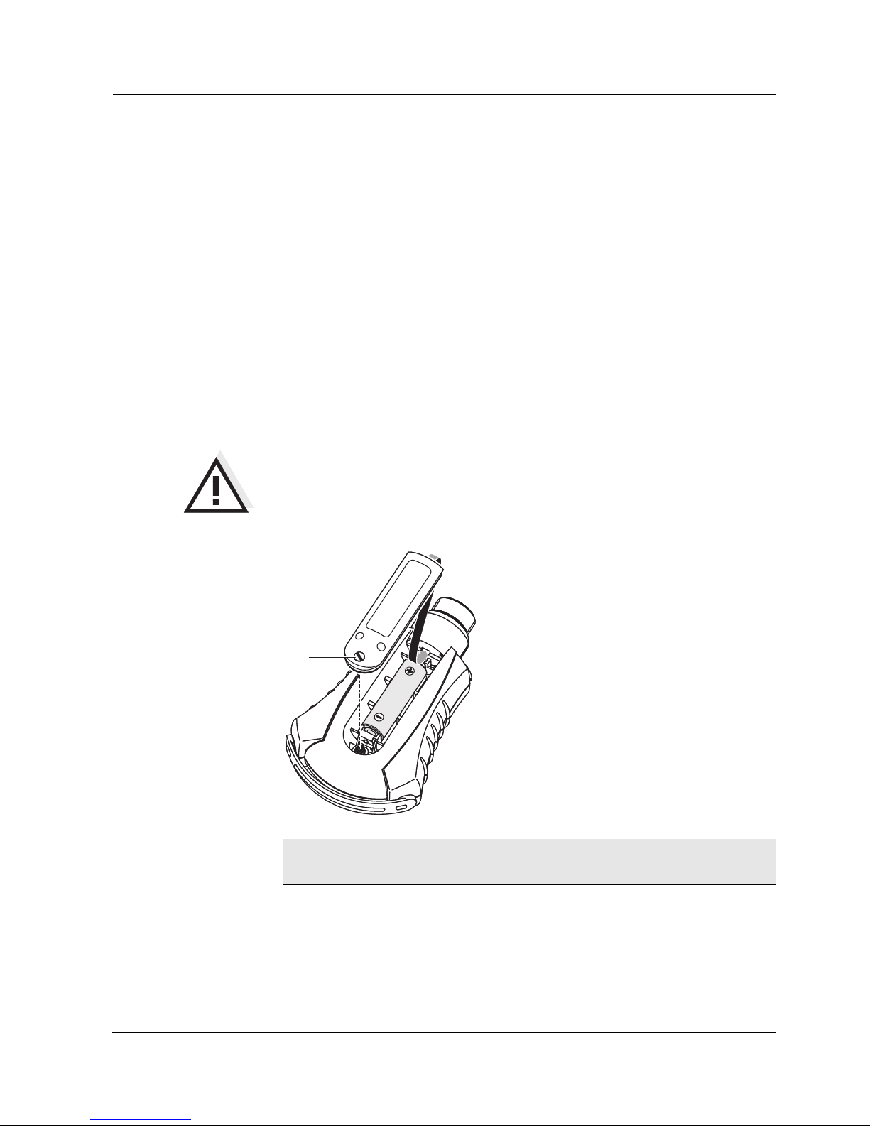
5.2 Battery exchange
The LoBat display indicator indicates that the battery should be changed.
The battery is then largely depleted.
Stored calibration data and measuring data are retained when the battery is
exchanged.
Caution
Only use leakproof alkaline manganese batteries.
Replacing the
battery
1 Unscrew the screw (1) on the back of the meter and remove the lid
of the battery compartment by pulling at the screw.
2 Remove the depleted battery from the battery compartment.
1
Page 44
Maintenance, cleaning, disposal BYK LC 4
44
5.3 Cleaning
Occasionally wipe the outside of the meter with a damp, soft cloth.
Caution
The housing components are made out of synthetic materials (polyurethane, ABS and PMMA). Thus, avoid contact with acetone and similar
detergents that contain solvents. Remove any splashes immediately.
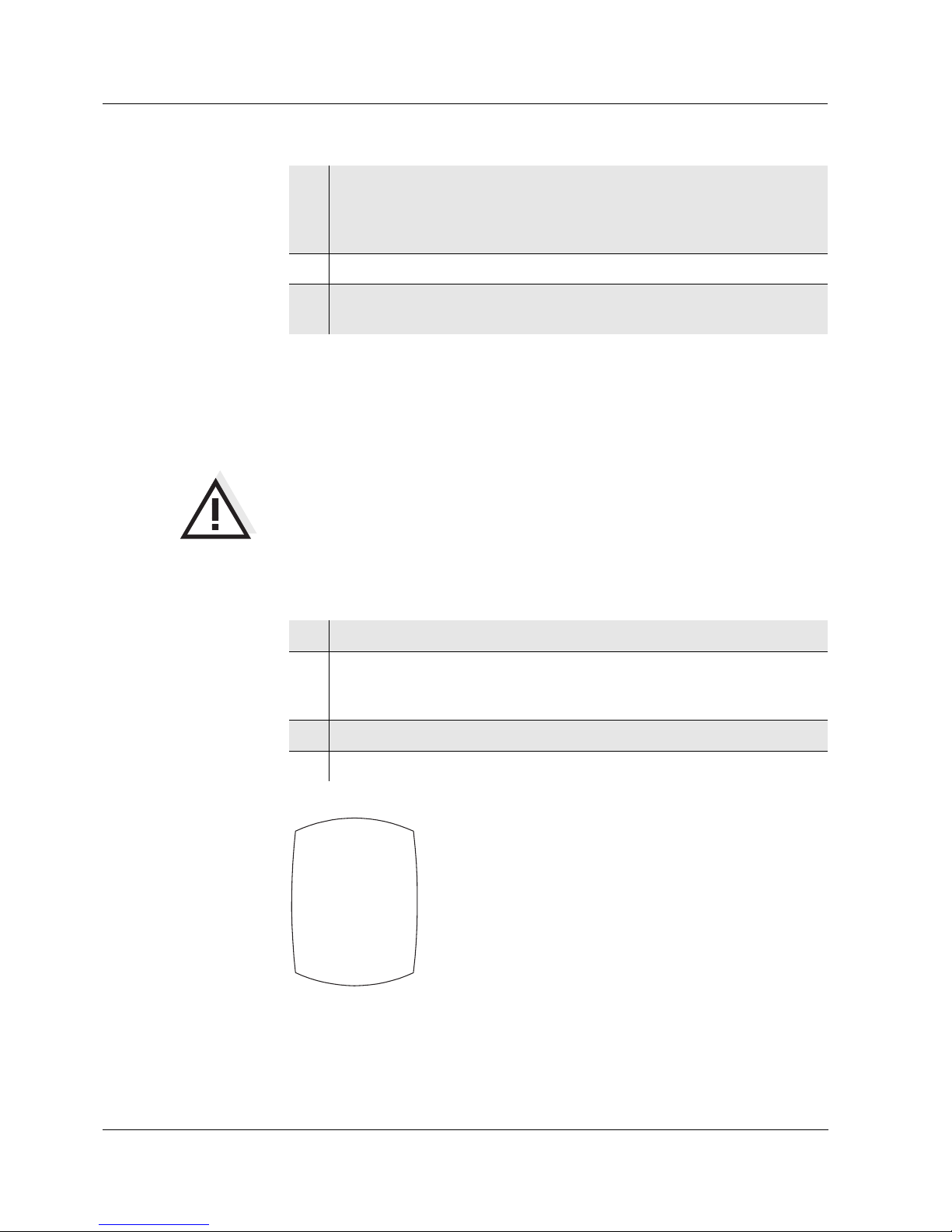
Cleaning the
touch screen
Activate the cleaning mode so the instrument will not interpret the contact
with the touch screen as entries.
3 Place the new battery (type Mignon AA) in the battery compartment.
Make sure that the poles of the battery are the right way round. The
± signs on the battery must correspond to the ± signs in the battery
compartment.
4 Close the battery compartment.
5 After the battery exchange the meter switches itself on automatically.
The display to set the time is displayed (see also section 4.10.1).
1 Switch the meter off with <E_>.
2 Switch the meter on with <(_>.
CLR PAD is displayed. The cleaning mode is active. Short touches
do not start any functions.
3 Clean the touch screen.
4 Switch to the measuring mode with <(_>.
ESC
I
0
d
Ident
CLR
Day.Month
MEM
CAL
C
pH
LoBat
min:s
Lap
mV
h:min
RESET
LAP
C I r
dap
Page 45

BYK LC 4 Maintenance, cleaning, disposal
45
Cleaning the
sensor module
We recommend to clean the sensor module thoroughly, especially before
measuring low conductivity values. Before measuring, thoroughly rinse the
sensor with deionized water.
5.4 Transport
Activate the cleaning mode. Thus, the instrument will not interpret any
contact with the touch screen as an entry while being transported, e. g. in a
pocket (see chapter 5.3).
5.5 Disposal
Dispose of the meter without the battery and the sensor module as electronic
waste at an appropriate collection point.
Contamination Cleaning agent Reaction time at
room temperature
Water-soluble substances Deionized water Any
Fats and oils Warm water and
household washing-up
liquid
Any
Heavy contamination Methylated spirits Max. 5 minutes
Lime and hydroxide coatings Acetic acid (10 %) Any
Page 46

Maintenance, cleaning, disposal BYK LC 4
46
Page 47

BYKLC4 What to do if...
47
6 What to do if...
Error message
0FL
0FL0FL
0FL, UFL
UFLUFL
UFL
Error message
Err3
Err3Err3
Err3
Error message
Err4
Err4Err4
Err4
Error message
Err5
Err5Err5
Err5
Cause Remedy
– The measured value lies outside
the measuring range
– Sensor module defective – Replace sensor module
Cause Remedy
– Erroneous calibration
– The data of the sensor module is
outside the specified characteristics.
– Recalibrate
– Reset to default setting (see
section 4.12)
– Sensor module contaminated – Clean and replace sensor
module if necessary
– Moisture in the plug connection – Dry plug and socket
– Calibration solution not suitable – Check calibration solution
Cause Remedy
No sensor module – Connect sensor module
– Check the plug connection
– Switch the meter off and then on
again.
– Perform a processor reset (see
section 6.1)
– Replace sensor module
Cause Remedy
Sensor module defective
or
Wrong sensor module
– Check the plug connection
– Switch the meter off and then on
again.
– Perform a processor reset (see
section 6.1)
– Replace sensor module
Page 48

What to do if... BYK LC 4
48
No stable
measured value
Indication, l
Meter does not
react to keystroke
Sensor symbol
flashes
Message, StoFull
StoFullStoFull
StoFull
6.1 Processor reset:
The processor reset is a simple action that can be helpful in the case of error
messages or error modes.
Cause Remedy
– Sensor module contaminated – Clean sensor module
– Temperature not stable – Adjust temperature if necessary
– Conductivity too low – Use suitable sensor module
– Organic liquids – Use suitable measuring system
Cause Remedy
– Battery almost empty – Exchange the battery (see
section 5.2)
Cause Remedy
– Operating condition undefined or
EMC load unallowed
– Perform a processor reset (see
section 6.1)
Cause Remedy
– Calibration interval expired – Recalibrate the measuring
system
Cause Remedy
– All memory locations are full – Clear the memory (see section
4.9.3)
1 Press <1> and <8> at the same time and release them again.
Stored data and calibration values are retained.
Page 49

BYKLC4 Technical data
49
7 Technical data
7.1 Measuring instrument
Dimensions approx. 140 x 80 x 33 mm (without sensor module)
Weight approx. 115 g (without sensor module, without battery)
Mechanical
structure
Type of protection IP 65 (hose-proof)
Electrical safety Protective class III
Test certificates CE
Ambient
conditions
Storage - 25 °C ... + 65 °C
Operation -10 °C ... + 55 °C
Climatic class 2
Power
supply
Battery 1 x 1.5 V, type Mignon/AA
Battery life time Maximum approx. 500 operating hours
Guidelines
and norms used
EMC EC guideline 89/336/EEC
EN 61326-A1:1998
Instrument safety EC guideline 73/23/EEC
EN 61010-1 A2:1995
Climatic class VDI/VDE 3540
IP protection EN 60529:1991
FCC Class A Equipment Statement
Note: This equipment has been tested and found to comply with the
limits for a Class A digital device, pursuant to Part 15 of the FCC Rules.
These limits are designed to provide reasonable protection against
harmful interference when the equipment is operated in a commercial
environment. This equipment generates, uses, and can radiate radio
frequency energy and, if not installed and used in accordance with the
instruction manual, may cause harmful interference to radio
communications. Operation of this equipment in a residential area is
likely to cause harmful interference in which case the user will be
required to correct the interference at his own expense.
Page 50
Technical data BYK LC 4
50
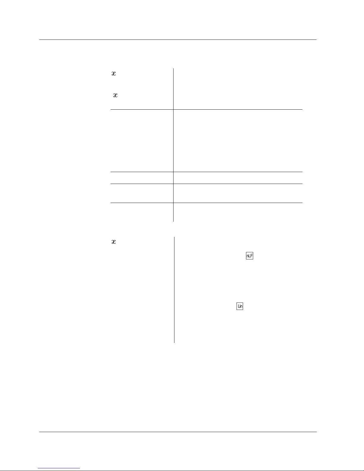
Measuring ranges
and
resolution
Accuracy
(± 1 digit)
[µS/cm]
[mS/cm]
0.0 ... 199.9
0 ... 1999
0.00 ... 19.99
0.0 ... 199.9
Spec. resistance
[kΩ*cm]
Spec. resistance
[MΩ*cm]
0.000 ... 1.999
0.00 ... 19.99
0.0 ... 199.9
0 ... 1999
0.00 ... 19.99
0.0 ... 199.9
0 ... 1999
SAL 0.0 ... 70.0 according to the IOT table
TDS [mg/l] 0 ... 1999
Factor can be set between 0.40 ... 1.00
T [°C]
T [°F]
− 5.0 ... + 105.0
23.0 ... + 212.0
,
Specific resistance
No compensation:
Accuracy ± 0.5 %
Nonlinear compensation :
Accuracy Temperature of test sample
± 0.5 % 0 °C ... 35 °C
acc. to ISO 7888, EN 27888
(*)
± 0,5 % 35 °C ... 50 °C
enhanced nLF function
Linear compensation
Accuracy Temperature of test sample
± 0.5 % 10 °C ... 75 °C
(The accuracy percentage always refers to the
measured value.)
(*) Corresponds to DEV C8
Page 51

BYKLC4 Technical data
51
Accuracy
(± 1 digit)
Cell constant,
calibrated
Cell constant,
adjusted
Reference
temperature
Memory locations 50
SAL Range 0.0 ... 42.0
Accuracy Temperature of test sample
± 0.1 5 °C ... 25 °C
± 0.2 25 °C ... 30 °C
TDS [mg/l] 1
T [°C]
T [°F]
± 0.1
± 0.54
C [cm-1] 0.450 ... 0.500
C [cm-1] 0.090 ... 0.110
0.450 ... 0.500
Tref Can be set to 20 °C or 25 °C
Page 52
Technical data BYK LC 4
52
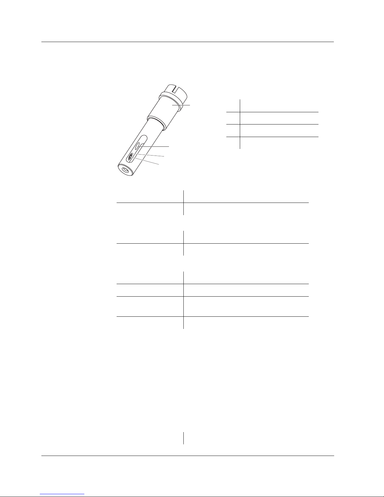
7.2 Sensor module TetraCon V
Electrodes
Material
Dimensions
Depth of
immersion
min.: 36 mm
max.: 75.5 mm (T < 50 °C)
max.: 54.0 mm (50 °C < T < 100 °C)
Connection
technique
Cell constant 0.475 cm
-1
± 1.5 %
Application range 1 µS/cm .. 200 mS/cm
Temperature
measurement
1
2
3
4
1 Plug head connector
2 Temperature sensor
3 Current electrode (ring)
4 Voltage electrode
Number of electrodes 4
Electrode material Graphite
Shaft Epoxy, black
Connection head PVC
Shaft diameter 15.3 mm
Shaft length 54 mm
Diameter of plug head
connector
19 mm
Total length of sensor 91.5 mm
Vario plug head connector with integrated data storage
Thermistor type Integrated NTC (30 kΩ / 25 °C)
Page 53

BYKLC4 Technical data
53
Storage medium Air
Accessories
Material of thermistor
enclosure
Graphite
Working temperature -5 .. +100°C
Thermistor response
behavior
t
99
< 20 sec.
Sensor accuracy ± 0.2 K
Designation Order number
E/SET Calibration set 300 572
Page 54

Technical data BYK LC 4
54
Page 55

BYKLC4 Lists
55
8Lists
This chapter provides additional information and orientation aids.
Abbreviations The list of abbreviations explains the indicators and the abbreviations that
appear on the display and in the manual.
Specialist terms The glossary briefly explains the meaning of the specialist terms. However,
terms that should already be familiar to the target group are not described
here.
Index The index will help you to find the topics that you are looking for.
Page 56
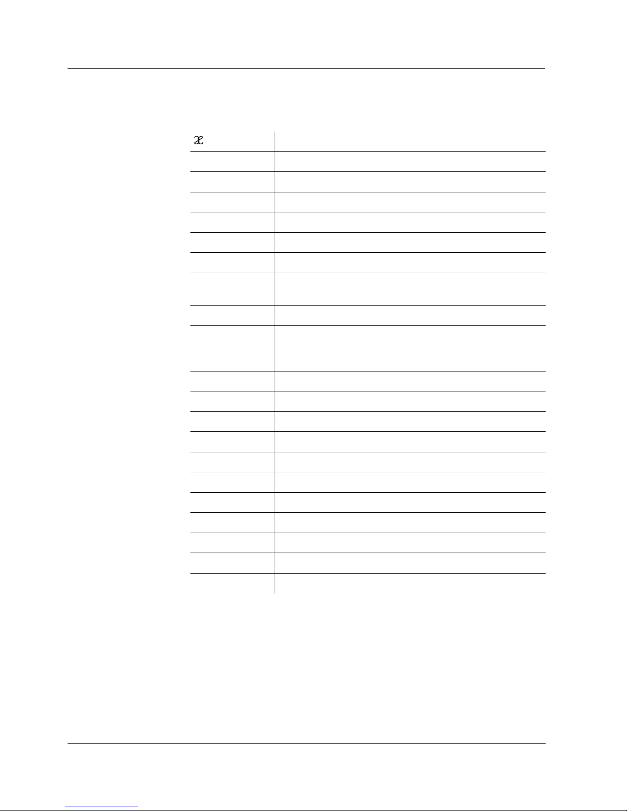
Lists BYK LC 4
56
Abbreviations
Conductivity value
°C Temperature unit, Celsius
°F Temperature unit, Fahrenheit
AR AutoRead (drift control)
C Cell constant cm
-1
Cal Calibration
CELL Cell constant
E3 Error message
see
CHAPTER 6 WHAT TO DO IF...
Ident ID number
Init Initialization
Resets individual basic functions to the status they had
on delivery
Int Interval
Lin Linear temperature compensation
LoBat Batteries almost empty (Low Battery)
nLF Nonlinear temperature compensation
OFL Display range exceeded (Overflow)
SAL Salinity
TC Temperature coefficient
TDS Total dissolved solids
Tref 20/T20 Reference temperature 20 °C
Tref 25/T25 Reference temperature 25 °C
UFL Value is below the display range (Underflow)
Page 57

BYKLC4 Lists
57
Glossary
Adjusting To manipulate a measuring system so that the relevant value (e. g. the
displayed value) differs as little as possible from the correct value or a value
that is regarded as correct, or that the difference remains within the
tolerance.
AutoRead Name for a function to check the stability of the measured value.
Calibrating Comparing the value from a measuring system (e. g. the displayed value)
to the correct value or a value that is regarded as correct. Often, this
expression is also used when the measuring system is adjusted at the same
time (see adjusting).
Calibration The cell constant is determined through calibration. To do so, the
conductivity measuring cell is immersed into a series of aqueous salt
solutions with an exactly known electric conductivity. The relevant
conductivity values are determined using the conductivity meter.
Cell constant Linear factor describing the geometrical dimensions of a measuring cell and
its electrodes.
! With the value of the cell constant you can roughly describe the
application range of a sensor module.
! The cell constant is determined through calibration in one or several
calibration solutions.
Conductivity The conductivity value is a sum parameter for the ion concentration of a test
sample.
Control standard
solution
Solution with a known conductivity to determine or check the conductivity.
Drift control See A
UTOREAD.
Measured
parameter
The measured parameter is the physical dimension determined by
measuring, e. g. pH, conductivity or D. O. concentration.
Measured value The measured value is the special value of a measured parameter to be
determined. It is given as a combination of the numerical value and unit
(e. g. 3 m; 0.5 s; 5.2 A; 373.15 K).
Measuring medium The substance to be measured. It can be liquid or solid.
Measuring solution /
test sample
Designation of the sample ready to be measured. Normally, a test sample
is made by processing the original sample. The test sample and original
sample are identical if the test sample was not processed.
Measuring system The measuring system comprises all the devices used for measuring, e. g.
meter and sensor. In addition, there is the cable and possibly an amplifier,
terminal strip and armature.
Page 58

Lists BYK LC 4
58
Reference
temperature
In order to compare values measured at different temperatures, the values
have to be converted to a fixed temperature. This temperature is 25 °C, or,
as an exception, 20 °C.
Reset Restoring the original condition of all settings of a measuring system.
Resistance All substances (solids, liquids, or gases) with mobile charge carriers, like for
example electrons or ions, have a finite ohmic resistance, which means they
have an electric conductance or an electric conductivity that can be
measured.
Resolution Smallest difference between two measured values that can be displayed by
a meter.
Salinity The salinity is a sum parameter especially for seawater.
It quotes the salt content.
Standard solution The standard solution is a solution where the measured value is known by
definition. It is used to calibrate a measuring system.
Temperature
compensation (TC)
The temperature has a very strong impact on the electrical conductivity. To
be able to compare measured values, it is necessary to temper or convert
the test sample to a reference temperature.
Total dissolved
solids (TDS)
Mass that remains of the substances dissolved in an aqueous solution after
a fixed filtering and drying procedure, as far as these substances are not
volatile under the conditions of this procedure. The total dissolved solids
refer to the volume of the filtered aqueous sample used and are given in
mg/l.
Page 59

BYKLC4 Index
59
9 Index
A
Alarm function .........................................37
Authorized use ...........................................7
C
Calibration interval ...................................31
Cell constant
adjust manually
..................................22
determine ..........................................24
Clock ......................................................35
Conductivity .............................................18
D
Data record .............................................32
Date and time ..........................................35
Delivery condition ....................................41
Displaying calibration data ........................30
E
Energy saving feature ..............................16
I
Initial commissioning ..................................9
L
Linear temperature coefficient ...................28
Linear temperature compensation .............26
LoBat ......................................................48
M
Measuring ...............................................17
conductivity, specific resistance, salinity,
TDS
...............................................18
temperature .......................................17
N
Nonlinear temperature compensation ........26
O
Operating safety ........................................8
R
Reference temperature .............................17
Reset ..................................................... 41
S
Safety ...................................................... 7
Safety precautions .................................... 7
Salinity ................................................... 18
Saving .................................................... 32
Saving measuring data ............................ 32
Scope of delivery ...................................... 9
Specific resistance .................................. 18
Stopwatch .............................................. 38
Switch-off interval .................................... 40
T
TDS ....................................................... 18
Temperature compensation
linear
.......................................... 17, 26
nonlinear ..................................... 17, 26
off ............................................... 17, 26
Temperature measurement ...................... 20
Temperature unit ..................................... 20
Timer ..................................................... 39
Touch screen .......................................... 13
Page 60

Index BYK LC 4
60
Page 61

BYK-Gardner GmbH
Lausitzer Str. 8
D-82538 Geretsried
Germany
Tel: +49-8171-3493-0
Fax: +49-8171-3493-140
E-Mail: [email protected]
Internet: http://www.byk-gardner.com
 Loading...