

Page 1
1
■ Professional & High-quality
■ Diligent & Focus
■ Passionate & Sincere
■ Active & Care
Superb skills & honest hearts
BYD
Superior and Sincere Services
BYD sincere service brand was established in 2006, adhering to the service concept
of “Superb Skills & Honest Hearts” from all BYD after-sales staff.
In the article “A Famous Doctor with Superbe Skills & Honest Hearts”, Sun Simiao, a
famous doctor in Tang Dynasty, discussed two issues concerning medical ethics:
the first is “Superb”, that is, a doctor should have superb medical skills and must
learn medical knowledge extraordinary and diligently. The second is “Sincere”, that
is, a doctor should have a noble moral, and a sincere heart to regard one`s distress
as his. BYD after-sales staff have introduced the concept of “Superb Skills & Honest
Hearts” from Sun Simiao into the automobile after-sales field and defined
“Professional & Sincere” as BYD sincere service brand with the brand features as
below:
BYD sincere service firmly believes that the exquisite service technologies come
from professional, diligent, and sincere service attitudes, responsibilities and
intentions. We are always committed to providing a high level of after-sales services
for BYD Auto users and their cars.
Page 2
2
Foreword
Tip
It refers to any item that must be followed for ease maintenance.
Note
It refers to any item to prevent any injury or damage.
Warning
It refers to any item to prevent any injury.
Welcome to use BYD passenger car; please read the manual carefully to help you normally
use and maintain your car.
Special note: It is strongly recommended to choose genuine spare parts and use, maintain
and repair your car in accordance with the requirements in the manual. For any car that is
replaced and modified with non-original spare parts, its performance may be affected,
especially for safety and durability; and the resulted damage and performance problems
will be beyond the warranty. In addition, any modification for your car may not be consistent
with national laws and regulations and local government regulations.
Thank you for choosing BYD passenger car; welcome your comments and suggestions. In
order to ensure better services for you, please be sure to provide your accurate contact
information. If there is any change, please contact BYD Auto Authorized Service Station to
update it in the system. At the same time, please pay attention to relevant national laws
and regulations and local policies and regulations, and register your car as soon as
possible; otherwise, there may be a risk of register rejection.
In the manual, the positions marked with “Tips”, “Notes” and “Warnings” must be followed
carefully, to avoid any injury or damage. The representations and usages of various
reminding information types are as follows:
Page 3
3
The safety mark shown on the left indicates “Not Do It” or “Not Allow Its
Occurrence”.
The manual is used to help you use the product correctly and does not
represent any description of the configuration and software version of
the product. For product configurations and software versions, please
consult the contract associated with the product (if any) or consult your
vendor.
To inquire for the power battery recycling network, please access the
official website of BYD Auto:
https://www.byd.com/cn/socialresponsibility/batteryrecycle.html
For detailed product usage instructions, please follow “BYD Fans Club”
on WeChat, or scan the following small program QR code.
201906 version
BYD Auto Industry Co., Ltd. All rights reserved
Any part or all of the manual cannot be reproduced or copied
without the written permission of BYD Auto Industry Co., Ltd.
All copyrights are reserved
Page 4

4
Overview of BYD S1 EV passenger car
BYD S1 EV car is a new energy, new power and pure electric passenger
vehicle, and is an environmentally friendly product strived by BYD. The
body is a load-bearing type, the stringer is front-and-back through type,
and the power battery pack is integrated with the body to fully guarantee
the safety of the battery pack and the car.
Since BYD S1 EV car is driven by a motor under various operating
conditions, it has completely achieved zero emissions in terms of
environmental protection.
The car is completely driven under pure electric power conditions, so the
noise inside and outside the car is extremely small, which can provide
users with driving and riding experiences that the fuel-driven car cannot
achieve.
The safety of the high-voltage system is fully considered in the design
process of the car, and the safety of the passengers in the car can be
fully protected in case of any collision.
The battery management unit can be used to monitor the power battery
at all times, and adjust the power output from each battery unit based on
various performance indexes, such as voltage and current, to prevents a
series of faults affecting battery performance, such as overcharge,
overdischarge, and overtemperature, and so as to ensure the battery
operation under normal conditions.
The 120kW motor or 70kW motor can provide high speed and high
torque for S1 EV to realize powerful startup and acceleration
performance.
Page 5

5
Picture Index
Search by illustration
1
Safety
Make sure to read this section carefully
2
Dashboard
How to read various meters, warning lights, indicators, and etc.
3
Controller
operation
Opening and closing of doors and windows adjustment before driving,
and etc.
4
Use and drive
Necessary driving operations and suggestions
5
Interior devices
Use of interior devices, etc.
6
Maintenance
Car maintenance steps
7
In case of a fault
Countermeasures in case of a fault or emergency
8
Vehicle
specifications
Vehicle specifications, customized functions, etc.
Index
Alphabet index
Page 6

6
Contents
1
Safety
2
Dashboard
3
Controller Operations
4
Use and drive
Superior and Sincere Services ................. 1
Foreword ..................................................... 2
Overview of BYD S1 EV passenger car ... 4
1-1 Seatbelt .............................................. 18
Introduction to the seatbelt ................. 18
Use of seatbelt .................................... 20
1-2 Airbag system ................................... 23
Introduction to the airbag system ....... 23
Driver and front passenger airbags .... 24
Front passenger seat side airbag (if
fitted) ................................................... 27
Side curtain airbag (if fitted) ................ 28
Airbag triggering conditions and notes
............................................................ 29
1-3 Child restraint device ........................ 35
Child restraint device .......................... 35
Installation of child restraint device ..... 36
1-4 Anti-theft system ............................... 40
Anti-theft system ................................. 40
Key ...................................................... 54
Lock/unlock the door ........................... 57
Smart access and start system ........... 61
Child lock ............................................. 65
3-2 Seat..................................................... 66
Front seat adjustment ......................... 66
Rear seat folding ................................. 68
Headrest .............................................. 69
3-3 Steering wheel ................................... 70
Steering wheel adjustment .................. 70
3-4 Switch................................................. 71
Light switch ......................................... 71
Wiper switch ........................................ 77
Front left door switch assembly .......... 81
Passenger window control switch ....... 84
Emergency warning indicator switch ... 85
Lighting adjustment switch group ........ 85
Mode switch group .............................. 86
Steering wheel switch group ............... 87
Sunroof switch (if fitted)....................... 95
B-call/E-call switch(if fitted) ................. 97
Indoor light switch ............................... 98
2-1 Dashboard ......................................... 42
Dashboard view .................................. 42
Indicator/ warning indicator ................. 43
3-1 Key and door ..................................... 54
4-1 Charge device.................................. 103
Charge instructions ........................... 103
Charge method ................................. 107
Smart charge function ....................... 112
Charging port electric lock control
function .............................................. 112
Page 7

Contents
7
5
Interior devices
4-2 Battery ............................................. 116
Power battery.................................... 116
Battery .............................................. 119
4-3 Use essentials ................................. 121
Running-in period ............................. 121
Trailer towing .................................... 121
How to save the power and extend
the service life of your car ................. 122
Carry the luggage ............................. 124
Fire prevention .................................. 125
4-4 Start and drive ................................ 127
Start .................................................. 127
Remote start function ....................... 130
Gear actuator .................................... 131
Electronic parking ............................. 132
Driving essentials.............................. 136
4-5 Use of driver assistance functions
.......................................................... 139
Cruise control (if fitted)...................... 139
Panoramic image system (if fitted) ... 142
Parking image system (if fitted) ........ 144
Parking assist system (if fitted) ......... 148
Driving safety system........................ 153
Low speed sound system (AVAS) (if
fitted) ................................................. 157
Tire pressure monitoring ................... 159
4-6 Other main function descriptions
.......................................................... 163
Exterior rearview mirror defroster ..... 163
Interior rearview mirror (if fitted) ....... 165
Wiper ................................................ 166
Snow chain ....................................... 168
5-1 Multimedia and radio ...................... 170
Multimedia operation panel ............... 170
Radio operation panel ....................... 172
5-2 Air conditioning............................... 173
A/C panel (if fitted) ............................ 173
A/C operation panel (if fitted) ............ 174
A/C operation panel and interface (if
fitted) ................................................. 175
Function definition ............................. 176
Air vent .............................................. 180
Purifying system (if fitted) .................. 181
5-3 Storage device ................................ 184
Right storage box .............................. 184
Mobile phone slot .............................. 184
Cup holder ......................................... 184
Central storage box ........................... 185
Card slot ............................................ 185
Front central armrest storage box ..... 185
Rear storage box............................... 186
5-4 Other interior device ....................... 187
Sunvisor ............................................ 187
Safety handle .................................... 188
Front row USB/charging port ............ 188
Rear charging port (if fitted) .............. 189
12V standby power supply ................ 189
Page 8

8
Contents
6
Maintenance
7
In case of a fault
8
Vehicle specifications
Tire deflation ..................................... 229
Use the spare wheel ......................... 231
6-1 Maintenance instructions .............. 192
Maintenance cycle and content ........ 192
6-2 Regular maintenance ..................... 198
Regular maintenance........................ 198
Car corrosion protection ................... 198
Painted surface maintenance tips .... 199
Clean the car .................................... 200
Clean the inside of the car ................ 202
6-3 Auto-mantenimiento ....................... 205
Notes about self-maintenance .......... 205
Front hatch ........................................ 208
Cooling system ................................. 209
Scrubber ........................................... 210
Braking system ................................. 211
Wiper blade ....................................... 211
Air conditioning system ..................... 213
Tire .................................................... 214
Fuse .................................................. 217
7-1 In case of a fault.............................. 226
Emergency shutdown system ........... 226
Car fire rescue .................................. 227
Rescue in event of a vehicle impact
.......................................................... 227
If the car needs to be towed .............. 238
8-1 Data information.............................. 242
Vehicle parameters ........................... 242
8-2 Tips ................................................... 245
Vehicle identification number ............ 245
Warning label .................................... 248
Microwave windoww ......................... 249
Page 9
Picture Index
9
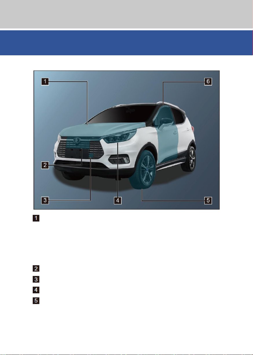
■ Outside
Front hatch .............................................................................................................. P208
Cooling system ....................................................................................................... P209
Scrubber ................................................................................................................. P210
Braking system ....................................................................................................... P211
Front cabin fuse box ............................................................................................. P217
Charging port cap ..................................................................................................... P99
Traction holes ......................................................................................................... P238
Combination lights .................................................................................................... P71
Tires ........................................................................................................................ P214
Snow chains ........................................................................................................... P168
In case of a tire deflation ........................................................................................ P229
Page 10

10
Picture Index
Doors ........................................................................................................................ P57
Locking/unlocking operation ..................................................................................... P57
Page 11
Picture Index
11
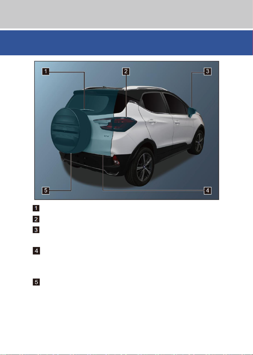
Rear wiper .............................................................................................................. P166
Combination lights .................................................................................................... P71
Electric rearview mirrors ......................................................................................... P163
Lens adjustment ..................................................................................................... P163
Back door .................................................................................................................. P58
Carrying luggage .................................................................................................... P124
Attached tools ......................................................................................................... P229
Replacement of the spare wheel ............................................................................ P233
Page 12
12
Picture Index
■ Dashboard
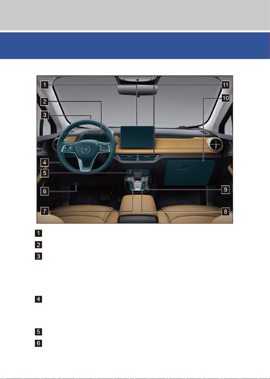
Steering wheel adjustment ....................................................................................... P70
Steering wheel switch assembly ............................................................................... P83
Cruise control (if fitted) .......................................................................................... P139
Headlight adjustment switch ..................................................................................... P85
Mileage adjustment switch ....................................................................................... P85
Multimedia display screen ...................................................................................... P170
Combination instrument ............................................................................................ P42
Steering wheel .......................................................................................................... P70
Lighting adjustment switch group ............................................................................. P85
Central control storage box .................................................................................... P185
Front hatch opening handle .................................................................................... P208
Page 13

Picture Index
13
Mode switch group.................................................................................................... P86
Economy mode button .............................................................................................. P86
Sport mode button .................................................................................................... P86
Snow mode button .................................................................................................... P86
A/C panel buttons ................................................................................................... P173
Volume knob/Audio OFF/Reboot multimedia button .............................................. P170
Right storage box.................................................................................................... P184
Air vent .................................................................................................................... P180
Central air outlet ..................................................................................................... P180
Left/right air outlets ................................................................................................. P180
Page 14
14
Picture Index
■
Inside
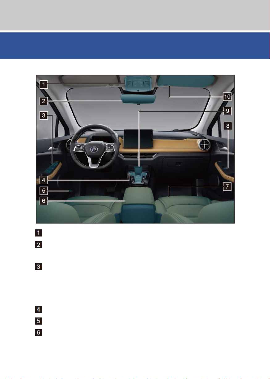
Manual anti-glare interior rearview mirror (if fitted) ............................................... P165
Central control door lock ........................................................................................... P83
Power window switch................................................................................................ P81
Exterior rearview mirror electric adjustment/folding switch ....................................... P84
Indoor light/sunroof switch (if fitted) ................................................................... P98/95
Interior rearview mirror............................................................................................ P165
Front left door switch assembly ................................................................................ P81
Emergency warning indicator switch ........................................................................ P85
Charging cap opening switch ................................................................................. P107
Front central armrest storage box .......................................................................... P185
Page 15
Picture Index
15
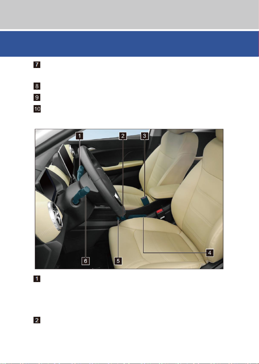
Front seats ................................................................................................................ P66
Seat adjustment ........................................................................................................ P67
Passenger window control switch ............................................................................. P84
Gear actuator .......................................................................................................... P131
Sunvisor .................................................................................................................. P187
Makeup mirror (if fitted) ......................................................................................... P187
Wiper switch ....................................................................................................... P77/79
Front and rear windshield wipers ......................................................................... P77/79
Front windshield scrubber ................................................................................... P77/79
Rear windshield wiper and scrubber ................................................................... P78/80
Mobile phone tray ................................................................................................... P184
Page 16

16
Picture Index
Seat belt buckle ........................................................................................................ P20
Cup holder .............................................................................................................. P184
Front row USB/charging port .................................................................................. P188
Light switch .......................................................................................................... P71/73
Turning on position light ...................................................................................... P71/74
Turning on the low beam ..................................................................................... P72/74
Turning on the overtaking lights .......................................................................... P72/74
Turning on the high beam .................................................................................... P72/74
Turning on the turn signal .................................................................................... P73/75
Page 17

1
Precauciones de seguridad
Safety
1
1-1 Seatbelt ............................................. 18
Introduction to the seatbelt ................. 18
Use of seatbelt.................................... 20
1-2 Airbag system ................................... 23
Introduction to the airbag system ....... 23
Driver and front passenger airbags .... 24
Front passenger seat side airbag (if
fitted) ................................................... 27
Side curtain airbag (if fitted) ............... 28
Airbag triggering conditions and notes 29
1-3 Child restraint device ........................ 35
Child restraint device .......................... 35
Installation of child restraint device .... 36
1-4 Anti-theft system ............................... 40
Anti-theft system ................................. 40
Page 18
18
1-1 Seatbelt
Introduction to the seatbelt
Note
● Before driving, ensure that all the passengers in the car have correctly fastened the
seatbelts; otherwise, the passengers in the car are more susceptible to serious
physical injuries or even death in case of emergency braking or collision.
● The seatbelts in the car is mainly designed on base of the size of the adult and are
not suitable for children; please choose the appropriate child restraint device based
on the ages and sizes of the children.
● If a seatbelt is damaged or abnormal, it is recommended to contact BYD Auto
Authorized Service Station for confirmation and disposal immediately, do not use
the corresponding seat before confirmation.
Seatbelt emergency locking (ELR) function
1-1 Seatbelt
Many studies have shown that the correct use of seatbelts can effectively reduce the
casualties of passengers in the car in case of emergency braking, sudden steering or
collision accident. Please carefully read and strictly observe the following contents.
■ Based on the special statement from BYD, the driver and passengers in the car must
wear the seatbelts in any time; otherwise, it may increase the possibility of injuries or
serious injuries in case of an accident.
■ The seatbelts provided for the car are designed especially for adults; please choose
the appropriate seatbelts based on the actual conditions.
■ Any child must sit in the rear seats and wear the seatbelt for protection. Based on
accident statistics, a child who uses a child restraint device correctly in the rear seat is
safer than one seated in the front seat.
■ Do not allow a child to stand or kneel in the rear seat. In case of an emergency braking
or collision, an unprotected child may be seriously injured or even death; likewise, do
not allow a child to sit on their laps, to avoid inadequate protection for the child in case
of an emergency braking or collision.
■ In case of a sharp turn, emergency braking or collision, when the passenger body
leans forward quickly, the seatbelt will be locked automatically to achieve effective
restraint and protection for the passenger; when the car is driven smoothly, the
seatbelt will be pulled out slowly and steady with the passenger movement, to ensure
free movement of the passenger.
■ If the seatbelt cannot be pulled out from the retractor, tighten and release the seatbelt
to smoothly pull it out from the retractor.
Page 19
1
Safety
1-1 Seatbelt
19
Seatbelt automatic locking (ALR) function (if fitted)
Tip
● When the child restraint device is fixed with the seatbelt automatic locking (ALR)
function, please confirm that the automatic locking function is activated.
● Pull out the seatbelt completely to activate the automatic locking function; at the
time, the seatbelt can only be retracted and cannot be pulled out, and a continuous
“Click” sound will be sent when the seatbelt is retracted.
Seatbelt preload limiting function (if fitted)
The seatbelt automatic locking (ALR) function can be used to secure the child restraint
device. Pull out the seatbelt completely to activate the locking function. After the locking
function is activated, the seatbelt can only be retracted and cannot be pulled out, and a
continuous “Click” sound will be sent when the seatbelt is retracted. After the seatbelt is
completely retracted, the automatic locking function will be closed automatically, and the
seatbelt can be pulled out and retracted freely. If the seatbelt cannot be pulled out from the
retractor, simply pull out the seatbelt a little and release it to smoothly pull the seatbelt out
from the retractor.
In case of a serious frontal collision and when the triggering conditions of the preloading
device are met, a part of the seatbelt can be quickly retracted and locked with the
preloading device to enhance the protection for the passenger. The preload limiting device
can limit the restraining force of the seatbelt to the passenger body to a certain extent, to
avoid damage to the passenger due to excessive restraining force.
Page 20
20
1-1 Seatbelt
Use of seatbelt
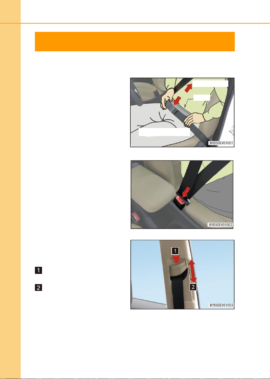
2. Adjust the three-point seatbelt
position.
■ Pull the seatbelt out smoothly, so
that it can across the shoulder near
the seatbelt pulling-out position and
the chest; the seatbelt should not
cross under the arm or the back of
the neck.
■ Keep your waist belt as low as
possible to your hip; do not buckle
the belt at the waist.
3. Insert the latch into the buckle until
a click is heard, and pull the latch in
the opposite direction to confirm
that the seatbelt is locked
successfully. Note that the seatbelt
cannot be twisted.
4. Adjust the seatbelt height adjuster
(front row) to the appropriate
position for optimum comfort and
protection.
Press the seatbelt height adjuster
to release the button.
Hold the height adjuster and move
it up and down to adjust the front
seatbelt to the appropriate height
and release the seatbelt height
adjuster.
Tighten the slack section
Too high
Keep it as low as possible to the hip
1. Adjust the seat to the proper position and adjust the backrest to the proper angle. (See
the seat adjustment method)
5. After the adjustment is completed, pull the shoulder belt firmly to confirm that the
seatbelt height adjuster is locked.
Page 21
1
Safety
1-1 Seatbelt
21
Tip
● The shoulder belt should cross the middle of the shoulder. The seatbelt should be
away from the neck and cannot easily slip off from the shoulder; otherwise, the
seatbelt will not perform its proper protection and even a serious injury may occur in
case of an emergency braking or accident.
● The waist belt should be as low as possible to across the hip to avoid any injury
when the abdomen is tightened by the seatbelt excessively.
● The seatbelt should be in close contact with the body for better protection.
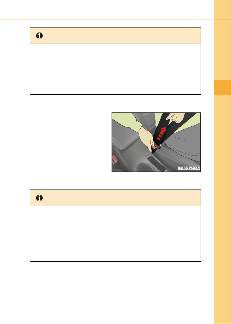
Unlocking of seatbelt
When the red unlocking button on the
buckle is pressed, the latch will be
popped out and the seatbelt will be
retracted automatically.
Tip
● When the seatbelt is unlocked, hold the latch with one hand and press the red
unlocking button on the buckle with the other hand, the seatbelt will be retracted
automatically.
● Do not insert coins, paper clips or any other foreign objects in the buckle to avoid
effect on the correct connection between the latch and the buckle.
● The seatbelt must be kept clean and dry; if it needs to be cleaned, neutral soapy
water or warm water should be used. Do not use bleach, dye or abrasive cleaner,
which may seriously impair the performance of the seatbelt.
Page 22

22
1-1 Seatbelt
Note
● At the same time, the seatbelt can only be used for one single passenger; do not
share one seatbelt for two or more passengers, even for children.
● Avoid excessive tilting of the seat backrest. When the seat backrest is upright, the
seatbelt can provide the best protection.
● Do not pinch the seatbelt, latch or buckle in the door; otherwise the seatbelt may be
damaged.
● Regularly check the seatbelt for cutting traces, wear, looseness or any other
abnormity. In any case of an abnormity, please contact BYD Auto Authorized
Service Station for confirmation and handling immediately; do not use the
appropriate seat before confirmation.
● Do not remove, disassemble or modify the seatbelt without permission.
● It is recommended to check the seatbelt at BYD Auto Authorized Service Station in
any case of an accident. If the preloading function is activated, the seatbelt must be
replaced.
● In case of a serious accident, even if there is no any obvious damage of seatbelt or
seat, they should be replaced together.
● The pregnant women should also wear the seatbelts with the correct method;
especially, the waist belt should across the hip as far as possible to be low, to avoid
serious injuries of the pregnant women and the fetus due to excessive tightening of
the waist belt in case of an accident.
Page 23
1
Safety
1-2 Airbag system
23
Introduction to the airbag system
Tip
● Please always wear the seatbelts during driving process.
● Please maintain the correct sitting attitude to maximize the protection of the seatbelt
and the airbag system.
● Do not allow a child to sit in the front passenger seat.
● Do not disassemble the airbag without permission.
● The use of the seat covers other than our genuine products may result in
performance reduce of the airbags or accidental injuries. Do not place any item
between the side airbag and the passenger.
● Do not apply an excessive force on the side of the seat with the side airbag.
1-2 Airbag system
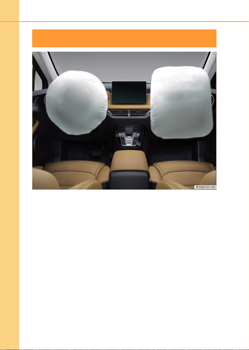
■ The airbag system is a part of the auxiliary restraint system and is used for
supplementary for the seat and the seatbelt. The airbag system can provide additional
protection for the heads and chests of the passengers and the driver in case of a
serious frontal collision, so as to reduce the casualties.
■ Based on the types of collision, the airbag system includes generally front airbag and
side airbag. The front airbag includes the driver airbag and the front passenger airbag,
and the side airbag includes the front seat side airbag and the curtain airbag.
■ The airbag system is not a substitute for the seatbelt, and it is an integral part of the
entire passive safety system in the car.
■ The airbag system should be operated together with the seatbelt to maximize the
protection of the airbag system. Therefore, in order to ensure the safety of you and
your family, please pay special attention to “Notes” and “Tips” in the section.
Page 24
24
1-2 Airbag system
Driver and front passenger airbags
If your car is equipped with the auxiliary protection device (SRS AIRBAG) of front airbags,
including the driver airbag and the front passenger airbag, when the airbag trigger
condition is met in case of a medium to severe frontal collision, the airbags will be triggered
to protect the heads and chests of the driver and the front passenger and reduce the
injuries.
Front airbag triggering process
■ In case of a moderate to severe frontal collision, the sensor can sense rapid
deceleration and send a signal to the control unit to trigger the front airbags
immediately.
■ In case of a frontal collision, the seatbelt can hold your lower body and torso to keep
you in place. The airbag is equivalent to an air cushion to stabilize and protect your
head and chest.
■ When the severity of the collision is not up to the critical value to trigger the airbag, the
seatbelt will provide the primary protection function, and the airbag will only provide a
minimal auxiliary protection.
Page 25
1
Safety
1-2 Airbag system
25
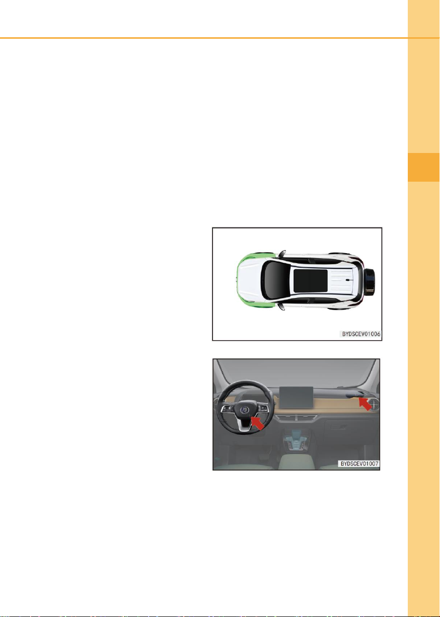
2. An accident in front of the car
(Shown green area) failed to trigger
SRS airbag.
3. The front passenger airbag cover is
scratched, cracked, or damaged.
■ The front airbag will be deflated immediately after inflation, without affecting the sight
of driver and the ability to operate the steering wheel or other control devices.
■ The airbags can be triggered quickly in several milliseconds, to provide additional
protection for the driver and the passengers in case of an accident.
■ When the airbag is triggered, it will send a loud noise but generally will not cause any
injury (but it does not exclude the possibility of damage the hearings, which will be
recovered quickly).
■ After a collision, there will be a smoke, which is the powder from the airbag surface.
Although the powder is non-toxic, a passenger with a respiratory illness may still feel
some temporary discomfort.
It is recommended to contact BYD Auto Authorized Service Station immediately in
following cases:
1. The airbag is inflated.
Page 26
26
1-2 Airbag system
Note
The following cases indicate that the airbag system is faulty:
● When the power supply is in “OK” position, the warning indicator cannot be turned
on.
● After the power supply is in “OK” position, the warning indicator cannot be turned off
after 5 seconds or cannot be turned off but turned on again.
● When the power switch is in “OFF” position, the warning indicator will be turned on.
● The warning indicator will be turned on or flash during driving process. In case of a
malfunction, it is recommended to check and repair your car as soon as possible at
BYD Auto Authorized Service Station.
4. The airbag indicator on the dashboard is turned on abnormally.
■ The airbag system is monitored by an electronic control unit and has a self-diagnostic
function, and the system status is displayed with the airbag warning indicator on the
dashboard.
● After the power supply is in “OK” position, the airbag warning indicator will be
turned on and last about 5s, and then turned off and last for more than 5s, it
indicates that the system is operated normally.
● If the airbag is turned off, the warning indicator will be always on, but it will not
have any protection function.
Page 27
1
Safety
1-2 Airbag system
27
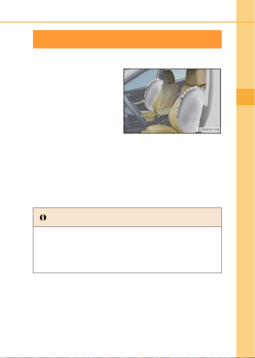
Front passenger seat side airbag (if fitted)
If your car is equipped with the driver
and front passenger side airbags (as
shown on the right figure, the airbag is
arranged on the outside of the driver
and front passenger seat backrests and
marked with “SRS SIDE AIRBAG”).
During driving, when the airbag system
ECU senses a moderate to severe side
collision and the airbag triggering
conditions are met, the airbags will be
triggered to protect the chests of the
occupant on the collision side to reduce
the injury.
Tip
● Do not allow the water to wet the seat backrest. If the backrest is wetted, it may
interfere with the normal operation of the side airbag system.
● Do not cover or replace the seat backrest cover without consulting with BYD Auto
Authorized Service Station. Any inappropriate seat backrest cover replacements or
coverings may interfere with the triggering of the seat side airbag in case of a
collision.
Seat side airbag triggering process
■ In case of a side impact, generally only the airbag on the collision side can be
triggered.
■ If the collision occurs on the front passenger side, the front passenger airbag will be
triggered even if the front passenger seat is not occupied.
■ In order to obtain the best protection from the seat side airbag, the occupant must
correctly wear the seatbelt, maintain the upright sitting attitude and be against the seat
backrest.
Page 28
28
1-2 Airbag system
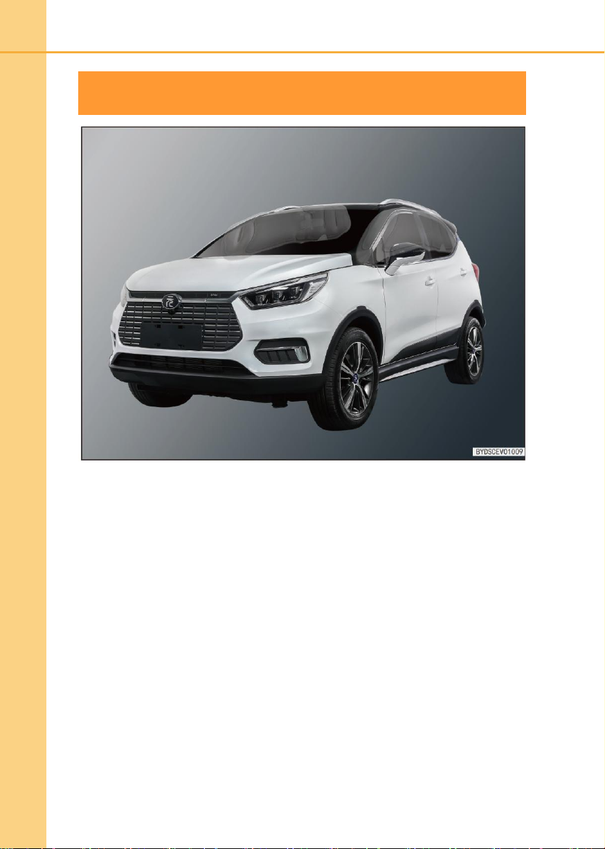
Side curtain airbag (if fitted)
If your car is equipped with a left curtain airbag and a right curtain airbag (as shown above,
the airbag is installed at the connection between the side panel and the roof and marked
with “SRS AIRBAG Air Curtain” on the A-pillar guard, B-pillar guard and C-pillar guard.)
■ When the airbag system ECU senses a moderate to severe side collision and the
airbag triggering conditions are met during driving process, the airbag will be triggered
to protect the head of the occupant on the collision side to reduce the injury.
■ In case of a side impact, generally only the airbag on the collision side can be
triggered.
■ In order to obtain the best protection from the seat side airbag, the occupant must
correctly wear the seatbelt, maintain the upright sitting attitude and be against the seat
backrest.
Page 29

1
Safety
1-2 Airbag system
29
Airbag triggering conditions and notes
■ The airbag triggering conditions are as follows: The decisive factor of the airbag
triggering in case of a collision is related to the collision energy, the type of accident,
the collision angle, the obstacle and the driving speed; in case of a special collision,
the airbag system may be triggered.
■ The airbag is not triggered in case of any accident; it will not be triggered generally in
case of a minor frontal collision, rear collision or rollover. In these cases, the driver and
the passengers wearing the seatbelts normally can be protected normally.
■ Decisive factor for the airbag triggering: It will be produced in case of a collision and
the deceleration curve obtained by the electronic control unit (ECU) and the set value
will be compared and judged comprehensively and intelligently; if the signals such as
the deceleration curve generated and detected in the collision is lower than the
relevant reference value preset in ECU, the airbag will not be triggered, even if the car
is severely deformed in the accident.
■ In the settings of ECU of BYD airbag system, the common misuses and road
conditions have been fully taken into account. However, due to various causes and
forms of collision, for your safety, please strictly follow the user manual and drive your
car correctly, to avoid any misuse; otherwise the airbag will not achieve the desired
functions.
Page 30
30
1-2 Airbag system
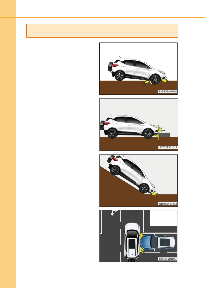
Cases when the airbag may be triggered (if fitted)
When a car across a deeper groove and
the front of the car collided the ground.
When a car collides any bump or stone
on the road side.
When the front of the car collides the
ground on a steep slope.
When a car is hit on its side by other
cars.
Page 31
1
Safety
1-2 Airbag system
31
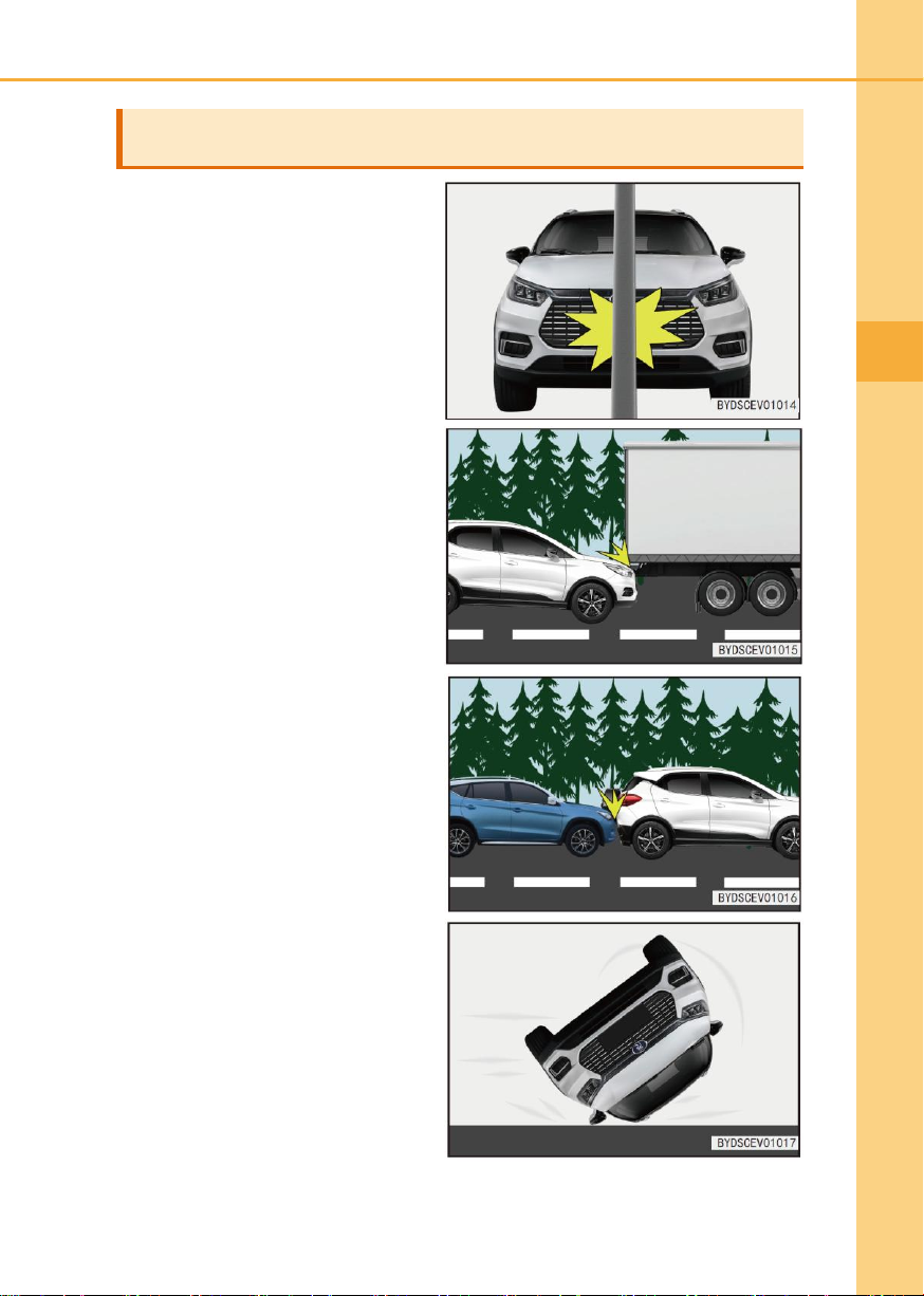
Cases when the airbag may not be triggered (if fitted)
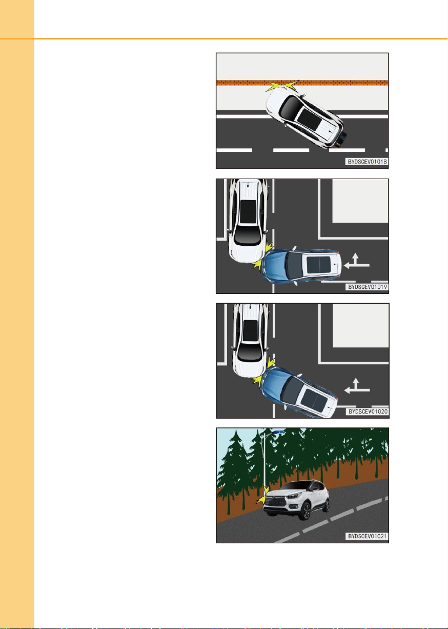
When a car collides a concrete pillar,
tree or other slender object.
Underrun into a large truck.
When the rear of a car is hit by other
cars.
When a car rolls.
Page 32
32
1-2 Airbag system
When the non-frontal of a car collides a
wall or any other car.
When any car position other than the
passenger compartment is hit on a side.
When a side of car is hit in an oblique
direction.
When a side of car collides a
column-like object.
Page 33

1
Safety
1-2 Airbag system
33
Warning
● The airbag is developed for the specific model; any changes in suspension, tire size,
bumper, chassis and other original device may adversely affect the airbag system.
Any part of the airbag system cannot be used in other models; otherwise it may
cause the airbag system fault and cause injuries
● Please fasten your seatbelt and keep your correct sitting attitude during driving
process. If you do not wear a seatbelt, your body leans forward or you are seated
incorrectly during driving process, the risk of injury may be increased when the
airbag system is triggered in case of an accident.
● The driver chest wheel should be at least 25cm away from the steering wheel during
driving process, to provide the driver with the most effective protection when the
airbag system is triggered.
● Do not stick or cover any item or make any other decorative treatment on the
steering wheel cover surface, the surface near the airbag on the right side of the
dashboard, the surfaces of A, B, and C-pillar upper guards, and the surfaces near
the knee airbag guard and the seat side airbag accessories. The airbag can be
cleaned only with a dry or slightly wetted cloth and cannot be hit hard.
● An unprotected child or a child held by an adult cannot sit in the front passenger
seat. Otherwise, when the airbag is triggered in case of an accident, it may cause
serious injury or even death.
● There should be no other passenger, animal or object within the action range of the
driver and front passenger airbags. It is very dangerous for the child held by an adult
seated in the front passenger seat.
● Any accessory, such as telephone holder, cup holder and ashtray, must not be
installed on the airbag cover or within its action range; otherwise the risk of injury will
be increased when the airbag is triggered in case of an accident.
● The side airbag and the side air curtain are triggered at a high speed and the impact
force is large, so anyone cannot lean against the door in the car equipped with the
airbag during driving process; otherwise it may cause serious injury or even death.
● Do not place any other trim or item with the action range of the side curtain, such as
windshield, side door glass, A-pillar guard, roof, B-pillar guard, C-pillar guard and
auxiliary handle; when the side curtain is triggered, the trim or item may be thrown
with the impact force from the side air curtain, or the side air curtain may not be
triggered normally, resulting in serious injury or even death.
● Do not change any component of the airbag system, including any corresponding
label. Any operation of the airbag must be performed by BYD Auto Authorized
Service Station.
● The airbag can only provide one-time accident protection. Once the airbag is
triggered or damaged, the airbag system must be replaced.
Page 34

34
1-2 Airbag system
Warning (continued)
● From the date of manufacture (the date of manufacture marked in the car
certificate), please be sure to replace the airbag system within 10 years; the
replacement work should be performed by BYD Auto Authorized Service Station. If
you have replaced one part of the airbag system before the date, please keep the
relevant replacement record; when the car is transferred, please hand it over with all
other documents to the new owner.
● When the car or the parts of airbag system are disposed, please observe the related
safety regulations and disposal procedures.
● The airbag system has strong anti-interference and anti- disturbance abilities to
anything around it. However, do not use the car in an electromagnetic environment
beyond the state permission range to avoid accidents.
● For the airbag system in the car, various misuses and common road conditions have
been fully taken into account. However, do not cause serious collision of the bottom
of the car or drive the car on harsh road conditions to avoid accidents.
● After a collision of the car, although the airbag module is not triggered and the
pre-tensioned seatbelt is not locked, the airbag computer will be encrypted in order
to protect the passengers from the high-voltage risk; it is recommended to contact
BYD Auto Authorized Service Station for inspection.
● Please read the user manual carefully. If you want to transfer or dispose your car,
please inform the new owner or the disposal organization that your car is equipped
with airbag systems and advise them to read the manual carefully.
● After the airbag system is triggered, do not directly contact with the airbag module
assembly (otherwise it may cause burns or physical discomfort); it is recommended
to contact BYD Auto Authorized Service Station for disposal. Once the airbag
system is triggered, a new one must be replaced in a timely manner.
● The front (side) airbag system is only triggered in case of a serious front (side)
collision. That the airbag system is not triggered does not mean that there is a fault
from the airbag system itself. Any improper repair or no repair of the damaged part
on the car may affect the normal operation of the airbag system.
● Do not use any seat trim to cover the inflatable port of the side airbag; otherwise
these trim may prevent the side airbags from normal deployment, resulting in
serious injury or even death.
● Do not disassemble or repair A-pillar, roof, B-pillar, and C-pillar containing curtain
airbags. These changes can cause the airbag system fault or accidental triggering of
curtain airbags, resulting in serious injury or even death.
● The manufacturer will not be responsible for any direct or indirect losses from any
damage caused by follow the above instructions.
Page 35
1
Safety
1-3 Child restraint device
35
Child restraint device
Tip
● It is strongly recommended to use the child restraint device. Some studies have
shown that it is safer to install the child restraint device in the rear seat than in the
front seat; do not install the child restraint device in the front seat.
● The seatbelts in the car is mainly designed on base of the size of the adult and are
not suitable for children; please choose the appropriate child restraint device based
on the ages and sizes of the children.
1-3 Child restraint device
Choose a suitable child restraint device based on the age and size
of your child.
Please choose a suitable child restraint device for your child. If your child has a too big size
to use the child restraint device, the child should sit in one rear seat and wear the seatbelt
normally.
When no child restraint device is used
Please normally secure the child restraint device in the seat; do not place it in the
passenger seat or in the luggage compartment freely.
Notes:
■ The seatbelt or the child restraint device must be used for restrain protection based on
the child age and size, so as to provide effective protection for the child in case of
accidents and emergency braking. Holding a child in arms is not a substitute for the
role of the child restraint device. In case of an accident, the child may be hit with the
windshield or be squeezed between you and the inside wall of the car.
■ Do not install a rear-facing child restraint device in the front passenger seat; otherwise,
the impact of rapid deployment of the front passenger airbag can cause serious injury
or even death in case of an accident.
■ In a car equipped with side airbags and side curtain airbags, even if a child is fixed in
the child restraint device, do not allow his/her head, body or any part to lean against
door, seat, front and rear pillars or the roof side beam (on deployment positions of the
side airbag or side curtain airbag). Otherwise, when the side airbag or the side curtain
airbag is triggered, the strong impact may cause serious injury or even death.
Page 36
36
1-3 Child restraint device
Installation of child restraint device
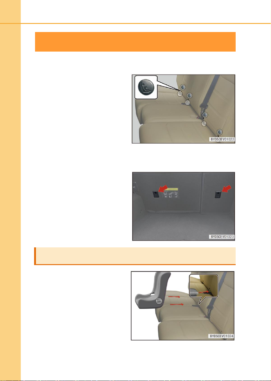
A dedicated anchor rod is provided on
the rear outer seats. (The label showing
the anchor position is attached onto the
seat)
■ An anchor holder is provided on the
rear seat.
■ If the child restraint device is
equipped with a top belt, the top
belt should be secured to the
anchor holder.
Install the child restraint device with ISOFIX steel anchors
1. Check the position of the dedicated
anchor and install the child restraint
device into the seat.
ISOFIX steel anchor (ISOFIX child restraint device)
Fixed anchor holder (for top belt)
Page 37
1
Safety
1-3 Child restraint device
37
Tip
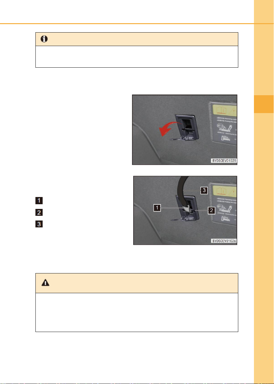
● The anchor rod is installed in the gap between the seat cushion and the seat
backrest.
3. Open the anchor holder cover.
4. Fasten the hook to the anchor
holder and tighten the top seat to
ensure its fastening.
Hook
Anchor holder
Top belt
Warning
● When using the lower anchoring device, ensure that there is no foreign object
around the anchoring device and that the seatbelt is not pinched behind the child
restraint device, to ensure that the child restraint device is securely fastened.
Otherwise, it may result in serious injury or even death in case of an emergency
braking or accident.
2. Lift up the head restraint, insert the top strap and grab of child seat between the head
restraint rods, and wind them to the back of backrest.
■ After the seat is installed, push/pull the child restraint device in different directions to
ensure that it is securely installed.
■ If the driver seat interferes with the correct installation of the child restraint device,
install the child restraint device in the rear right seat.
Page 38
38
1-3 Child restraint device
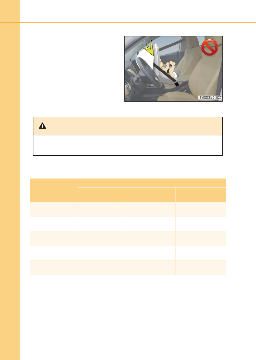
■ Do not use the rear-facing child
restraint device (child restraint
device) in the seat protected with
the front airbag (activated);
otherwise, the impact from rapid
deployment of the front passenger
airbag may cause a serious injury
or even death in case of an
accident.
Warning
● Do not allow the child to play with the seatbelt; otherwise it may cause serious injury
or even death.
Mass group
Sitting position (other position)
Front passenger
Rear outer
passenger
Rear middle
passenger
Group 0 (less than
10kg)
X U X
Group 0+ (less than
13kg)
X U X
Group I (9kg ~
18kg)
X
U/UF
X
Group II (15kg ~
25kg)
X
UF
X
Group III (22kg ~
36kg)
X
UF
X
Information on the suitability of different seating positions for the
child restraint device:
Note: The letter meanings in the form are as below:
U= General child restraint device for the mass group certification
UF= Forward-facing general child restraint device for the mass group certification
X= Seat position that does not apply to the child restraint device of the mass group
Page 39

1
Safety
1-3 Child restraint device
39
Mass group
Size
Anchor
module
ISOFIX position in the car
Front
passenger
Rear outer
passenger
Rear middle
passenger
Portable baby
cot
F
ISO/L1 X X X G
ISO/L2 X X
X
Group 0 (less
than 10kg)
E
ISO/R1 X X
X
Group 0+ (less
than 13kg)
E
ISO/R1 X X
X
D
ISO/R2 X X X C
ISO/R3 X X
X
Group I (9kg ~
18kg)
D
ISO/R2 X X
X
C
ISO/R3 X X X B
ISO/F2 X IUF
X
B1
ISO/F2X X IUF
X
A
ISO/F3 X IUF
X
Information on applicability of different ISOFIX positions for ISOFIX
child restraint device
Note 1: For child restraint device that do not conform to ISO/XX size category identification
(A-G), the car manufacturer should specify the specific ISOFIX child restraint device
recommended for each seating position for the applicable mass group.
Note 2: The letter meanings in the form are as below:
IUF= Forward-facing general ISOFIX child restraint device for the mass group certification
X= ISOFIX position that does not apply to ISOFIX child restraint device of the mass group
and/or the size category
Page 40
40
1-4 Anti-theft system
Anti-theft system
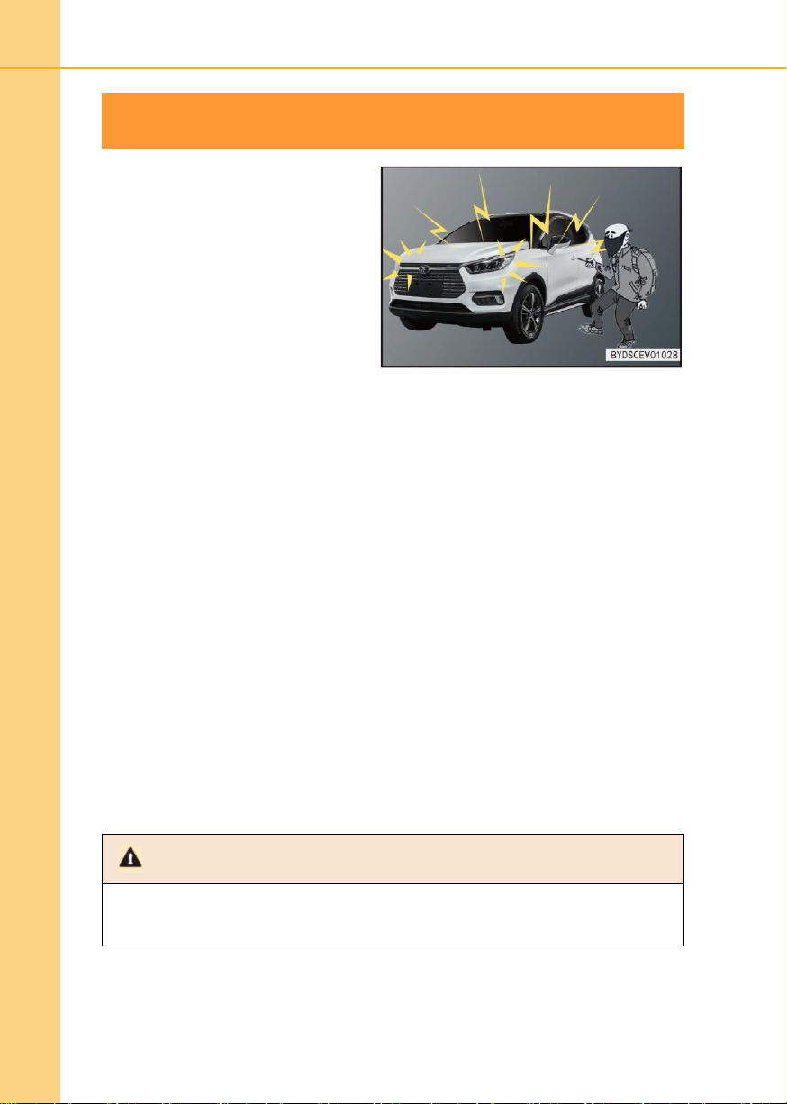
In order to prevent your car from theft, if
any door is opened under anti-theft
status, the system will send an alarm,
and the turn signal will flash.
System settings
1. Turn the power supply switch to
“OFF” position.
2. Let all passengers get off.
3. Lock all doors. When all doors are
locked, the anti-theft indicator will
be on and the anti-theft system will
be set automatically after 10s.
Note
● Do not modify the anti-theft system in modification or addition way. Such changes
may result in the system fault.
1-4 Anti-theft system
4. After the automatic settings are performed, leave your car. Since the system can be
activated by unlocking the door from the inside of the car, it is prohibited to stay in the
car when setting the system.
Trigger alarm
■ The system will send an alarm in following cases:
● When the smart key access function is not used, but any door is unlocked or the
front hatch is opened.
● When the smart key activation function is not used but the car is powered up.
Cancel alarm
■ The alarm can stop in the following ways:
● Unlock the doors with the wireless remote control.
● Unlock the doors with the micro switch.
● Press “Start/Stop” button of the key in the car.
● Remotely start the vehicle.
Page 41

1
Precauciones de seguridad
Dashboard
2
2-1 Dashboard ......................................... 42
Dashboard view .................................. 42
Indicator/ warning indicator ................ 43
Page 42
42
2-1 Dashboard
Dashboard view
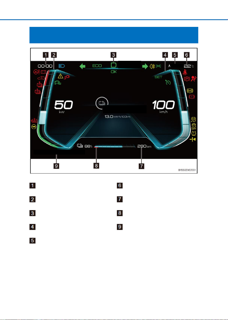
Time
Ambient temperature
Power meter
Driving range
Gear position
Electricity meter
Speedometer
Total travel mileage
Orientation
288880km of total mileage
Average electrical consumption
in latest 50km
Standard
feedback
Southeast
2-1 Dashboard
Page 43
2
Dashboard
2-1 Dashboard
43
Indicator/ warning indicator
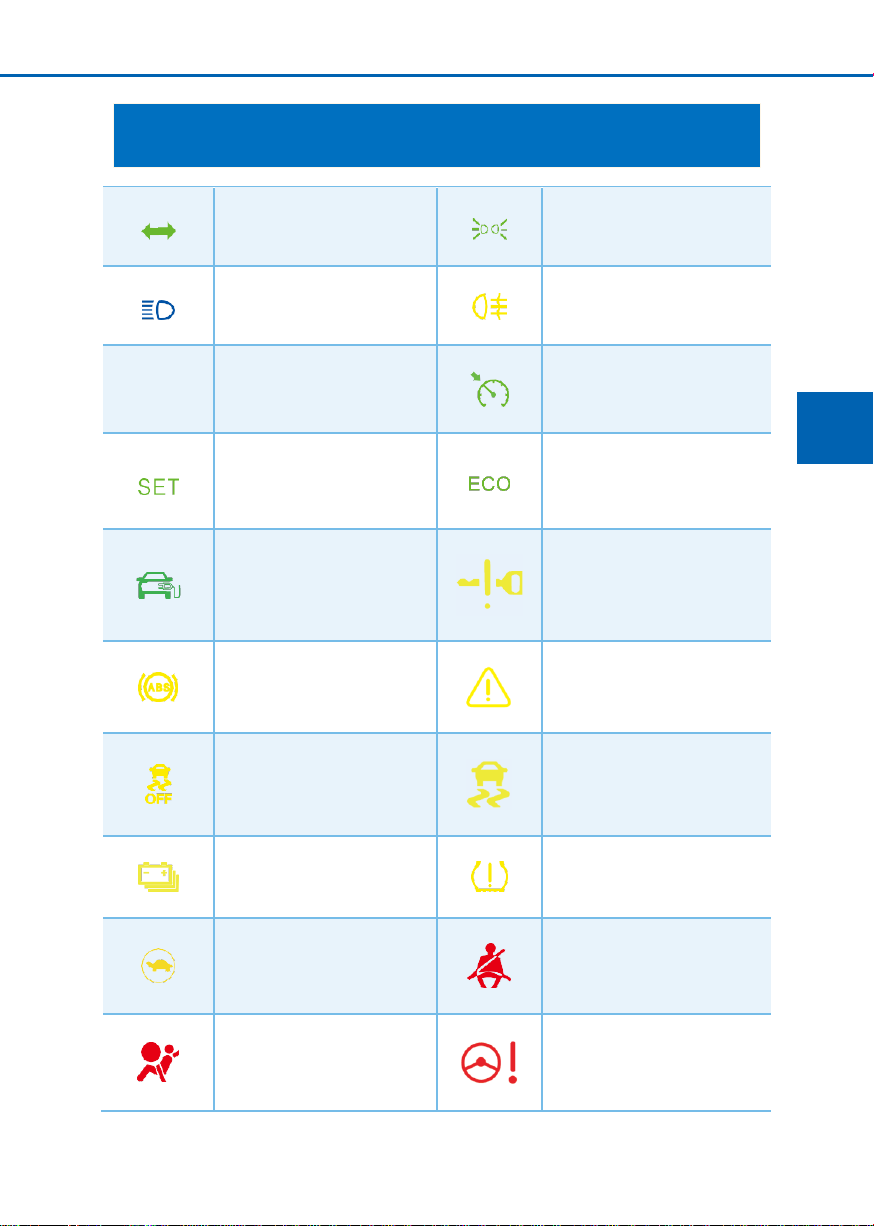
Turn indicator
Small light indicator
High beam indicator
Rear fog light indicator
OK
OK indicator
Cruise control main indicator
lamp
Cruise control indicator
ECO indicator
Discharge indicator (if fitted)
Smart key system warning
indicator
ABS fault warning indicator
Main alarm indicator
ESP OFF warning indicator
ESP fault warning indicator
Power battery low-voltage
indicator
Tire pressure fault warning
indicator
Drive power limit warning
indicator
Seatbelt not-fastening
indicator
SRS fault warning indicator
Steering system malfunction
indicator lamp
Page 44
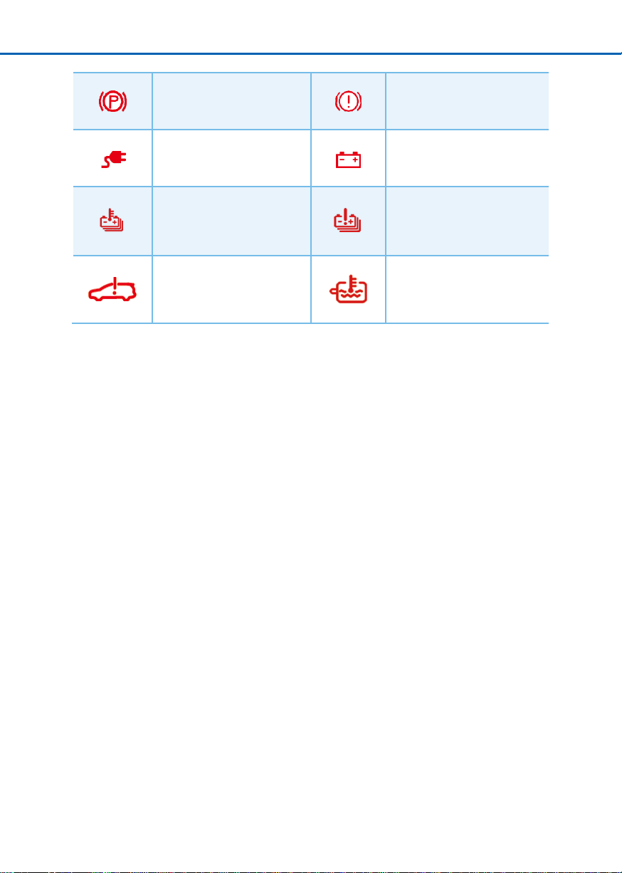
44
2-1 Dashboard
Electronic parking status
indicator
Parking system fault warning
indicator
Power battery charge
connection indicator
Charge system warning
indicator
Power battery overheat
warning indicator
Power battery overheat
warning indicator
Power system fault warning
indicator
Motor coolant temperature
too-high warning indicator
Page 45

2
Dashboard
2-1 Dashboard
45
Instruction to the indicators
Smart key system warning indicator
■ Press “Start/Stop” button. If there is no electronic smart key at the time, the warning
indicator will be turned on and held a few seconds, the buzzer will sound once, and
“No Key Detected” will be displayed on the dashboard.
■ If the electronic smart key is taken into the car within a few seconds when the warning
indicator is on, the warning indicator will be turned off and the car can be powered up.
■ If “Start/Stop” button is pressed with an electronic smart key, the warning indicator will
not be turned on and the car can be powered up.
■ If the warning indicator flashes after pressing “Start/Stop” button, it indicates that the
key battery is low-voltage.
ABS fault warning indicator
■ When the power supply is in “OK” position, the warning indicator will be turned on. If
the anti-lock brake system is operated normally, the indicator will be turned on and
then turned off after a few seconds. Thereafter, if the system is faulty, the indicator will
be turned on again until the fault is eliminated.
■ When ABS fault warning indicator is turned on (the parking brake fault warning
indicator is turned off), the anti-lock brake system cannot be operated but the brake
system can be operated normally.
■ When ABS fault warning indicator is turned on (the parking brake fault warning
indicator is turned off), the wheels will be locked during emergency braking or braking
on a slippery road because the anti-lock braking system cannot be operated.
■ In any of the following cases, it indicates that a component monitored with the warning
indicator system is faulty, it is recommended to contact BYD Auto Authorized Service
Station for inspection as soon as possible.
● When the power supply is in “OK” position, the warning indicator will not be turned
on or always on continuously.
● The warning indicator will be turned on during driving process.
● A short flashing of the warning indicator during operation does not indicate a fault.
Page 46

46
2-1 Dashboard
Tip
● If the parking brake fault warning indicator is turned on and ABS fault warning
indicator is still on, it is recommended to park the car in a safe place and contact
BYD Auto Authorized Service Station immediately.
■ ABS has a self-test function. In case of any fault, the anti-lock braking indicator on the
dashboard will be turned on. It is recommended to contact BYD Auto Authorized
Service Station for inspection as soon as possible.
■ If ABS (anti-lock brake system) indicator and the brake system indicator are turned on
at the same time and the parking brake is fully released, it indicates that the front and
rear wheel brake force distribution system is faulty. It is recommended to contact BYD
Auto Authorized Service Station for inspection as soon as possible.
■ If the brake pedal is not operated normally as following, some measures must be
taken immediately: the brake pedal is depressed deeper and the braking distance is
longer. The car should be switched to the low-speed gear, to lower the driving speed
and safely park it to the side of the road. The driving is very dangerous due to the long
parking distance. It is recommended to park the car immediately and contact BYD
Auto Authorized Service Station for inspection as soon as possible.
ESP fault warning indicator
■ When the power supply is in “OK” position, the warning indicator will be turned on and
turned off after a few seconds, which indicates that ESP system is operated normally.
In case of a system fault, the warning indicator will be always on continuously until the
system fault is eliminated.
■ When ESP fault warning indicator flashes during driving process, it indicates that ESP
system is operated normally.
■ When ESP fault warning indicator is turned on (ABS fault warning indicator and
parking brake fault warning indicator is turned off), ESP car stability control may be
faulty, but the anti-lock braking system and the brake system will still be operated
normally.
■ When ESP fault warning indicator is turned on (ABS fault warning indicator and
parking brake fault warning indicator are turned off), because the car stability control
system is not operated, the car will be under very instable status during emergency
turns and emergency avoidance of front obstacles.
■ In any of the following cases, it indicates that a component monitored with the warning
indicator system is faulty, it is recommended to contact BYD Auto Authorized Service
Station for inspection as soon as possible.
● When the power supply is in “OK” position, the warning indicator will not be turned
on or be always on.
● The warning indicator is always on during driving process.
● A short flashing of the warning indicator during operation does not indicate a fault.
Page 47
2
Dashboard
2-1 Dashboard
47
Tip
● If ABS fault warning indicator and the brake system warning indicator are turned on,
but ESP fault warning indicator is always on, it is recommended to park the car in a
safe place and contact BYD Auto Authorized Service Station for inspection
immediately.
● In this case, when the brake is applied, the car will extremely unstable and the car
anti-lock control system will not be operated completely.
Tip
● If ESP OFF warning indicator is turned on, the car must be driven carefully at a low
speed during emergency turns and avoiding sudden obstacles. In this case, when
the brake is applied, ESP system function will not be operated, and the car will be
under unstable status.
● During driving process, if the warning indicator flashes, it indicates that the system
is operated normally.
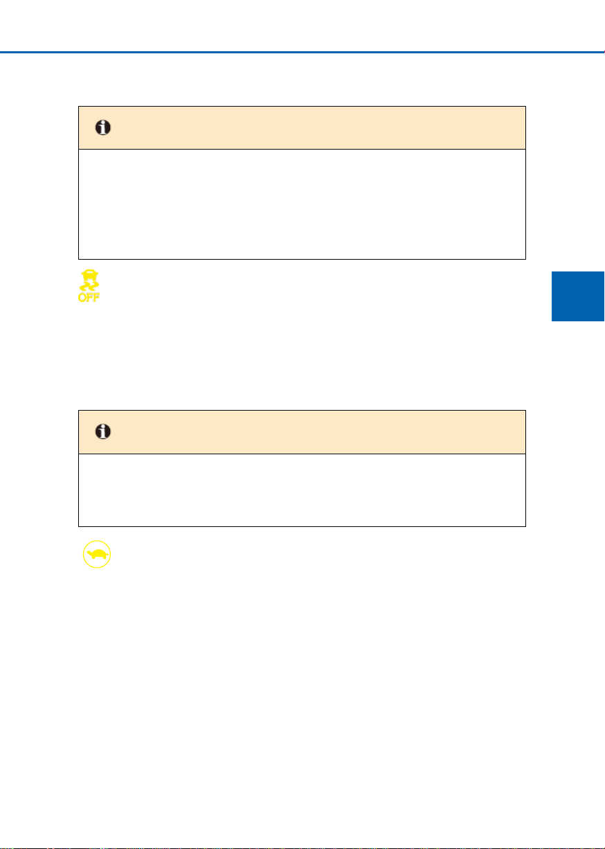
ESP OFF warning indicator
■ When the power supply is in “OK” position, the warning indicator will be turned on and
turned off after a few seconds.
■ When “ESP OFF Switch” is pressed, the indicator will be always on and the stability
control system will be not operated. When “ESP OFF Switch” is pressed again, the
indicator will be turned off and the stability control system will be returned to the
normal operation.
Drive power limit warning indicator
When the motor power is limited, the warning indicator will be turned on.
Page 48

48
2-1 Dashboard
Tire pressure fault warning indicator
■ When the power supply is in “OK” position, the warning indicator will be turned on. If
the tire pressure monitoring system is operated normally, the warning indicator will be
turned off after a few seconds. Thereafter, if the system is faulty, the warning indicator
will be turned on again.
■ When the tire pressure fault warning indicator is turned on or flashes, “Please check
the tire pressure monitoring system” is displayed on the dashboard, and “---” value is
displayed on the tire pressure display interface, it indicates that the tire pressure
system is faulty.
■ When the tire pressure fault warning indicator flashes rapidly and one or more values
on the tire pressure display interface of the dashboard are red, it indicates that the
corresponding tire is in a rapid leakage status.
■ When the tire pressure fault warning indicator is always on and the one or more values
on the tire pressure display interface of the dashboard are yellow, it indicates that the
corresponding tire is under low- voltage status.
In any of the above cases, it is recommended to contact BYD Auto Authorized Service
Station for inspection as soon as possible.
Seatbelt not-fastening indicator
The indicator is used to remind the driver and the passengers to fasten their seatbelts.
When the power supply is in “OK” position, if the seatbelt is not fastened, the seatbelt
not-fastening indicator will be turned on until the driver and the passengers fasten their
seatbelts; otherwise the indicator will be always on.
■ When the power supply is in “OK” position, the warning indicator will be turned off after
■ In any of the following cases, it indicates that a component monitored with the warning
SRS fault warning indicator
a few seconds of self-test, it indicates that the airbag system is operated normally. The
warning indicator system is used to monitor the airbag ECU, collision sensor, inflator,
warning indicators, wiring, and power supply.
indicator system is faulty, it is recommended to contact BYD Auto Authorized Service
Station for inspection as soon as possible.
● When the power supply is in “OK” position, the warning indicator will not be turned
on or be always on.
● The warning indicator is turned on or flashes during driving process.
Page 49
2
Dashboard
2-1 Dashboard
49
Tip
● When turning the steering wheel, the sound of the motor operation (“Buzzing”) will
be sent. The does not mean a fault.
Warning
● If EPS fault warning indicator is turned on, it is recommended to park the car in a
safe place and contact BYD Auto Authorized Service Station for inspection
immediately. In this case, the steering operation will be very heavy and the steering
wheel should be held during driving process.
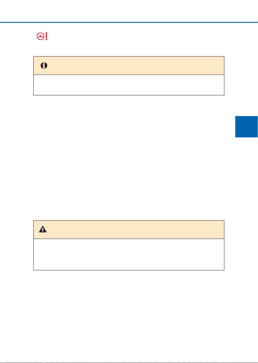
EPS fault warning indicator
EPS is equipped with a motor to reduce the force required to turn the steering wheel.
In the following two cases, the steering system warning indicator is not turned on,
but the steering feel is heavy, which does not mean a fault:
■ When turning the steering wheel for a long time under parking status
● If the steering wheel is turned for a long time under parking status, the
■ When the battery is low-voltage
performance of EPS will be reduced to prevent a heavy operation of the steering
wheel due to the system overheating. In this case, do not turn the steering wheel
frequently, must park the car and turn the power supply to “OFF” position, to
return it to normal operation within 10min.
● EPS minimum operation voltage is 9V. When the battery voltage is below 9V,
EPS will not provide the steering assist. In this case, must check the battery
conditions and charge or replace the battery if necessary.
● If the power supply is returned to “OFF” position, EPS system may not provide the
steering assist; therefore, do not return the power supply to “OFF” position during
driving process. If the power supply is returned to “OFF” position during driving
process, please hold the steering wheel, park the car in a safe place and contact
BYD Auto Authorized Service Station for inspection immediately.
Page 50
50
2-1 Dashboard
Tip
■ Do not continue the driving when the brake fluid level is too low.
■ In any of the following cases, it is recommended to park the car in a safe place and
contact BYD Auto Authorized Service Station.
● When the power supply is in “OK” position, the indicator cannot be turned off
even if the parking brake is released. In this case, the brake may not be applied
normally and the parking distance will be too long. Depress the brake pedal
hard to park the car.
● When “ABS” warning indicator is turned on, the brake system warning indicator
is still on. In this case, not only the anti-lock brake system cannot be operated,
but also the brake system is also unstable, to require the careful driving.
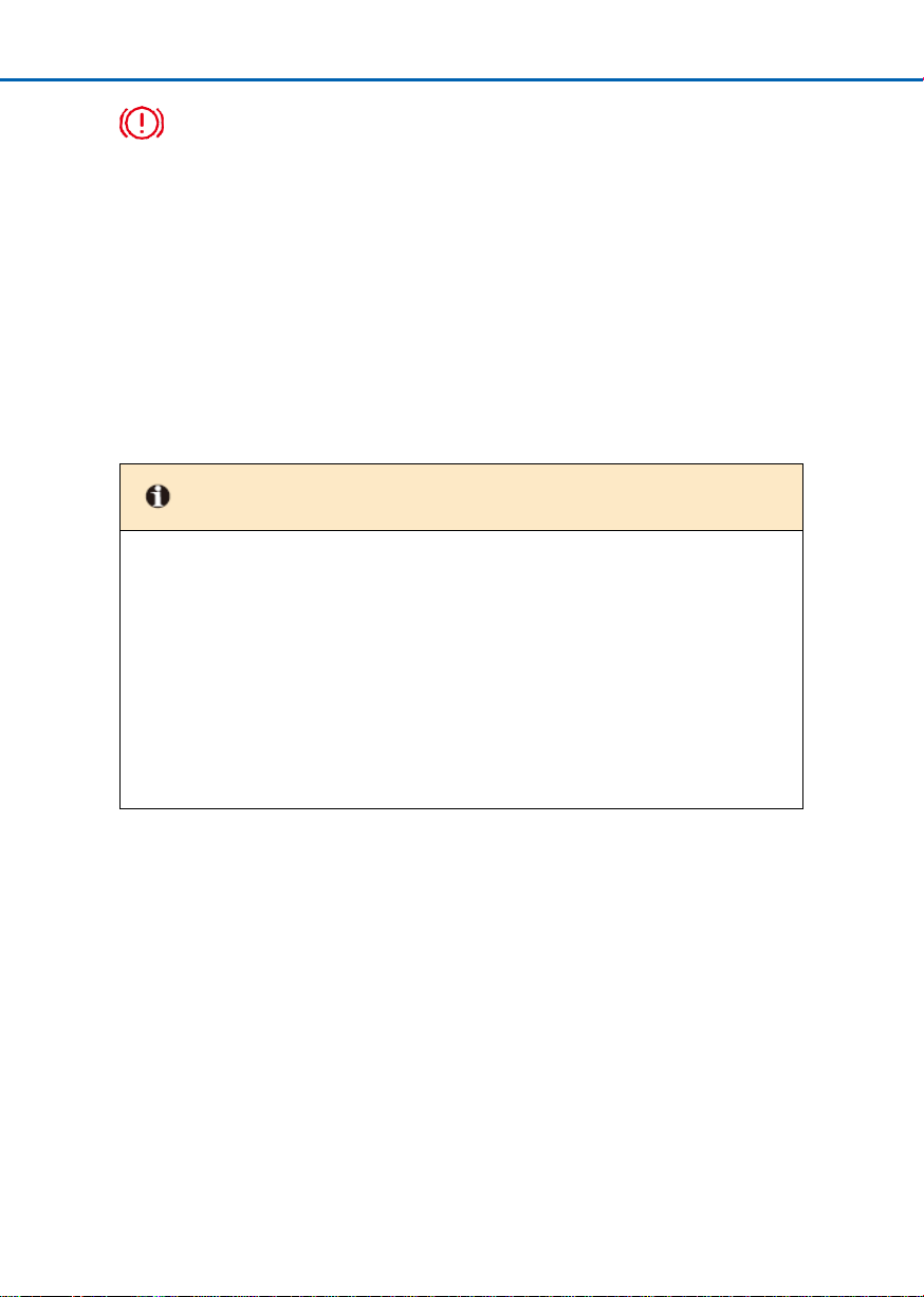
Parking system fault warning indicator
When the power supply is in “OK” position, the indicator will be turned on under the
following cases.
■ When the brake fluid level is too low;
■ When the parking brake is applied;
■ When the vacuum pressure is faulty;
■ When EBD (braking force distribution) is faulty;
■ When the electronic parking brake (if fitted) is faulty;
■ Others.......
During operation, if the warning indicator flashes, it does not indicate a fault.
Page 51

2
Dashboard
2-1 Dashboard
51
Charge system warning indicator
■ The indicator is used to indicate a charge system fault during the charge process.
■ The indicator is used to indicate a discharge system fault during the discharge
process.
■ The indicator is used to indicate the operating status of DC module and battery module
when the charge or discharge operation is not performed.
■ If the indicator is turned on during driving process, there may be a fault from DC
system or battery system. It is recommended to turn off the air conditioning, fan, radio,
and etc. and drive the car directly to the nearest BYD Auto Authorized Service Station
for repair.
Power battery overheat warning indicator
■ If the indicator is turned on, it indicates that the power battery temperature is too high
and should be parked for cooling.
■ The power battery may be overheated under the following operating conditions, such
as:
● Long-time long-distance climbing under hot conditions.
● Long-time intermittent driving, frequent acceleration and sudden braking, or
long-period driving.
Power battery fault warning indicator
■ When the power supply is in “OK” position, the warning indicator will be turned on. If
the power battery system is operated normally, the indicator will be turned off after a
few seconds. If the system is faulty, the indicator will be turned on again. It is
recommended to contact BYD Auto Authorized Service Station for inspection
immediately.
■ In any of the following cases, it indicates that a component monitored with the warning
indicator system is faulty, it is recommended to contact BYD Auto Authorized Service
Station for inspection as soon as possible.
● When the power supply is in “OK” position, the indicator will be always on.
● If the indicator is always on or flashes during driving process.
Page 52
52
2-1 Dashboard
Warning
● Do not drive the car when the warning indicator is turned on; it is recommended to
contact BYD Auto Authorized Service Station for inspection as soon as possible.
Power system fault warning indicator
■ If the power system is fault, the warning indicator will be turned on.
■ In any of the following cases, it indicates that a component monitored with the warning
indicator system is faulty, it is recommended to contact BYD Auto Authorized Service
Station for inspection as soon as possible.
● When the power supply is in “OK” position, the warning indicator will be always on
continuously.
● The warning indicator will be turned on during driving process.
■ During operation, if the warning indicator flashes, it does not indicate a fault.
Motor coolant temperature too-high warning indicator
■ If this warning lamp turns on, it indicates over-high coolant temperature. Please
immediately park the vehicle in a safe place to cool down the motor. It’s recommended
to contact a BYD Auto Authorized Service Station.
Page 53

1
Precauciones de seguridad
Controller
Operations
3
3-1 Key and door .................................... 54
Key ..................................................... 54
Lock/unlock the door .......................... 57
Smart access and start system .......... 61
Child lock ............................................ 65
3-2 Seat .................................................... 66
Front seat adjustment ......................... 66
Rear seat folding ................................ 68
Headrest ............................................. 69
3-3 Steering wheel .................................. 70
Steering wheel adjustment ................. 70
3-4 Switch ................................................ 71
Light switch ......................................... 71
Wiper switch ....................................... 77
Front left door switch assembly .......... 81
Passenger window control switch ...... 84
Emergency warning indicator switch
........................................................... 85
Lighting adjustment switch group ....... 85
Mode switch group ............................. 86
Steering wheel switch group .............. 87
Sunroof switch (if fitted) ...................... 95
B-call/E-call switch(if fitted) ................ 97
Indoor light switch ............................... 98
Page 54
54
3-1 Key and door
Key
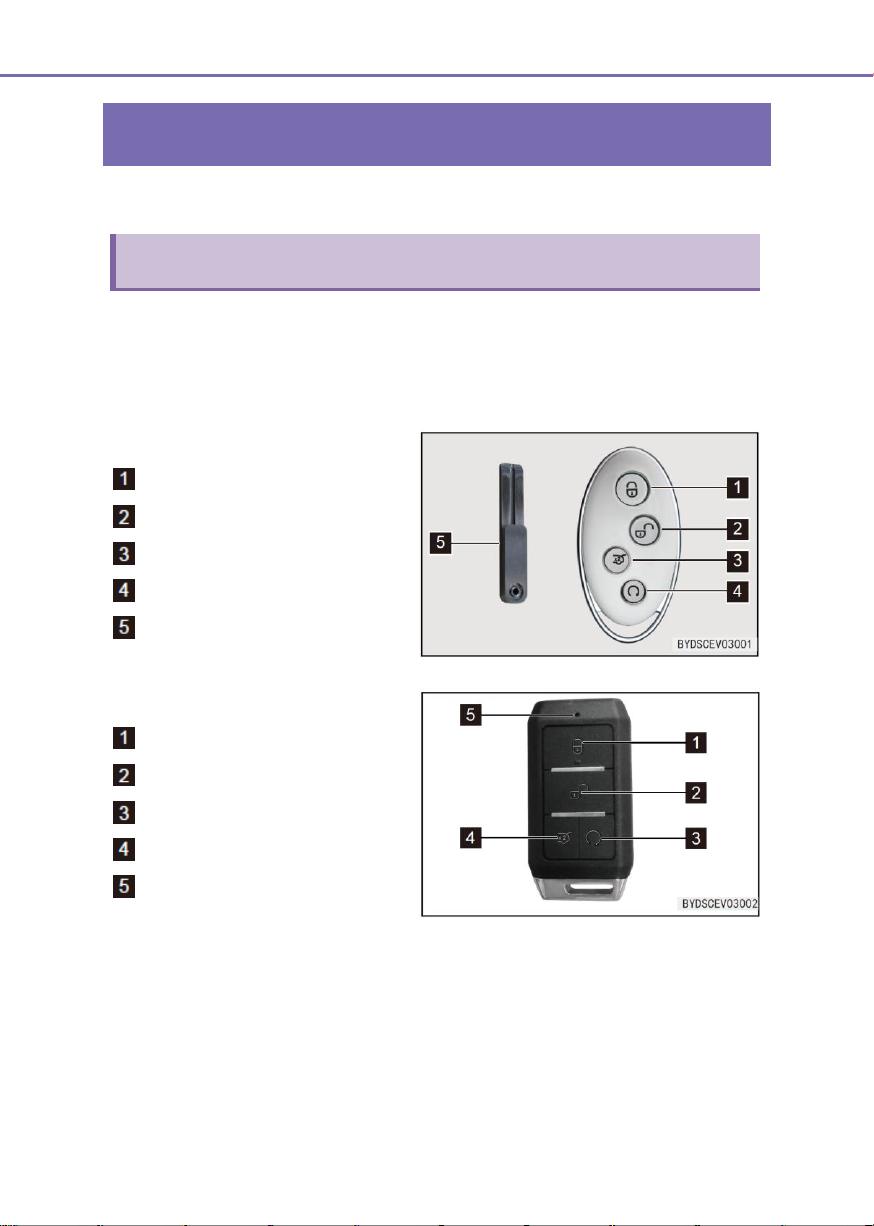
Electronic smart key
Configuration 1
“Lock” button
“Unlock” button
“Back Door Unlock” button
“Start/Stop” button
Mechanical key
Configuration 2
“Lock” button
“Unlock” button
“Start/Stop” button
“Back Door Unlock” button
Indicator lamp
3-1 Key and door
The key equipped for your car can be used to unlock/lock the doors and start the car. The
keys include the smart key and the mechanical key (mounted in the smart key).
Electronic smart key – When the front left door micro switch (the black button on the outer
handle) is pressed by the driver carrying the electronic smart key, all doors will be
unlocked/locked; when the back door micro switch (the button on the right tail light trim) is
pressed, the back door will be opened; the door unlocking/locking, back door opening or
car finding can be performed remotely by pressing the button on the remote control key.
Page 55

3
Controller Operations
3-1 Key and door
55
Note
■ The electronic smart key is an electronic component and the following instructions
should be followed to prevent its damage:
● Do not leave the keys at high temperature, such as on the dashboard exposed
to the sun in summer.
● Do not disassemble the keys without permission.
● Do not strike other objects with the key or drop the key.
● Do not immerse the key in water or wash it in an ultrasonic cleaner.
● Do not put the smart key together with a device with electromagnetic waves,
such as a mobile phone.
● Do not attach any object (such as metal seals) that will affect the
electromagnetic wave onto the smart key.
● A pare key can be registered for the same car. For more details, please contact
BYD Auto Authorized Service Station.
■ If the electronic smart key cannot be used to operate the doors within the normal
distance, or the indicator on the key cannot be turned on or be instable:
● Check the surroundings for radio stations or radio transmitters that may
interfere with the normal operation of the electronic smart key.
● The battery power of the electronic smart key may be exhausted. Check the
battery in the electronic smart key. If the battery is need for replacement, it is
recommended to contact BYD Auto Authorized Service Station.
■ If the electronic smart key is lost, it is recommended to contact BYD Auto Authorized
Service Station as soon as possible, to avoid a theft or accident.
■ Do not change the transmission frequency and increase the transmission power
(including the addition of the transmission frequency amplifier); do not use the
external test antenna or any other transmission test antenna.
■ Do not cause harmful interference on various legal radio communication services
when using the smart key; if any, must shut down its use immediately and take
measures to eliminate the interference before its re-use.
■ The micro power radio device must be used away from interference from various
radio services or radiated interference from industrial, scientific and medical
applications.
■ Do not use the smart key near airplanes and airports.
Page 56
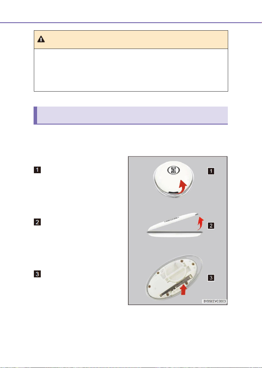
56
3-1 Key and door
Note (continued)
■ Any person implanted with pacemaker or cardiac defibrillator should be away from
the test antennas of the smart access and start system, as the electromagnetic
wave can affect the normal use of such devices. Any user with other electronic
medical devices should also consult the manufacturer for the use information under
the influence of electromagnetic wave. The electromagnetic wave may have
unknown consequences for the use of such medical devices.
Mechanical key
Configuration 1
Place your finger in the middle hole.
Open the back cover.
Remove the mechanical key
Mechanical key (In electronic intelligent key) - It can be used to unlock and lock the driver
door. When it’s not in use, ensure to place back the mechanical key and install the rear
cover of electronic intelligent key or insert into the electronic intelligent key.
Page 57
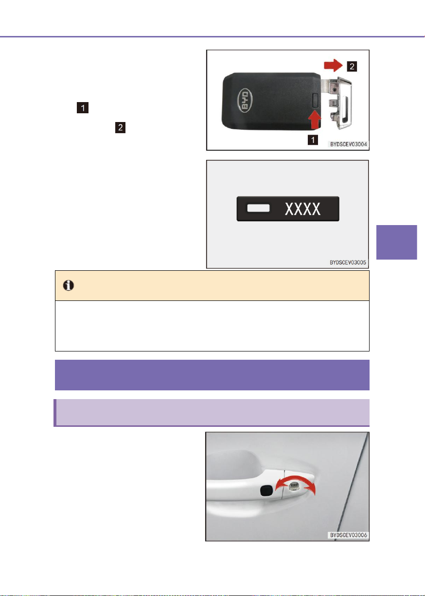
3
Controller Operations
3-1 Key and door
57
Configuration 2
To use the mechanical key in the
electronic intelligent key, as shown in
right diagram, push down the small
block on the electronic key and take
out the mechanical key along the
direction of arrow .
Mechanical key number plate
■ The mechanical key number should
be indicated on the number plate. If
the key is lost or spared, it is
recommended to contact BYD Auto
Authorized Service Station to copy
it with the key number.
Tip
● Place the number plate in a safe place, such as a travel bag; do not put it in the car.
● It is recommended that the user records the key number and stores it in a safe
place.
Lock/unlock the door
Mechanical key lock/unlock
Lock and unlock with a
mechanical key
Insert the key into the lock hole and turn
it.
■ Unlock: Turn the key clockwise
■ Lock: Turn the key
counterclockwise
Page 58
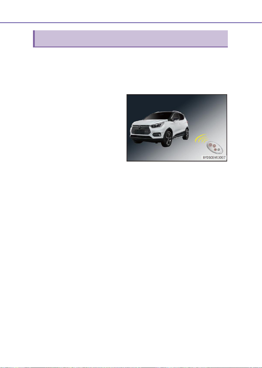
58
3-1 Key and door
Smart key lock/unlock
Lock:
■ If pressing “Lock” button; all doors
will be locked at the same time.
When all doors, the front hatch and
the back door are closed, the
exterior rearview mirrors will be
folded (if fitted), and the turn signal
will flash once.
■ If any of the doors, the front hatch
or the back door is not closed, the
exterior rearview mirrors will not be
folded (if fitted), the turn signal will
not flash and the alarm will sound
once.
■ The wireless remote control is designed to unlock or lock all doors and perform
additional functions within the range of about 20m.
■ When the driver carrying the registered smart key enters the active area, if pressing
“Unlock/Lock” button on the key slowly and firmly, all doors will be locked and
unlocked.
Unlock:
■ If pressing “Unlock” button, all doors will be unlocked at the same time, and the turn
signal will flash twice.
■ If the power supply is in “Start” position, the doors cannot be unlocked/locked with
“Unlock” or “Lock” button.
■ When unlocking all doors with an electronic smart key, even if any door is not opened,
the indoor light may be turned on (it will be turned on when its switch is turned to “Door
Control” position) and then turned off after 16s.
■ After unlocking all doors with an electronic smart key, any door should be opened
within 30s. Otherwise, all doors will be re-locked automatically.
■ The four-door anti-pinch function is provided: If pressing and holding “Lock” or
“Unlock” button, the lock or unlock function will not be repeated; only releasing and
pressing “Lock” or “Unlock” button again, the function can be repeated. If pressing and
holding “Lock” button, the four door glasses will be raised automatically.
Open the back door with the remote control key
If double-clicking “Back Door Unlock” button on the smart key, the back door will be opened
and the turn signal will flash twice.
Page 59
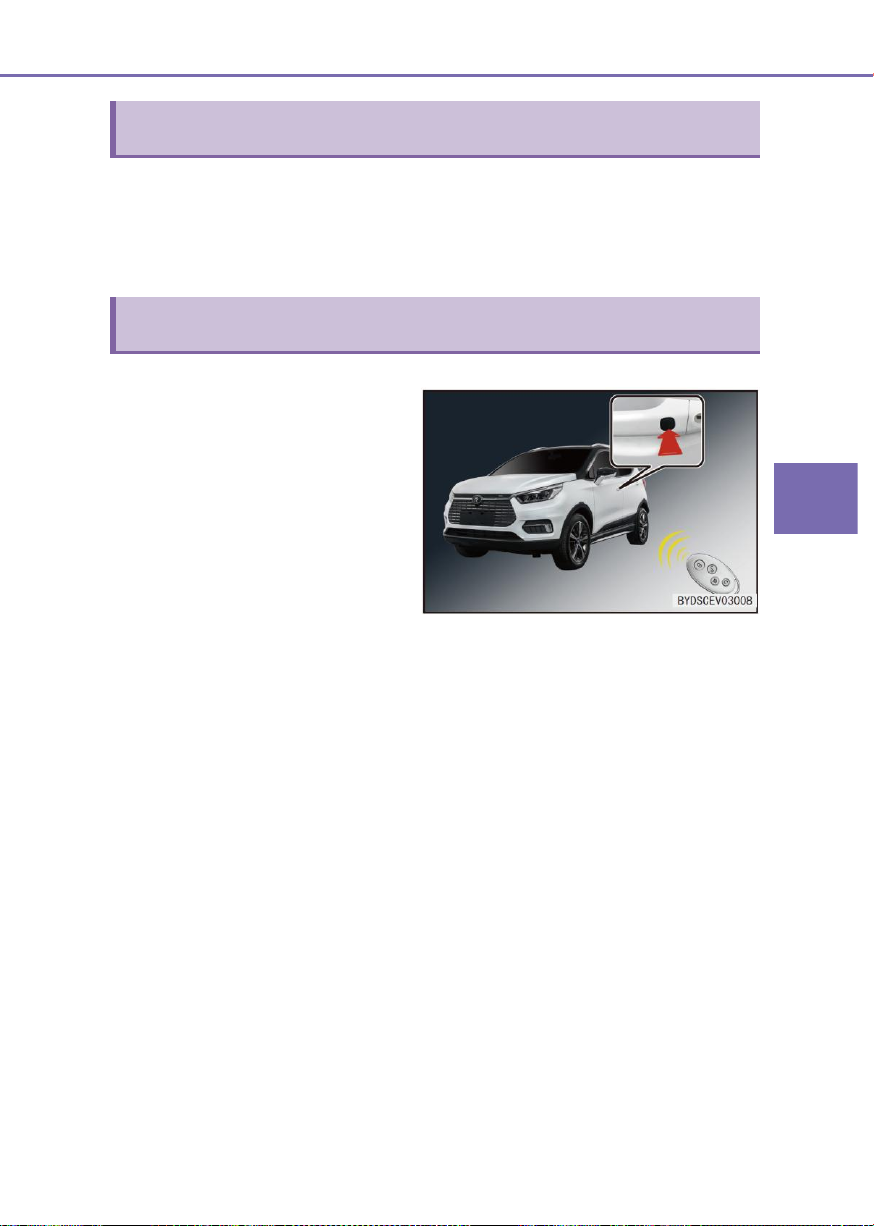
3
Controller Operations
3-1 Key and door
59
Car search operation
Micro switch lock/unlock
Lock operation
■ When the door is unlocked, if the
driver carrying the valid smart key
presses micro switch button on the
outside door handle slowly and
firmly. All doors will be locked at the
same time, the exterior rearview
mirrors will be folded (if fitted), and
the turn signal will flash once.
● When the power switch is in
“non-OFF” position, the doors
will not be locked by pressing
the micro switch.
■ When the car is under anti-theft status, if pressing “Lock” button, a beep will sound and
the turn signal will flash 15 times. When you cannot confirm the position of your car,
the specific position of your car can be searched with the function.
■ When the car is under “Search” status, if pressing “Lock” button again, the next search
status will be entered again.
■ When the door is unlocked, if the driver carrying the valid smart key presses micro
switch button on the outside door handle slowly and firmly. All doors will be unlocked,
the exterior rearview mirrors will be unfolded (if fitted), and the turn signal will flash
twice.
■ After using the unlock function, any door can be opened within 30s. Otherwise, all
doors will be re-locked automatically.
● When the doors are unlocked with the smart access and start system, must check
the doors for locking before pulling the door handle.
In the following cases, the doors will not be unlocked/ locked by
Unlock operation
pressing the micro switch button:
● When any door is opened or closed and at the same time the micro switch button
is pressed.
● When the power switch is not turned off.
● When the power switch is in “OFF” position.
● When the key is left in the car.
Page 60
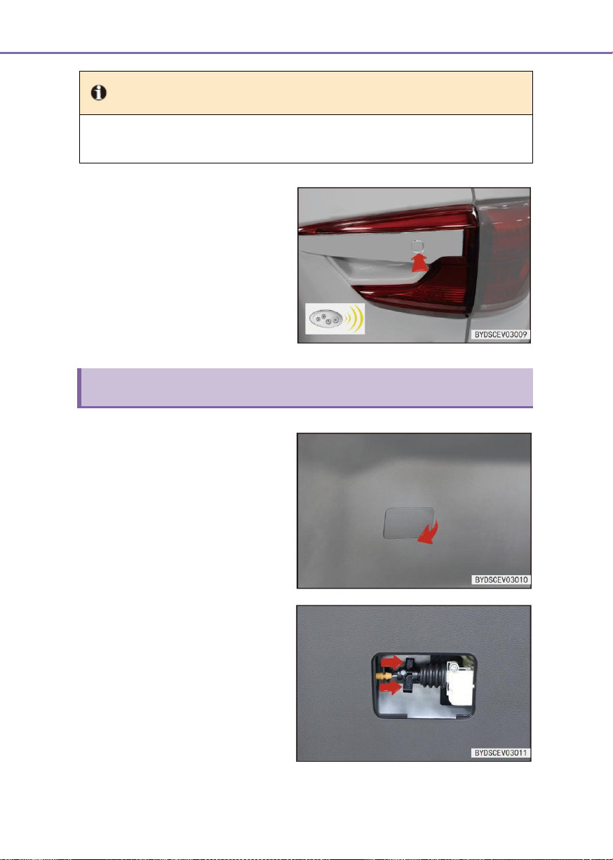
60
3-1 Key and door
Tip
● If the electronic smart key is too close to the outer door handle or the window, the
access function may not be activated.
Open the back door with the
micro switch
■ The driver carrying the valid smart
key should press the micro switch
button on the back door slowly and
firmly to open the back door.
Emergency unlock the back door
1. Remove the back door lock cover
access cover from the back door
guard.
2. Toggle the unlock button to unlock
the back door as shown.
Page 61
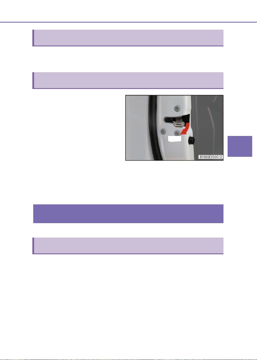
3
Controller Operations
3-1 Key and door
61
Lock/unlock the central door lock
Emergency lock all doors with the mechanical key
■ When the central control lock is
faulty, please lock the front left door
with the mechanical key, turn the
emergency locking buttons of the
other doors to the locking status
with the key, and then close the
doors; at the time, all doors will be
locked and cannot be opened with
the door handles.
■ When the doors are unlocked, first
unlock the front door with the
mechanical key and enter the car,
unlock other doors by operating the
other inside door buttons, and then
pull the outside door handles to
open the doors.
Smart access and start system
Access and start functions
Lock
Unlock and lock all doors with the central door lock switch
See “Front left Door Switch Assembly” in this chapter.
The driver carrying an electronic smart key can unlock or lock the doors and start the car.
Access function
It can be used to unlock and lock the doors.
Page 62
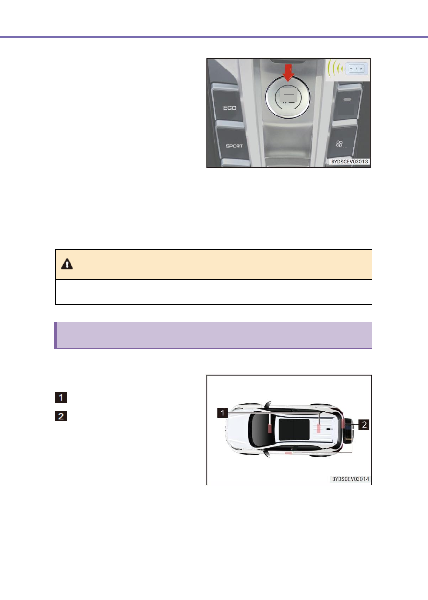
62
3-1 Key and door
Start function
When the electronic smart key is in the
car, it can be used to start and park the
car.
If “Start/Stop” button is pressed, that
the start function cannot be operated
normally may be caused by the
following reasons:
■ If the smart key is not operated
normally, the smart key battery may
be exhausted and should be
replaced as soon as possible.
Note
● Do not touch “Start/Stop” button during driving process.
Antenna position
Test antenna position
Test antenna located in the car
Test antenna located outside the
car
ON
OFF
Start
Stop
Automatic
■ The car is started repeatedly within a short time. Wait for 10s and then start the car as
possible.
■ When the steering wheel is locked, press “Start/Stop” button and gently shake the
steering wheel.
Page 63
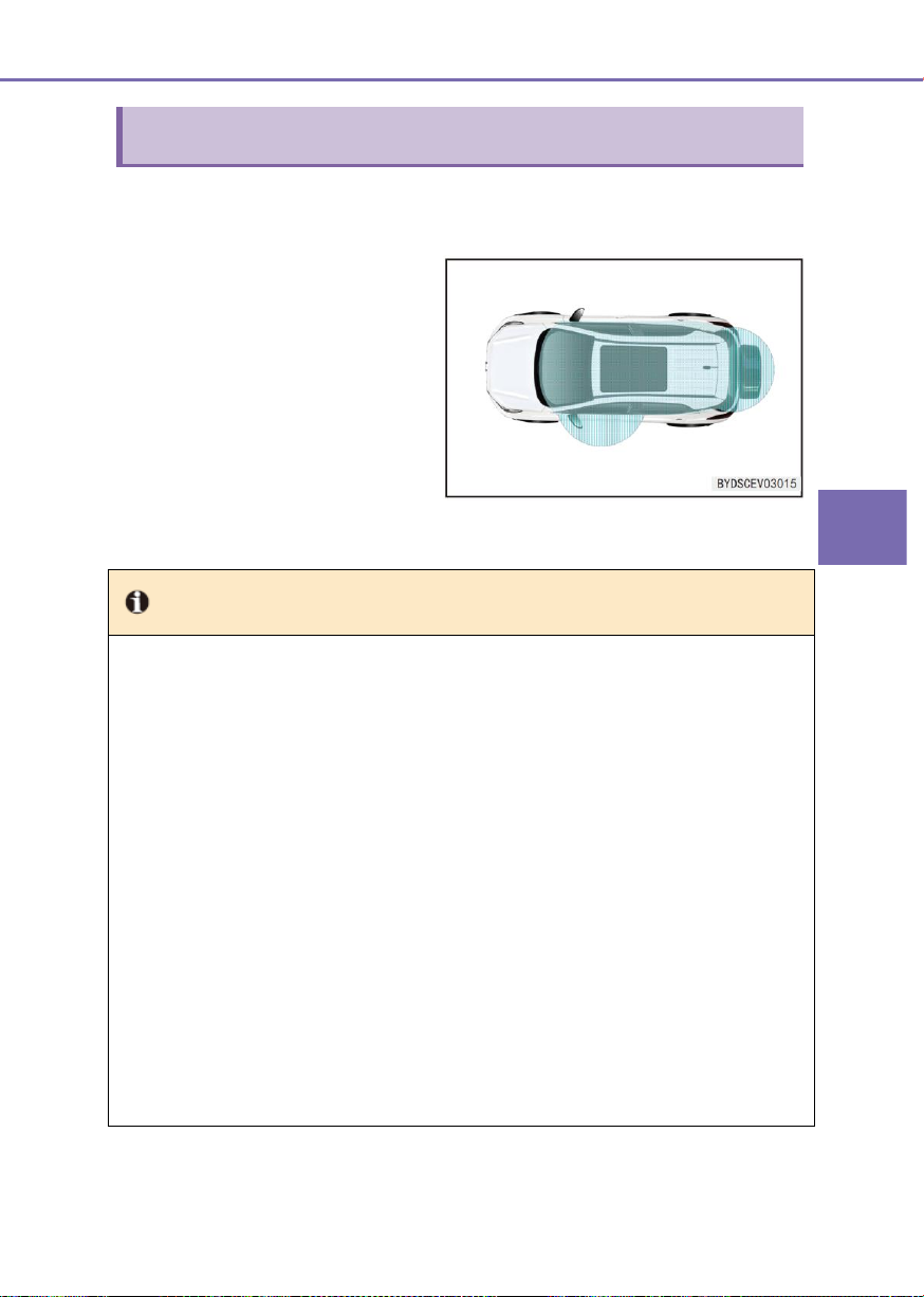
3
Controller Operations
3-1 Key and door
63
Active area
■ Enter the function activate area –
within about 1m from the front
outside door handle micro
switches. If the electronic smart key
is too close to the door handle or
window, the access function may
not be activated.
Tip
The smart access and start system may not be operated normally in the following cases:
● When there is any facility to release strong electromagnetic wave, such as TV tower,
power station, and broadcasting station.
● When the smart key is carried with the communication device, such as a two-way radio
communication device or a mobile phone.
● When the smart key is in contact with or covered by a metal object.
● When the micro switch is operated quickly.
● When the smart key is close to the door handle.
● When the wireless remote control function on another nearby car is operated.
● When the battery power is exhausted.
● The smart key is close to a high voltage device or a device that generates a noise.
● When the smart key is carried along with another car`s smart access and start system
key or any other device that generates a radio wave.
● Even in the active area, the smart key may not be operated normally due to the position
of the smart key or the shape of the body.
Only when the registered smart key is in the active area, the smart access function and the
one-key start function can be used.
Page 64

64
3-1 Key and door
■ If the smart access and start system is not operated normally and cannot be placed in
the car, the driver door can be unlocked and locked with the mechanical key in the
electronic smart key.
■ When the smart key for another car is close to the smart key of the car, the door
unlocking time may be longer that the normal time.
■ The exterior rearview mirror footlights and rear indoor lights will be turned on/off
automatically based on the presence of the smart key, door unlocking/locking
condition, door opening/closing status, and power supply positions.
If the smart key battery is exhausted
■ If the electronic smart key indicator does not flash and the car cannot be started with
the start function, the battery may be exhausted and should be replaced as soon as
possible.
■ When the car is started when the electronic smart key battery is low-voltage, must
place the smart key close to the start button and press the start button.
Save the battery power
Even if the car is not started, the key can be communicated with the car. Therefore, do not
leave the key near the car (within the range of 2m).
■ The smart access and start system can be reactivated with one of the following
methods:
● The driver carrying the electronic smart key presses the micro switch on the front
outer door handle.
● Perform the wireless remote operation.
■ If the smart key receives strong electromagnetic waves for a long time, the battery
power will be exhausted. The electronic smart key must be at least 1m away from the
following devices:
● TV
● PC
● Wireless phone charger
● Lamp stand
● Fluorescent table lamp
■ If the smart access and start system is not operated normally due to any fault, it is
recommended to bring all smart keys to BYD Auto Authorized Service Station for
repair.
Page 65
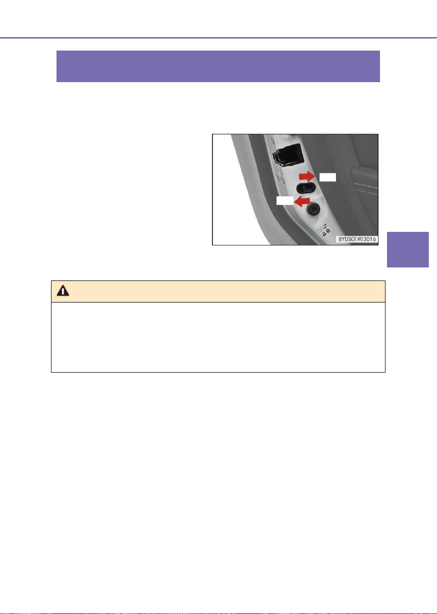
3
Controller Operations
3-1 Key and door
65
Child lock
■ When the latch is in “Lock” position,
the door cannot be opened in the
car. The door can be opened with
the outside door handle.
Note
● Before driving, especially when there is a child in the car, ensure that the doors are
closed and the child lock is locked.
● Proper use of the seatbelts and locking of the door can prevent the driver and
passengers from being thrown out of the car in case of an accident. It also can prevent
the doors from accidental opening.
Unlock
Lock
■ To prevent the child sitting in the rear seat from inadvertently opening the rear door,
the car is equipped with a child lock, and the left and rear right doors are equipped with
door child lock latches.
Page 66

66
3-2 Seat
Front seat adjustment
Warning
● Do not drive the car until all passengers are seated properly.
● Do not sit on the folded seat backrest, in the luggage compartment or on the
luggage. Otherwise, In case of an emergency brake or a collision, any passenger
who is not seated correctly in the seat or does not wear the seatbelt normally may
be seriously injured.
● Do not allow the passenger to stand up or move between the seats during driving
process. Otherwise, the passenger may be seriously injured in case of an
emergency braking or a collision.
Tip
● The driver seat cannot be adjusted during driving process, so as to prevent the lose
control of the car from its uncontrollable movement.
● When the seat is adjusted, it cannot hit any passenger or luggage.
● After the front and rear position of the seat is adjusted manually, must ensure that
the seat is locked by moving it back and forth.
● After the seat backrest is adjusted, must lean back on the body to confirm that the
seat backrest is locked.
● Do not place any object under the seat; otherwise, it may affect the seat lock
mechanism or accidentally push the seat position adjustment lever upward, resulting
in the sudden seat movement and the lose control of the car.
● When the seat is adjusted, do not put the hand under the seat or near the operating
parts; otherwise the hand or fingers may be crushed.
3-2 Seat
During driving process, all passengers in the car must maintain the seat backrest upward,
their backs against the seat backrests and wear the seatbelts properly.
Notes on seat adjustment:
Adjust the driver's seat so that the foot pedal, the steering wheel and the dashboard
controller are all within the easy control range of the driver.
Page 67
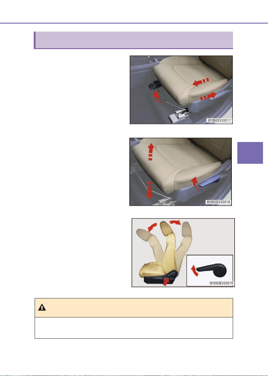
3
Controller Operations
3-2 Seat
67
Seat adjustment
1. Front and rear adjustment of the
seat
■ Hold the middle of the adjustment
handle and pull it up, then slide the
seat back and forth to the desired
position with a slight body pressure,
and release the adjustment handle.
■ After the front and rear position of
the seat is adjusted, slide the seat
back and forth to ensure that the
slide lock sound is sound and the
seat is locked in position.
2. Height adjustment mechanism
handle
Pull up the height adjustment
mechanism handle to adjust the seat to
a comfortable height. (Note: The front
passenger seat is not equipped with the
height adjustment mechanism).
■ Pull the height adjustment
mechanism handle up is to raise
the seat, and press it down to lower
the seat.
3. Backrest adjustment handle
Pull the handle up, tilt the seat backrest
forward or backward to adjust it to the
desired position and release the handle.
Note
● When the seat cushion depth is measured, the front and rear position of the seat is
the limit positions of the slide rail, and the backrest has the design angle of 23°.
Page 68
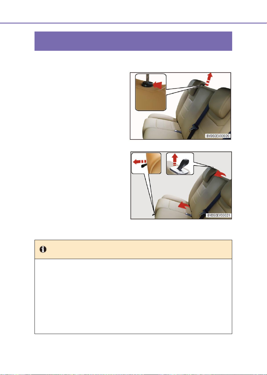
68
3-2 Seat
Rear seat folding
1. Remove the headrest in the middle
of the rear seat (if fitted) and adjust
the seat headrests on both sides of
the rear seats to the lowest position.
2. Pull up the unlocking webbing on
the rear right seat cushion and flip
the seat cushion forward.
3. Pull up on the unlocking webbing
on the back seat backrest and fold
the backrest forward.
The left/rear right seats should be folded
in the same way. The seats should be
restored in the reverse of the above
steps.
Tip
● Before folding the backrest, must remove the middle headrest and flip the seat
cushion.
● When the seat cushion is restored, must press it down first to ensure that the seat
cushion is locked in place.
● When the rear seats are folded and restored, please gently handle the seat backrest
and seat cushion to avoid damage to the seatbelts on the rear seats and backrests
or causing any fault.
● When the seats are restored, must place the seatbelts on both sides on the backrest
and place the seatbelt buckles into the grooves on the seat cushions.
Page 69
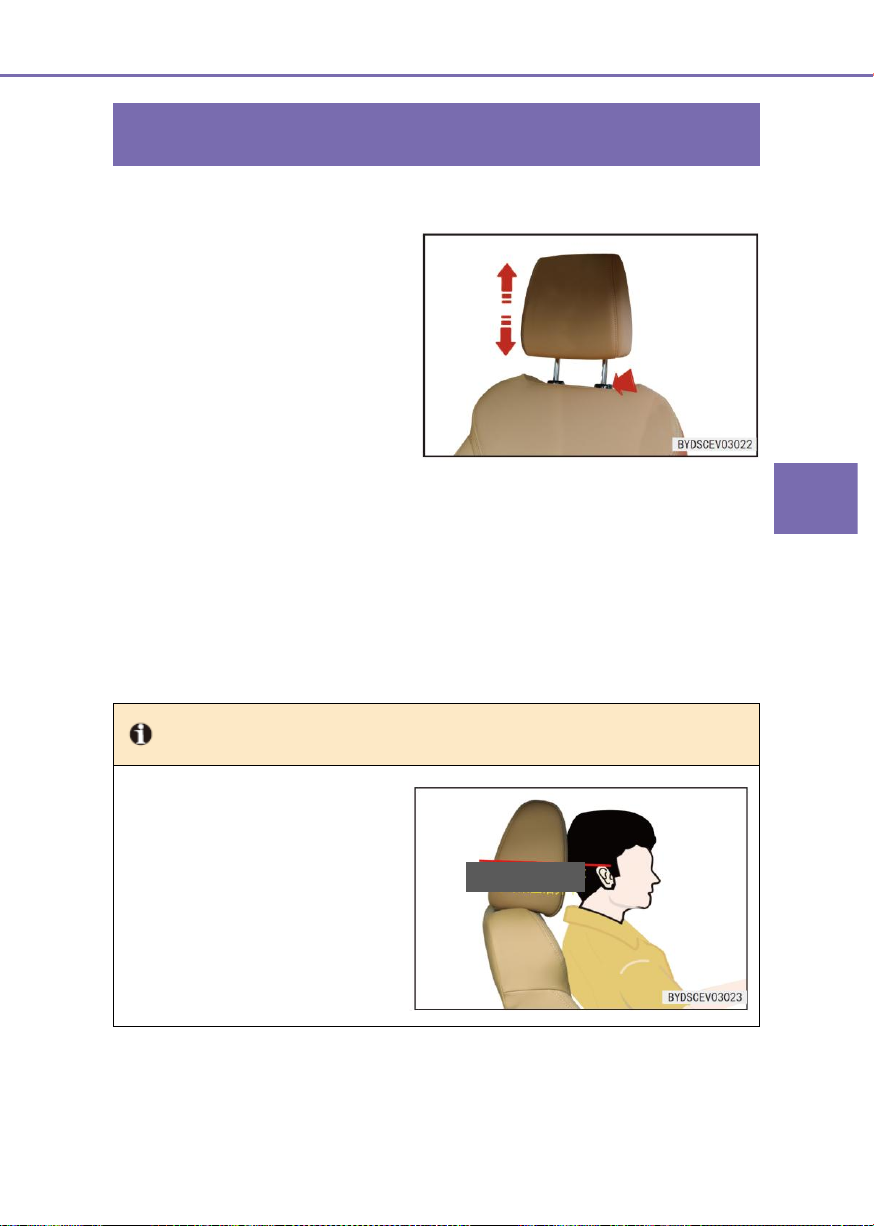
3
Controller Operations
3-2 Seat
69
Headrest
Pull up the headrest
Pull the headrest up to the appropriate
position along the headrest bar and
release it when a lock sound is heard.
Lower the headrest
Press and hold the headrest height
adjustment button to lower the headrest
to the appropriate position, release the
button, pull up the headrest a small
amount and release it when a lock
sound is heard.
Tip
● The headrests are used to avoid
the neck and head injuries of the
driver and the passengers.
When the center of the headrest
is adjusted to the head position,
it can provide maximum
protection. For a tall passenger,
the position of the headrest
should be adjusted as high as
possible.
To ensure that the soft part in the
middle of the headrest is flush
with the upper edge of the ear.
Remove the headrest
Press and hold the headrest height adjustment button, remove the headrest, and release
the button.
Install the headrest
Insert the headrest link into the bushing, press the headrest height adjustment button to
lower the headrest to the appropriate position, release the button, pull up the headrest a
small amount and release it after a lock sound is heard.
Page 70
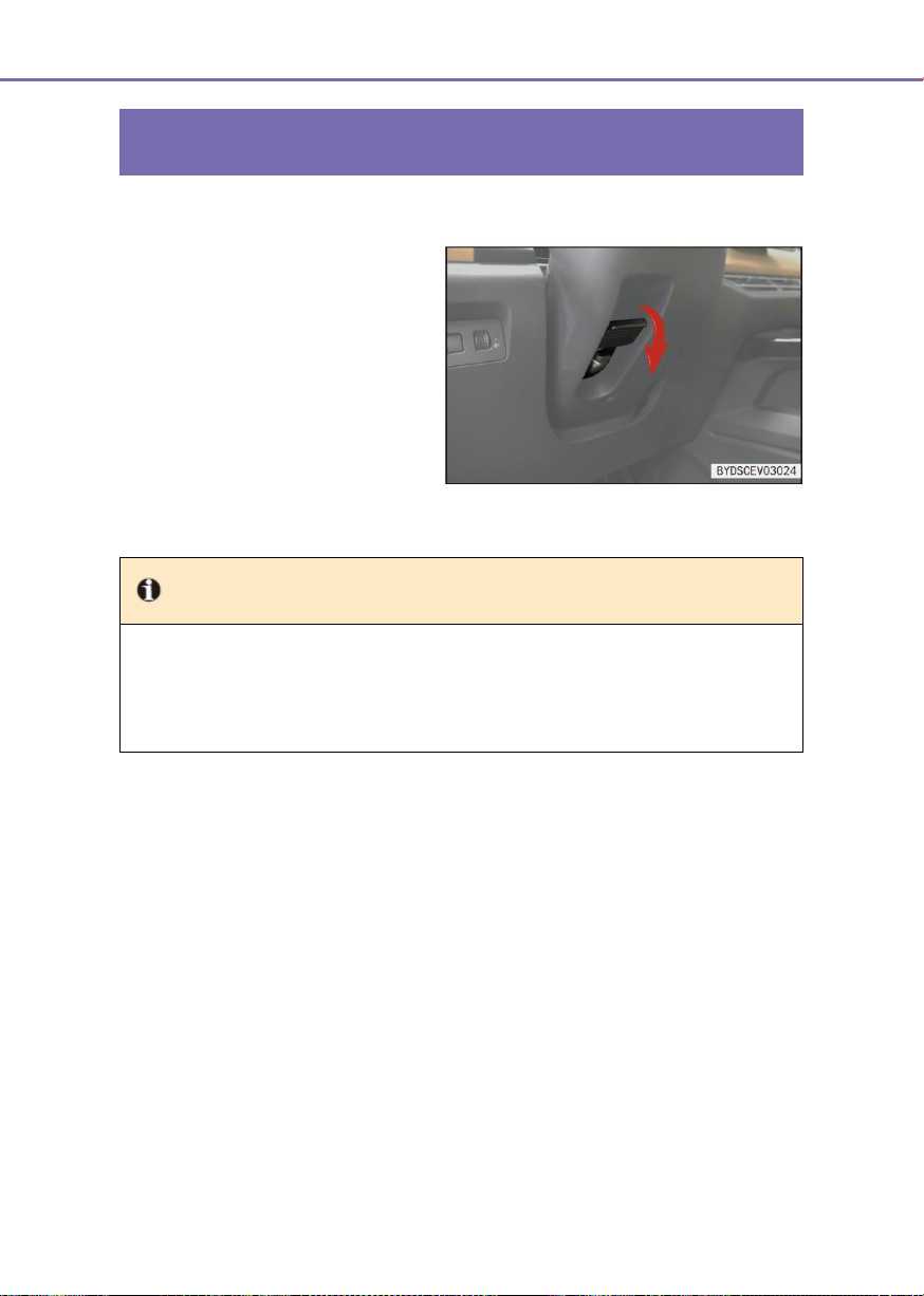
70
3-3 Steering wheel
Steering wheel adjustment
■ To adjust the angle of the steering
wheel, hold the steering wheel and
perform the following operations:
● Press the steering wheel
adjustment handle down to tilt
the steering wheel to the
desired angle and return the
handle to its original position.
Tip
● Do not adjust the steering wheel during driving process; otherwise the car may be
misoperated, resulting in an accident.
● After the steering wheel is adjusted, move it up and down to confirm that it is
securely locked.
3-3 Steering wheel
Page 71
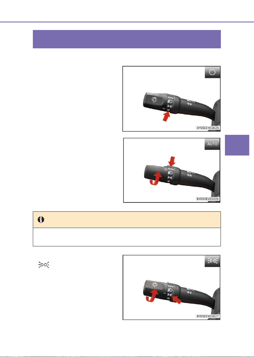
3
Controller Operations
3-4 Switch
71
Light switch
When the light knob is turned to “○”
position, all lights will be turned off.
When the light knob is turned to “AUTO”
position (if fitted), the low beam
headlights and small lights will be turned
on/off automatically based on the
lighting intensity sensed with the lighting
intensity sensor.
Tip
● The lighting intensity sensor is located at the top of the dashboard; do not cover it or
splash any liquid on it.
When the light knob is turned to
“ ” position, the small lights
(including the front position lights, rear
position lights, rear license plate light,
instrument backlight, small light
indicator and some backlights, and etc.)
will be turned on.
3-4 Switch
Configuration 1
Page 72
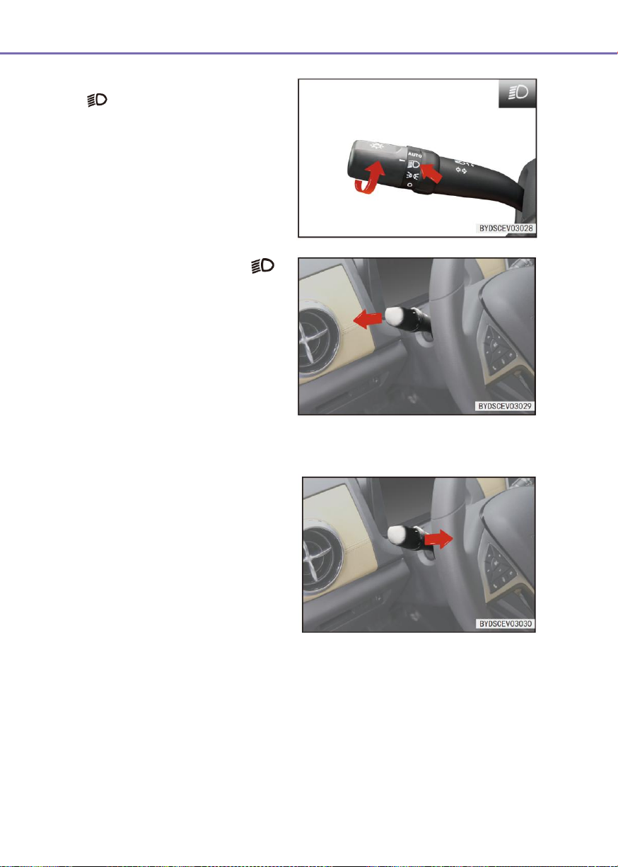
72
3-4 Switch
When the light knob is turned to the
“ ” position, the low beam lights will
be turned on.
■ With the lighting knob at “ ”
position, push forward (away from
the steering wheel) the lighting
combination switch handle from
initial position and release. In such
case, the handle returns by self to
initial position, the high beam turns
on, and the high beam indicator
lamp on the instrument also turns
on.
■ Operating the lighting handle
“forward/backward” can turn off the
low beam or exit the “OK” position
and turn off the high beam.
Overtaking light
■ When the light handle on the
combination switch is pulled back
from the original position (close to
the steering wheel), the overtaking
light will be turned on; when it is
released, the light handle on the
combination switch will be reset
automatically and the overtaking
light will be turned off. Pull
backward (Towards the steering
wheel) and hold the lighting handle.
The overtaking lamp keeps on once
this handle is pulled backward and
held.
■ When the lighting knob is at “○”, the overtaking lamp can also be turned on. Releasing
or exiting the “OK” will turn off the overtaking lamp.
Page 73
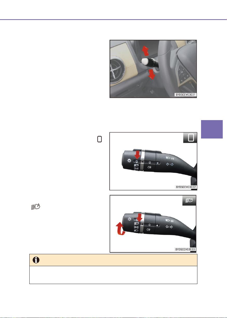
3
Controller Operations
3-4 Switch
73
■ When the light handle on the
combination switch is push upward,
the right turn signal and the turn
indicator on the dashboard will flash
at the same time.
■ When the light handle on the
combination switch is pulled down,
the left turn signal and the turn
indicator on the dashboard will flash
at the same time.
When the light knob is turned to “ ”
position, all lights will be turned off.
When the lighting knob is rotated to
“ “ position (if fitted), the low beam
and the marker lamp will be turned on or
off automatically based on the lighting
intensity detected by the lighting
intensity sensor.
Tip
The lighting intensity sensor is located at the top of the dashboard; do not cover it or
splash any liquid on it.
Turn signal
When it’s pushed to the topmost or bottommost position, the turn signal lamp keeps
flashing, even if it’s released. The turn signal lamp turns off automatically after the
cornering is completed.
Configuration 2
Page 74
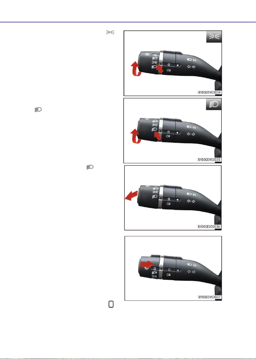
74
3-4 Switch
When the light knob is turned to “ ”
position, the small lights (including the
front position lights, rear position lights,
rear license plate light, instrument
backlight, small light indicator and some
backlights, and etc.) will be turned on.
When the light knob is turned to the
“ ” position, the low beam lights will
be turned on.
With the lighting knob at “ “ position,
push forward (away from the steering
wheel) the lighting combination switch
handle from initial position and release.
In such case, the handle returns by self
to initial position, the high beam turns
on, and the high beam indicator lamp on
the instrument also turns on. Operating
the lighting handle “forward/backward”
can turn off the low beam or exit the
“OK” position and turn off the high
beam.
Overtaking light
■
When the light handle on the
combination switch is pulled back
from the original position (close to
the steering wheel), the overtaking
light will be turned on; when it is
released, the light handle on the
combination switch will be reset
automatically and the overtaking
light will be turned off.
■
When the lighting knob is at “ ”,
the overtaking lamp can also be
turned on.
Page 75
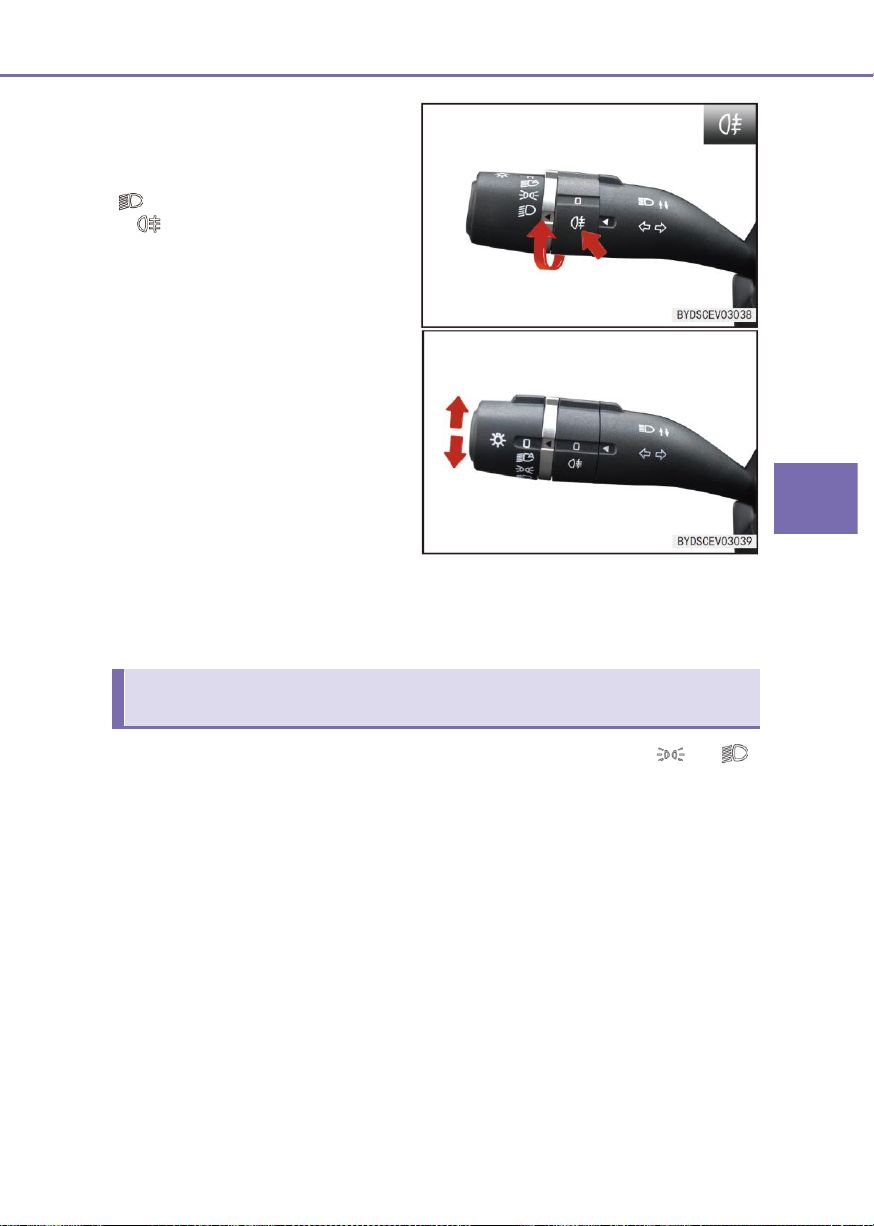
3
Controller Operations
3-4 Switch
75
Rear fog lamp
The rear fog lamp turns on when the
end knob of lighting switch is rotated to
“ ” and the fog lamp knob is rotated
to “ ”. Turning off the marker lamp or
rear fog lamp switch or exiting the “OK”
position can turn off the rear fog lamp.
Turn signal
■ When the light handle on the
combination switch is push upward,
the right turn signal and the turn
indicator on the dashboard will
flash at the same time.
■ When the light handle on the
combination switch is pulled down,
the left turn signal and the turn
indicator on the dashboard will
flash at the same time.
Auto-off function(The whole vehicle is in a non-theft state)
When it’s pushed to the topmost or bottommost position, the turn signal lamp keeps
flashing, even if it’s released. The turn signal lamp turns off automatically after the
cornering is completed.
■ Auto-off function activating conditions: When the headlight switch is in “ ” or “ ”
position and the power supply is switched from “On” to “Stop” status, the function will
be activated.
■ After the auto-off function is activated, if the two front doors are closed, after 11s, the
headlights, and small lights will be turned on with auto-off function automatically.
■ After the auto-off function is activated, if any of the two front doors is opened, after
10min, the headlights and small lights will be turned off with the auto -off function
automatically.
■ After the lights are turned off automatically, if the light position status are changed, the
lights will be turned on under the new status; if the auto-off conditions are still met at
the time, the auto-off function will be activated again.
■ After the lights are turned off automatically and any of the two front doors is opened,
the lights will be turned on automatically.
■ At end of auto-off function: After the power switch is turned on, the auto-off function will
be completed and the light knob can be operated normally.
Page 76

76
3-4 Switch
Follow me home function (if fitted)
■ After the lights are turned off with auto-off function and the anti-theft status is entered,
if the anti-theft status is released, and the lights will be turned on automatically again. If
the two front doors are not open, the lights will be turned off with auto-off function after
10s. If any of the two front doors is opened, the lights will be turned off with auto-off
function after 10min.
■ Follow me home light:
● With the lighting combination switch at “ ”, “ ”, or “ ” position, the
power switch at “OFF”, and the Follow Me Home set at “ON”, when the vehicle is
locked remotely or by micro-switch, the corresponding lamp will keep on for a
period (0~60s, depending on the specific setting). The factory default setting is
10s.
■ Off-home light:
● With the lighting combination switch at “ ”, “ ”, or “ ” position, the
vehicle under locked status, and the Follow Me Home set at “ON”, when the
vehicle is unlocked remotely or by micro-switch, the corresponding lamp will keep
on for a period (0~60s, depending on the specific setting). The factory default
setting is 10s.
Page 77
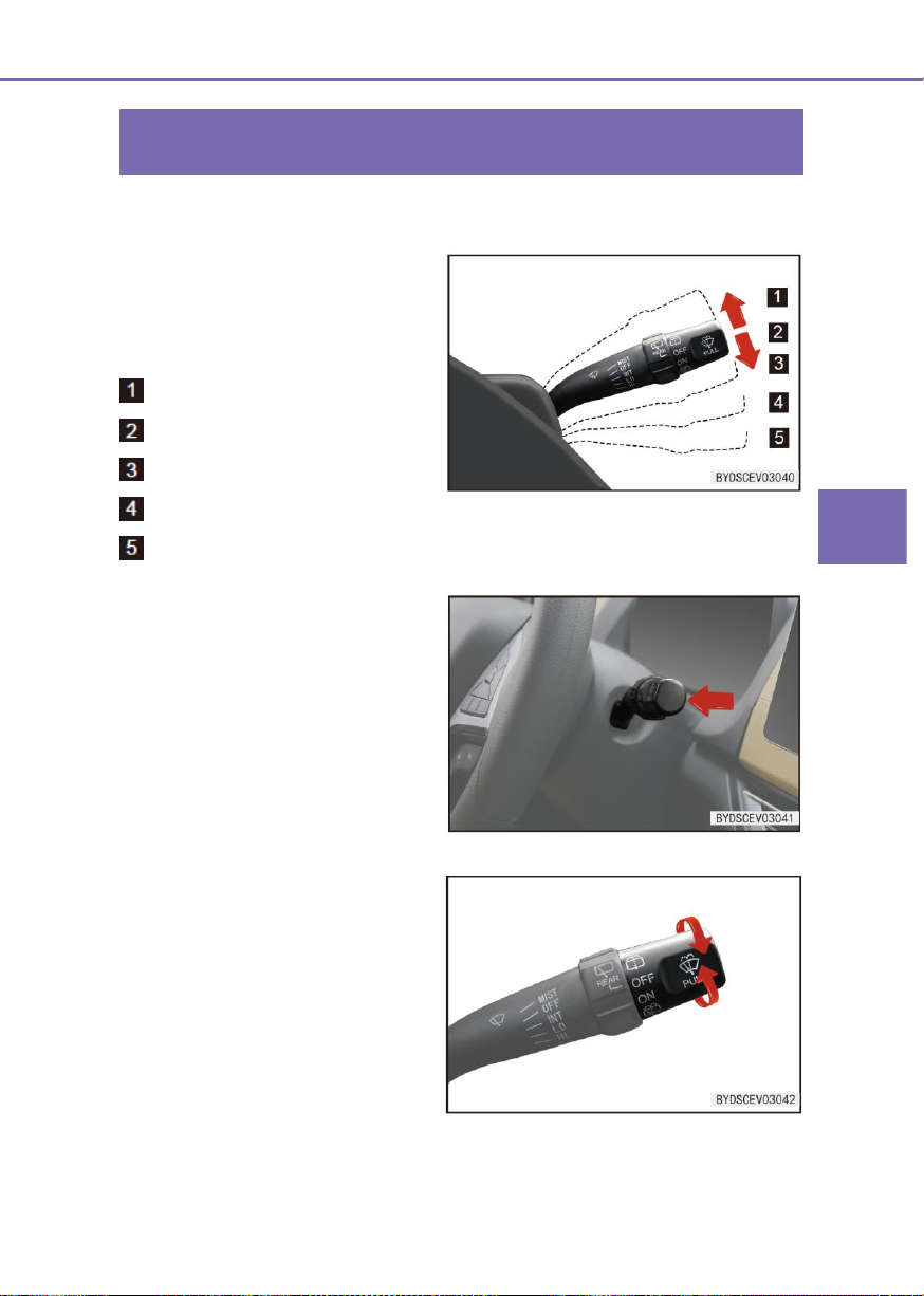
3
Controller Operations
3-4 Switch
77
Wiper switch
Front and rear windshield wipers
The control lever is used to control the
front and rear windshield wipers and
scrubbers. The front windshield wiper is
controlled with five gears;
MIST: Jogging mode
OFF: Stop mode
INT: Intermittent mode
LO: Low speed mode
HI: High speed mode
Front windshield scrubber
■ To clean the front windscreen, pull
backward (Towards the steering
wheel) the wiper control handle so
that the scrubber sprays washing
fluid and meanwhile the wiper runs.
■ Upon release of the control handle,
the scrubber stops the spraying of
washing fluid and the wiper
continues to wipe for 2~3 cycles
and then stops.
Rear windshield wiper and scrubber
(if fitted)
■ If turning the switch knob to “ON”
position, the rear windshield wiper
will be started; if turning the switch
knob to “OFF” position, the wiper
will stop.
Configuration 1
Page 78
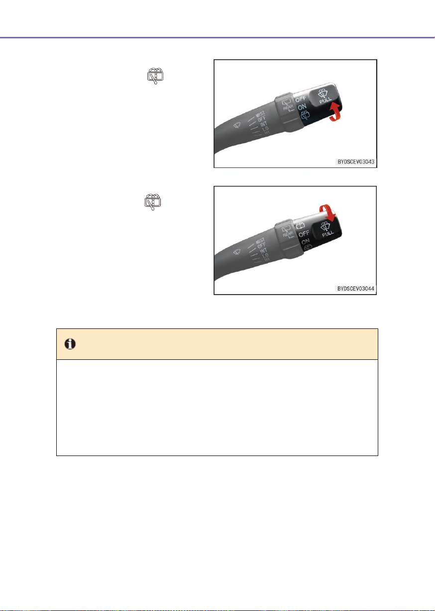
78
3-4 Switch
■ If the switch knob is turned up to the
rear wiper position “ ”, the rear
windshield wiper and scrubber will
be operated simultaneously, and the
working time is related to the holding
time of the switch knob at the
position.
■ Rotate downward the switch knob to
rear wiper position to run both
rear windscreen wiper and scrubber
simultaneously. Upon release, this
switch returns automatically and
both rear windscreen wiper and
scrubber stop working
simultaneously.
Tip
● Regularly inspect the wiper blade and remove the dirt attached on the wiper blade,
to prevent dry operation.
● If the wiper is turned on just at beginning of rain, because the rainwater is mixed with
sand and dust, not only the sand and dust on the windshield cannot be cleaned, but
a blurred vision may be formed instantly, which may affect the safety of driving.
● Please use the glass cleaner. The water or any other detergent may cause damage
to the scrubber motor.
Page 79
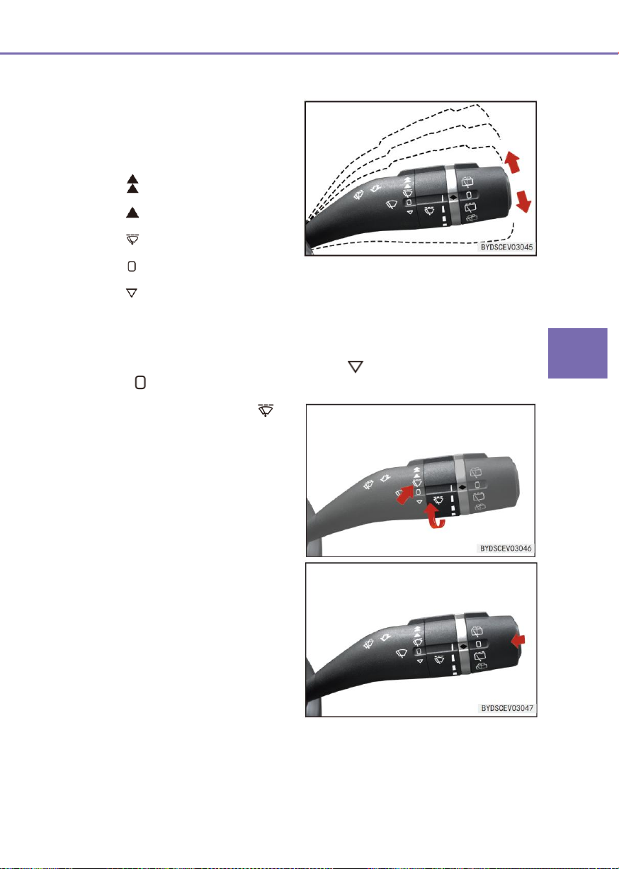
3
Controller Operations
3-4 Switch
79
■ The control lever is used to control
the windshield wiper and scrubber.
The lever is controlled with five
gears:
:
High speed mode
:
Low speed mode
:
Intermittent mode
:
Stop mode
:
Jogging mode
■ Under the intermittent mode “ ”,
rotate the intermittent knob on the
wiper switch to prolong the wiping
interval along the narrowing of the
rainfall indicator bar.
Front windshield scrubber
■ To clean the front windscreen, pull
backward (Towards the steering
wheel) the wiper control handle so
that the scrubber sprays washing
fluid and meanwhile the wiper runs.
■ When the control handle is released
or the continuous running time
exceeds 10s, the scrubber stops
spraying and the wiper wipes for 1~2
cycles and then stops. After an
approximately 5s interval, the wiper
wipes once further to remove the
residual water drops from the
windscreen.
Configuration 2
■ To select a level, pull up or push down the control handle.
■ The wiper wipes continuously at low speed and high speed positions.
■ To run the wiper under one-time wiping mode “ ”, push down the control handle
from “ ” to run the wiper at low speed, till the control handle is released.
Page 80
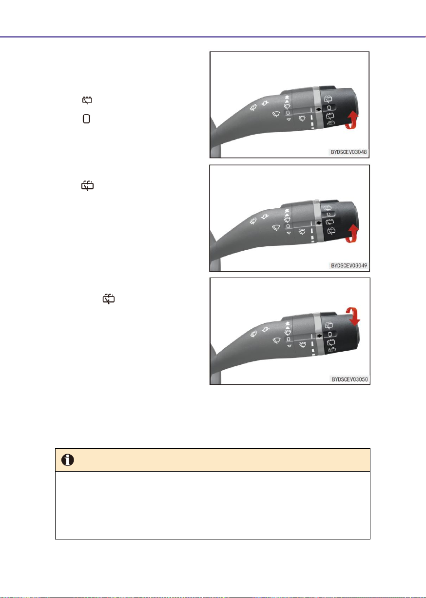
80
3-4 Switch
Rear windshield wiper and
scrubber (if fitted)
■ Rotate the end knob of wiper switch
to position to turn on the rear
windscreen wiper. Rotate the knob
to “ ” or open the back door to stop
both wiper and scrubber.
■ Rotate the end knob of wiper switch
to position to turn on both rear
windscreen wiper and scrubber.
■ Rotate the switch knob to rear wiper
position and release. After the
spraying of washing fluid, the wiper
wipes for 1~2 cycles and then stops.
After an approximately 5s interval,
the wiper wipes once further to
remove the residual water drops
from the windscreen.
Rear wiper and back door
linkage function (if fitted)
Tip
● Do not run the scrubber continuously for >10s or operate the scrubber when the
washing fluid reservoir is empty, otherwise it will probably result in overheated
damage of motor.
● Regularly inspect the wiper blade and remove the dirt attached on the wiper blade, to
prevent dry operation.
■ With the vehicle power switch at “OK”, when the back door is opened, the rear
wiper/scrubber is not operational. While the rear wiper/scrubber is working, the
wiper/scrubber stops working if the back door is opened and resumes working in 5s
after the back door is closed. While the front wiper is working, the rear wiper will work
automatically if the gear R is engaged.
Page 81
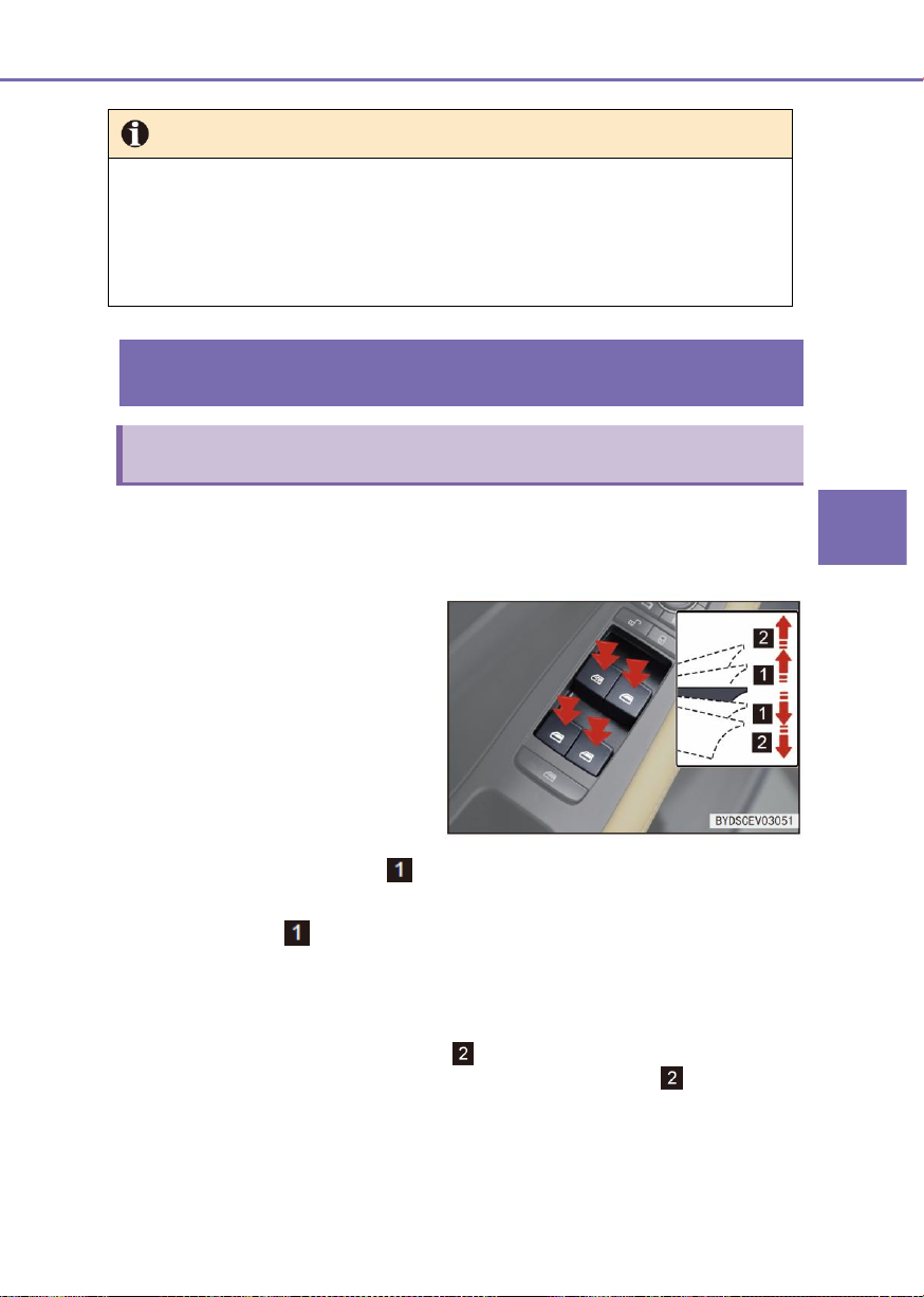
3
Controller Operations
3-4 Switch
81
Tip (continued)
● If the wiper is turned on just at beginning of rain, because the rainwater is mixed with
sand and dust, not only the sand and dust on the windshield cannot be cleaned, but
a blurred vision may be formed instantly, which may affect the safety of driving.
● Please use the glass cleaner. The water or any other detergent may cause damage
to the scrubber motor.
Front left door switch assembly
Power window switch
Driver window control switch
There are four buttons on the driver
window control switch, used to operate
the four doors glasses separately.
Manual operation:
When the power supply is in “OK” position, the operations of the door glass can be
controlled with the side window control switch. When the power switch is in “OFF” position,
the power window will not be operated.
■ There are 2 positions on the window control switch with anti-pinch function. If pressing
the window control switch to st position and hold it (or if directly pressing the
window control switch and hold it on the car without the anti-pinch function), the
window will be lowered; if releasing it, the window will stop; if pulling up the window
control switch to st position and hold it (or if directly pulling up the window control
switch and hold it on the car without the anti-pinch function), the window will be lifted; if
releasing it, the window will stop.
One-button operation (if fitted)
■ If pressing the window switch button to nd position and releasing it, the window will
drop automatically; if pulling up the window control switch button to nd position and
release it, the window will be lifted automatically.
● The window with anti-pinch function has automatic operation function, and the
window without anti-pinch function has not automatic operation function. No
matter the anti-pinch function is fitted or not, the driver window incorporates the
Page 82
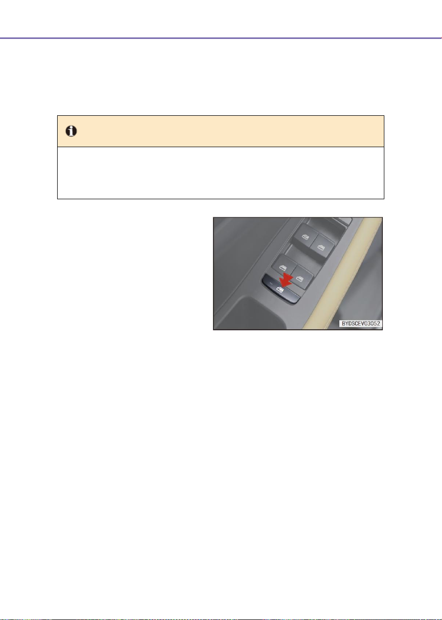
82
3-4 Switch
Tip
● Do not intentionally pinch a part of your body to test the anti-pinch function.
● If an object is pinched when the window is about to be closed completely, the
anti-pinch function may be invalid.
Window lock button
■ Press the window locking button.
The indicator lamp turns on and the
driver and front passenger can lift
and lower the glass of
corresponding window, but the rear
passengers can’t control the glass
lifting and lowering of the
corresponding window.
■ Press the window locking button
again. The indicator lamp turns off
and all window control switches
restore operational.
one-touch lowering function.
Anti-pinch function (if fitted)
If a person or object is pinched during the door glass operation, the glass will stop and drop
to a certain distance automatically.
Delay function (if fitted):
■ After the power switch is turned off, if the doors are not opened, they can be operated
after a delay of 10min.
■ After the power switch is turned off, if any front door is opened, the window glasses
cannot be operated with the four-door control function.
Intelligent window control function (if fitted)
■ When this function is turned on by instrument or multimedia setting (see dashboard
or multimedia setting operation): If pressing and holding “Unlock” button on the remote
control, the glass will drop automatically; if pressing and holding “Lock” button on the
remote control, the glass will be lifted automatically. Release the button during the
motion of glass to stop the motion.
■ When this function is turned on by instrument or multimedia setting (see dashboard
or multimedia setting operation): if the driver carrying the smart key presses and holds
“Unlock” button on the front door micro switch, the glass will drop automatically, if
pressing and holding “Lock” button on the front door micro switch, the glass will be
lifted automatically. Release the button during the motion of glass to stop the motion.
Page 83
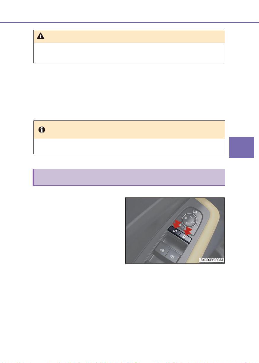
3
Controller Operations
3-4 Switch
83
Warning
● When closing the power window, do not put your hand on the window glass. To
avoid pinching your hand or fingers and causing extremely serious injuries.
Tip
● When leaving the car, must carry the smart key with you.
Central control door lock switch
■ If pressing “Central Lock” button,
the four door locks will be locked at
the same time, and the locking
indicator (red) will be turned on.
■ If pressing “Central Unlock” button,
the four door locks will be unlocked
at the same time, and the locking
indicator (red) will be turned off.
■ When the driving speed exceeds
about 20km/h, all doors will be
locked automatically.
Window auto-lifting function and anti-pinch function fault (if fitted)
■ If the automatic lifting or anti-pinch function of the window fails, restore this function by
following procedure:
● Continuously pull the front left window switch to lift the glass to the top.
● Release the switch and pull the front left window switch again and hold it 400ms;
The auto-lifting and anti-pinch function will be restored.
■ After the power switch is turned off, all doors will be unlocked automatically.
■ In case of a strong collision, all doors will be unlocked automatically. Whether all doors
are unlocked automatically depends on the specific collision strength and the type of
accident.
Page 84
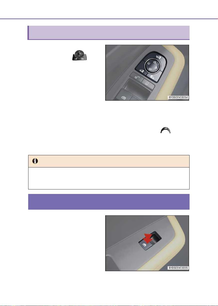
84
3-4 Switch
Exterior rearview mirror adjustment switch
Exterior rearview mirror
adjustment switch
■ If the left exterior power rearview
mirror adjustment switch is
pressed, the left exterior rearview
mirror will be selected.
■ If the right exterior power rearview
mirror adjustment switch is
pressed, the right exterior rearview
mirror will be selected.
Tip
● If the rearview mirror is frozen, do not operate the controller or clean the surface of
the rearview mirror; the ice on the mirror surface should be removed with a spray
deicer.
Passenger window control switch
■ When the power supply is in “OK”
position, the front right and rear
door glass can be controlled with
the front right and rear door window
control switches respectively.
■ The exterior rearview mirror lens can be adjusted in four directions, namely “Up”,
“Down”, “Left” and “Right”, corresponding to the up, down, left and right actions on the
switch.
Exterior power rearview mirror folding switch (if fitted)
If pressing the folding button, the left and right exterior rearview mirrors will be folded at the
same time; if pressing the folding button again, the left and right exterior rearview mirrors
will be returned to the original position before folding operation.
Page 85
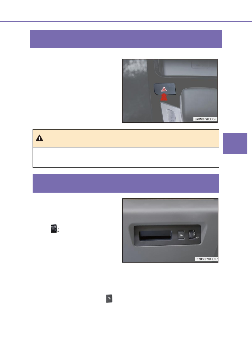
3
Controller Operations
3-4 Switch
85
Emergency warning indicator switch
■ Press the hazard warning lamp
switch to synchronously flash the
turn signal indicator lamp on the
instrument and the hazard warning
lamp switch. Press it again to stop
the flashing.
Warning
● Turn on the emergency warning indicator to remind other pedestrians and cars to
avoid any risk.
Lighting adjustment switch group
The lighting adjustment switch group is
composed of headlamp adjustment
switch.
Headlamp adjustment
switch
■ This switch is used to adjust the
vertical illumination angle of the
headlamp. This switch is
operational after the low beam is
turned on.
■ The illumination height of the headlamp is the maximum when the headlamp
adjustment switch is at 0 position and is the minimum when the headlamp adjustment
switch is at 5 position. Depending on the driver’s need, adjust the switch to any of 0~5
positions to change the illumination height of the headlamp.
Mileage adjustment switch
■ Press the mileage switch repeatedly to circulate the mileage interfaces on the
instrument. Press and hold this button to reset mileage I or II.
Page 86
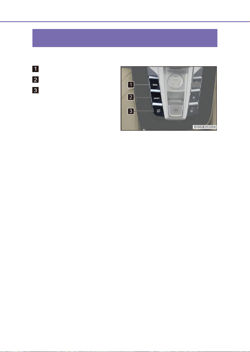
86
3-4 Switch
Mode switch group
Economy mode button
Sport mode button
Snow mode button
■ The Economy/Sport/Snow mode
button controls the mode
switchover of vehicle.
Start
Stop
Automatic
On
Off
Front
Page 87
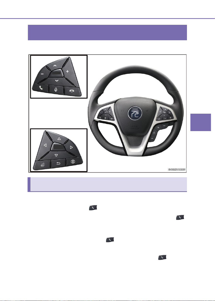
3
Controller Operations
3-4 Switch
87
Steering wheel switch group
Left switches
Mode
OK
Configuration 1
Definitions of Bluetooth function buttons:
Dialup/Answer button (if fitted):
■ When the system is in any interface not related to the Bluetooth, press the “ ”
button on the steering wheel to switch over to phone selection main interface (If no
Bluetooth device is paired) or dialup main interface (If a Bluetooth device is already
paired).
■ In event of an incoming call, press the “ ” button on the steering wheel to answer
the call.
■ After inputting a telephone number in the dialup interface or selecting a record from
Recent Calls or Contacts or in the Speed Dialup interface, press the “ ” button on
the steering wheel to dial up.
Page 88

88
3-4 Switch
■ When a Bluetooth device is already paired and no phone number is inputted in the
dialup main interface, press the “ ” button on the steering wheel to directly switch
over to All Calls interface in Recent Calls interface and press the “ ” button on the
steering wheel again to automatically dial up the first record in the All Calls interface.
End Call button (if fitted)
■ During a phone call, press the “ ” button on the steering wheel to end the call.
■ In any interface related to Bluetooth, press the “ ” button on the steering wheel to
exit the Bluetooth interface and return to the previous non-Bluetooth interface.
Volume “+” /Volume “-” button
■ Use the Volume “+” and “-“ buttons on the steering wheel to adjust the volume of
incoming call tone and phone call.
Up “∧” /Down “∨” button
■ In the Contacts, Recent Calls, or Speed Dialup interface, press the “∧/∨” buttons on
the steering wheel to switch over the call records in turn. (The switchover sequence of
speed dialup is 1-6-12-18-1.) (Reserved speed dialup records)
Multimedia function:
Voice button (if fitted):
■ Press the voice recognition switch to switch over the multimedia display screen to
voice recognition interface and realize the intelligent voice function. Press again to
re-input the voice command.
Volume “+” /Volume “-” button
■ Volume adjustment
Up “∧” button
■ In radio mode
● Press and hold: Automatically search for the previous strong signal station
(decrease the frequency)
● Press: Select the previous pre-stored station;
■ Under the USB/SD/Bluetooth music/third-party music APP mode: Play the previous
music (music number -1).
■ Bluetooth call Record, phone book interface, Press: Select the previous item.
Page 89

3
Controller Operations
3-4 Switch
89
Right switches
OK
Mode
Mode
Down “∨” button
■ In radio mode:
● Press and hold: automatically search for the next strong signal station (decrease
the frequency)
● Press: Select the next pre-stored radio station;
■ Under the USB/SD/Bluetooth music/third-party music APP mode: Play the next music
(music number -1).
■ Bluetooth call Record, phone book interface, Press: Select the previous item.
Press Mode button:
■ Select the mode among Radio → Music → Video → AUX → Bluetooth in sequence. If
the audio is turned off, press the button to boot the device and enter the
memory playback mode before the last turning off, and press and hold the button to
turn off the audio.
OK button
■ Under the menu interface, press the button to select the corresponding submenu
option in the menu;
■ Under the driving information interface, press and hold the button to clear some driving
■ Under the driving information interface, press the button to switch to the safe driving tip
■ Under the fault/tip information interface, press the button to switch to the driving
Up /Down button
■ Press Up button:
■ Press Down button:
information;
interface or the menu interface;
information display interface.
● Under instrument menu mode, select level-2/level-3 menu item in upward
direction.
● During reserved charging setting, reduce the hour/minute.
● Under instrument menu mode, select level-2/level-3 menu item in downward
direction.
● During reserved charging setting, increase the hour/minute.
Page 90

90
3-4 Switch
Left /Right button
■ Under instrument menu mode:
● Press button to switch leftward the level-1 menu and its submenu.
● Press button to switch rightward the level-1 menu and its submenu.
■ During reserved charging setting:
● Press button to switch leftward the hour and minute setting.
● Press button to switch rightward the hour and minute setting.
Return button
■ Under the non-menu mode of instrument, press the Return button to pop up
instrument menu.
■ Under the instrument menu mode, press Return button to return to upper level menu
or (If no upper level interface is available) exit the menu.
■ In the Bluetooth call interface, press to end call.
Customize button (if fitted)
■ If the Customize button is not defined, press or press and hold to enter the
Customization interface. The customization functions include “Take photograph by
traveling data recorder”, “Rotate central control display”, and “Lock video in traveling
data recorder”.
■ If the Customize button is already defined with certain function, press to activate this
function and press and hold to enter Customization interface. It can also re-customize
or cancel current customization.
Panoramic view button (if fitted)
■ The multimedia system enters into panoramic view mode to display the interface of
panoramic view + front view.
Right front view button (if fitted)
■ The multimedia system enters the panoramic view mode. In the reverse gear, the right
front view interface and the reversing camera interface are switched over with each
other.
Page 91
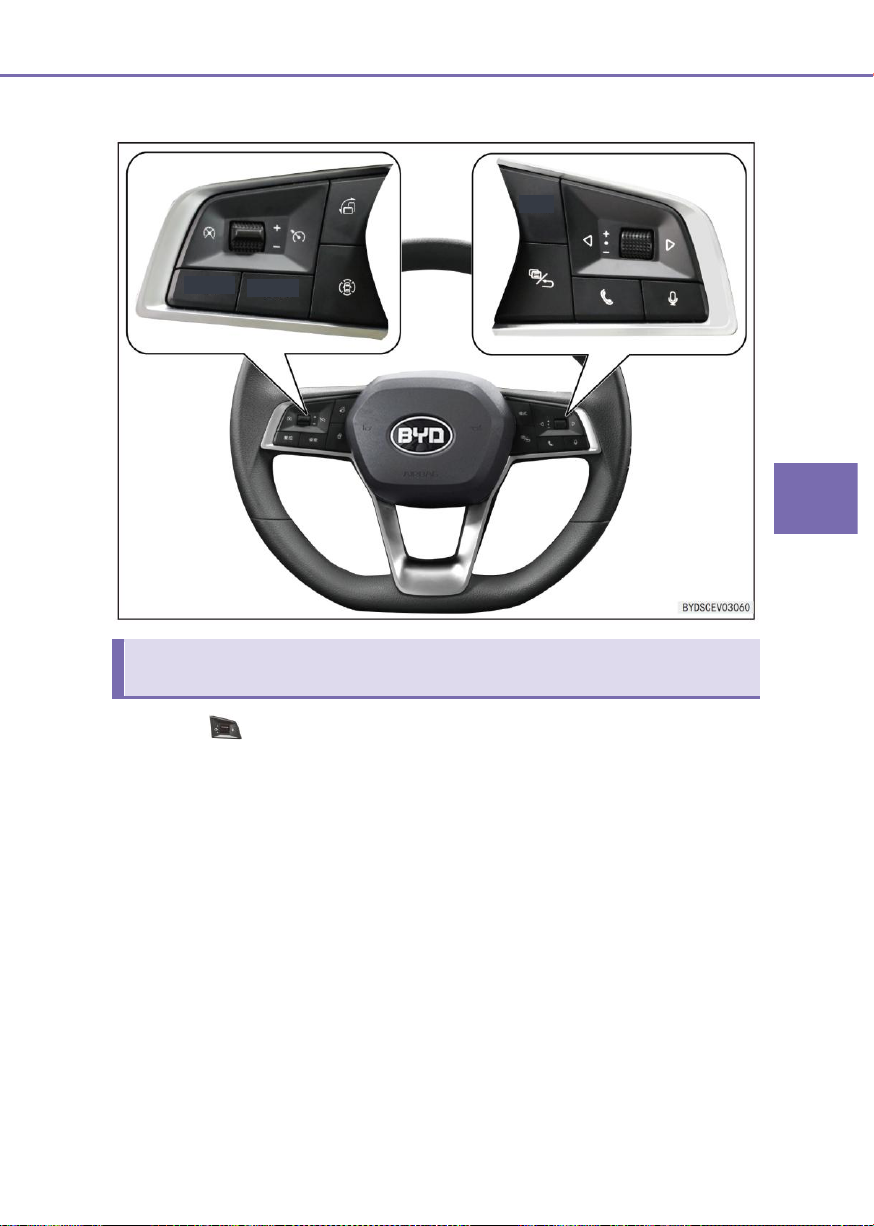
3
Controller Operations
3-4 Switch
91
Right switches
Resume
Set
Mode
Configuration 2
Knob switch
Multimedia
■ Rotate upward knob switch: Increase volume by single rate, till the maximum volume
■ Rotate downward knob switch: Decrease volume by single rate, till the minimum
■ Push down knob switch: Mute.
Instruments
■ Rotate upward knob switch:
is reached (12 rates in one turn).
volume is reached (12 rates in one turn).
● Under instrument menu mode, select level-2/level-3 menu item in upward
direction. During reserved charging setting, reduce the hour/minute.
Page 92

92
3-4 Switch
■ Rotate downward knob switch:
● Under instrument menu mode, select level-2/level-3 menu item in downward
direction. During reserved charging setting, increase the hour/minute.
■ Push down knob switch:
● Under instrument menu mode, enter the sub-level menu of current selected item
or confirm the current setting.
● During reserved charging setting, confirm the current setting.
Left /Right button
Multimedia
■ In radio mode:
● Press and hold : Automatically search for the previous strong signal station
(decrease the frequency);
● Press : Select the previous pre-stored station;
● Press and hold : Automatically search for the next strong signal
station(increase the frequency)
● Press : Select the next pre-stored radio station;
■ Under the USB/SD/Bluetooth music/third-party music APP mode:
● Press : Play the previous music (music number -1).
● Press : Bluetooth call Record, phone book interface, press to select the
previous item.
● Press : Play the next music (music number +1).
● Press : Bluetooth call Record, phone book interface, , press to select the next
item.
Instruments
■ Under instrument menu mode:
● Press the button to switch leftward the level-1 menu and its submenu. During
the reserved charging setting, press to switch leftward the hour and minute
setting.
● Press the button to switch rightward the level-1 menu and its submenu. During
the reserved charging setting, press to switch rightward the hour and minute
setting.
Page 93

3
Controller Operations
3-4 Switch
93
Dialup/Answer button (if fitted):
Under Bluetooth function mode:
■ When the system is in any interface not related to the Bluetooth, press the “ ”
button on the steering wheel to switch over to phone selection main interface (If no
Bluetooth device is paired) or dialup main interface (If a Bluetooth device is already
paired).
■ In event of an incoming call, press the “ ” button on the steering wheel to answer
the call.
■ After inputting a telephone number in the dialup interface or selecting a record from
Recent Calls or Contacts or in the Speed Dialup interface, press the “ ” button on
the steering wheel to dial up.
■ When a Bluetooth device is already paired and no phone number is inputted in the
dialup main interface, press the “ ” button on the steering wheel to directly switch
over to All Calls interface in Recent Calls interface and press the “ ” button on the
steering wheel again to automatically dial up the first record in the All Calls interface.
Voice recognition (if fitted)
■ Press the voice recognition switch to switch over the multimedia display screen to
voice recognition interface and realize the intelligent voice function. Press again to
re-input the voice command.
Return button
■ Under the non-menu mode of instrument, press the Return button to pop up
instrument menu.
■ Under the instrument menu mode, press Return button to return to upper level menu
or (If no upper level interface is available) exit the menu.
■ In the Bluetooth call interface, press to end call.
Page 94
94
3-4 Switch
Left switches
Set
Resume
Cancel button(if fitted)
■ Deactivate the cruise control status. The system turns from activated status to ready
status.
Cruise control switch buttons(if fitted)
■ Turn on or off the cruise control system.
+/- button (if fitted)
■ Operate upward the handle. Press to increase the cruise control speed by a rate of
2km/h and press and hold to increase continuously.
■ Operate downward the handle. Press to reduce the cruise control speed by a rate of
2km/h and press and hold to reduce continuously.
Set button(if fitted)
■ Set the current vehicle speed as target cruise control speed.
Resume button (if fitted)
■ Activate the cruise control system and call the previous system setting parameters.
Right front view button (if fitted)
■ The multimedia system enters the panoramic view mode. In the reverse gear, the right
front view interface and the reversing camera interface are switched over with each
other.
Panoramic view button (if fitted)
■ The multimedia system enters into panoramic view mode to display the interface of
panoramic view + front view.
Customize button (if fitted)
■ If the Customize button is not defined, press or press and hold to enter the
Customization interface. The customization functions include “Take photograph by
traveling data recorder”, “Rotate central control display”, and “Lock video in traveling
data recorder”.
■ If the Customize button is already defined with certain function, press to activate this
function and press and hold to enter Customization interface. It can also re-customize
or cancel current customization.
Page 95
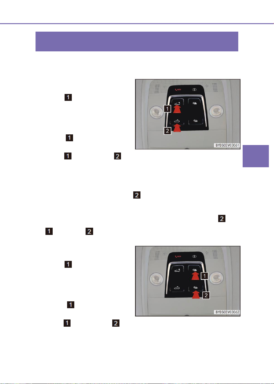
3
Controller Operations
3-4 Switch
95
Sunroof switch (if fitted)
Open the sunroof
■ If pressing the sunroof opening
button and holding it, the
sunroof will be opened manually; if
the button is released at midway, the
sunroof will stop at the current
position
■ If pressing the sunroof opening
button and released it
immediately, the sunroof will be
opened automatically, if pressing the
button or the button at
midway, the sunroof will stop at the
current position.
Open the sunshade
■ If pressing the sunshade opening
button and holding it, the
sunshade will be opened manually; if
the button is released at midway, the
sunshade will stop at the current
position.
■ If pressing the sunshade opening
button and released it
immediately, the sunshade will be
opened automatically, if pressing the
button or the button at
midway, the sunshade will stop at
the current position.
When the sunroof is operated, the power supply should be in “OK” position or the power-off
delay time range of “OFF” position.
Close the sunroof
■ If pressing the sunroof closing button and holding it, the sunroof will be closed
manually; if releasing the button at midway, the sunroof will stop at the current
position.
■ If the sunroof has been initialized, if pressing the sunroof closing button and
releasing it immediately, the sunroof will be closed automatically; if pressing the button
or the button at midway, the sunroof will stop at the current position.
Close the sunshade
Page 96
96
3-4 Switch
Warning
When opening or closing the sunroof, if a hand or head of a passenger is pinched, it
may cause extremely serious injury.
During driving process, if any part of head, hand or body is extended out of the
sunroof, if may cause serious injury or even death.
Note
If the sunroof is opened in an environment below 0 ℃ or when it is covered by ice or
snow, it may cause damage to the sunroof or the motor.
■ If pressing the sunshade closing button and holding it, the sunshade will be
closed manually; if releasing the button at midway, the sunshade will stop at the
current position.
■ If the sunshade has been initialized, if pressing the sunshade closing button and
releasing it immediately, the sunshade will be closed automatically; if pressing the
button or the button at midway, the sunshade will stop at the current position.
Sunshade linkage opening function
When the sunroof is opened, the sunshade will be opened together with the sunroof.
Anti-pinch function
If a person or object is pinched during the closing process of the sunroof or the sunshade,
the sunroof or the sunshade will be opened automatically with a distance.
Initialization method
■ If the automatic sunroof or sun visor function fails, attempt the initialization by following
procedure:
Sunroof initialization: Press and hold the sunroof OFF switch to run the sunroof to
completely closed position and hold further for 400ms.
Sunshade initialization: Press the sunshade closing button and hold it, to operate
the sunshade to the fully closed position and hold the operation for 400ms.
Page 97
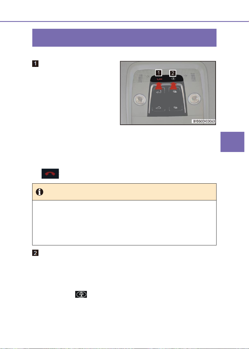
3
Controller Operations
3-4 Switch
97
B-call/E-call switch(if fitted)
E-call
E-call means emergency rescue. In
event of a serious impact or an
emergency of the vehicle, the user can
press this button to call the call center in
highest priority and the customer
service person will meanwhile acquire
the important data of the customer and
vehicle and assist the driver to escape
the danger. If required, an ambulance is
dispatched immediately to the site to
safeguard the user.
Tip
To guarantee the user’s safety, once the user presses E-call button for >2s, even if
the user ends the call, the specialist from BYD Emergency Rescue Center will call
the user.
In event of a serious safety accident, the vehicle system will automatically call the
Emergency Rescue Center. To prevent the occurrence of any emergency, the E-call
automatic dialup is answering by default.
■ When the user presses the E-call button for <2s, a dialog displaying the text “Please
press and hold SOS to call for emergency rescue” will pop up on the multimedia
display screen.
■ When the user presses the E-call button for ≥2s, the multimedia system will directly
call the emergency rescue center. To end the call, please press the End Call button
on the multimedia display screen.
B-call
■ B-call means roadside rescue. If your vehicle is malfunctioned, press this button to
send a “roadside rescue" signal to the BYD Intelligent Service Center and obtain a
series of helps, including roadside rescue, information supply, and humanistic care,
through the assistance of the BYD Intelligent Service Center.
■ When the user presses the B-call button for <2s, a dialog displaying the text “Please
press and hold to call BYD Intelligent Service” will pop up in the multimedia
display screen. To use this function, the user must press and hold this button for >2s.
Page 98
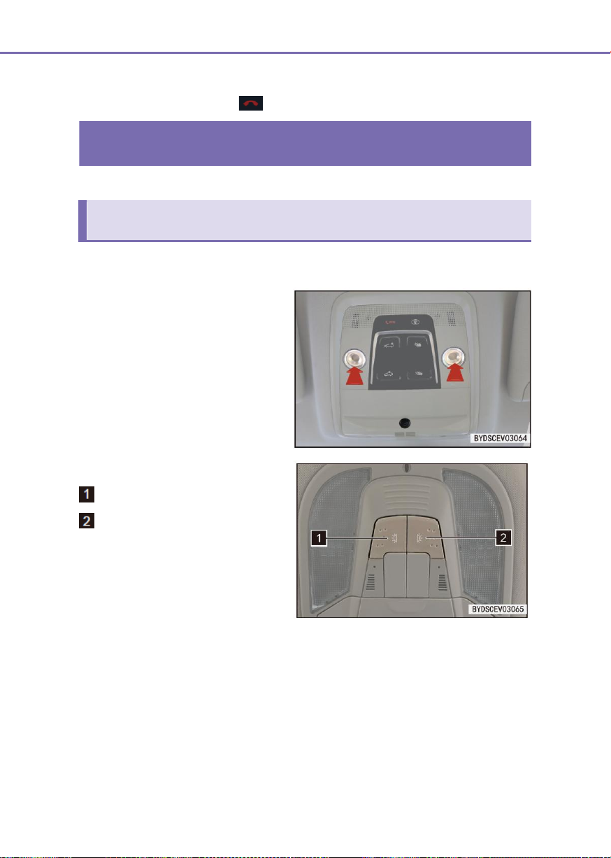
98
3-4 Switch
Indoor light switch
Front interior lamp (if fitted)
Configuration 1
Under any power position, press the
face mask of corresponding interior
lamp or reading lamp to turn on the
lamp and press again to turn off.
Camera (if fitted)
The camera beneath the interior lamp is
used for call by APP on a PAD.
Configuration 2
Left indoor light control switch
Right indoor light control switch
■ When the left/right indoor light
control switch is pressed, the
left/right indoor light will be turned
on; when the left/right indoor light
control switch is pressed again, the
left/right indoor light will be turned
off.
■ When the user presses and hold the B-call button for ≥2s, the multimedia system will
directly call the Intelligent Service Center to guarantee the user’s traveling. To end the
call, please press End Call button on the multimedia display screen.
Page 99
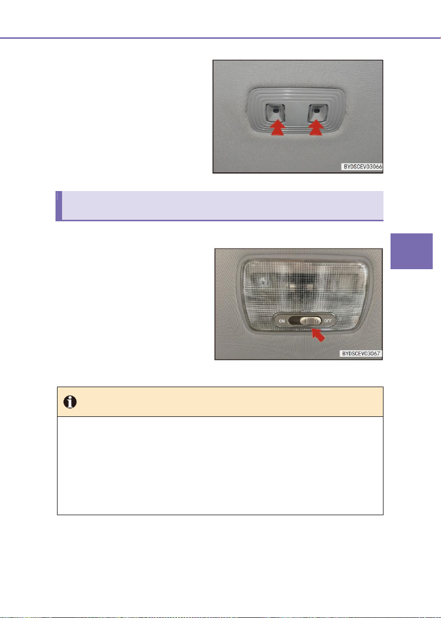
3
Controller Operations
3-4 Switch
99
■ Press the face mask of rear interior
lamp to turn on the rear interior
lamp.
Rear indoor light switch (if fitted)
ON: Turn on
OFF: Turn off
■ When it's in the middle position
(DOOR), the rear reading lamp
turns on if a door is opened and
turns off after the door is closed.
Tip
A “DOOR" switch is included on the multimedia system. With “DOOR” switch turned
on, the vehicle reading lamp turns on in low intensity when any door is opened.
When the vehicle power switch is at OFF, the reading lamp turns off in 15s after all
doors are closed. When the vehicle power switch is at “OK”, the reading lamp turns
off in 2s after all doors are closed.
When the “DOOR” switch is turned on and any door is opened, touch the
corresponding reading lamp can only switch over between low intensity and high
intensity.
Page 100
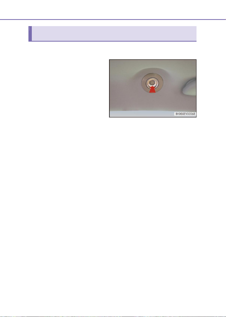
100
3-4 Switch
Side indoor light (if fitted)
■ Touch the face mask of side interior
lamp to turn on the side interior
lamp.
 Loading...