

Page 1

B-Box Professional user manual
B-Box Pro 2.5~10.0
User Manual
V2.2_July, 2017
Copyright © BYD Company Limited. All rights reversed.
Without the written consent of BYD Company, no entity or individual shall extract, copy contents of the document. It is not allowed
to be translated under any conditions.
Page 2

B-Box Professional user manual
Statement:
The product version update or any other changes to this manual is only allowed with BYD’s prior agreement. Unless otherwise
agreed, the document should be used for guidance only, all statement information and suggestions in this document do not constitute
any expression of contract or liability.
Please contact BYD directly, if you have any further questions.
BYD Lithium Battery Company Limited
TEL: 0755-8988 8888
FAX: 0755-8961 9653
Page 3

Page 3
1 GENERAL INFORMATION
................................................................................................................................................................................... 5
1.1 A
BOUT THIS MANUAL
.......................................................................................................................................................................................................5
1.2 T
ARGET GROUP
.................................................................................................................................................................................................................5
1.3 I
NTENDED USAGE
..............................................................................................................................................................................................................5
1.4 B-BOX
AND
B-P
LUS DEFINITION
....................................................................................................................................................................................5
1.5 I
DENTIFYING THE PRODUCT
.............................................................................................................................................................................................5
2 SAFETY
........................................................................................................................................................................................................................ 7
2.1 S
AFETY PRECAUTION
........................................................................................................................................................................................................7
2.2 S
AFETY GUIDELINES FOR INSTALLATION
........................................................................................................................................................................9
3 TECHNICAL PARAMETERS
............................................................................................................................................................................... 10
4 TECHNICAL TERMS EXPLANATION
............................................................................................................................................................. 11
5 PRODUCT OVERVIEW
......................................................................................................................................................................................... 12
5.1 B-BOX S
YSTEM BRIEF INTRODUCTION
.......................................................................................................................................................................12
5.2 B-BOX
CONFIGURATION TABLE
...................................................................................................................................................................................14
5.3 B-BOX S
YSTEM DIAGRAM
.............................................................................................................................................................................................14
5.4 G
ENERAL INTRODUCTION OF
BMU
..............................................................................................................................................................................15
5.5 G
ENERAL INTRODUCTION OF
B-P
LUS
2.5
.....................................................................................................................................................................15
5.6 O
PERATING ENVIRONMENT
............................................................................................................................................................................................18
5.7 B-P
LUS
2.5
ADDRESS SWITCH INTRODUCTION
.............................................................................................................................................................18
6 CLEANING AND MAINTENANCE
.................................................................................................................................................................... 19
6.1 C
LEANING
........................................................................................................................................................................................................................19
6.2 M
AINTENANCE
................................................................................................................................................................................................................19
6.2.1 Recharge requirement with norma l storage
........................................................................................................................................................19
6.2.2 Recharge requirement with over discharge storage
..........................................................................................................................................20
Page 4

Page 4
7 RESOLVE SPECIAL SITUATION
....................................................................................................................................................................... 20
7.1 B
ATTERY OVER DISCHARGED MAINTENANCE
..............................................................................................................................................................20
7.2 F
ORCE MAJEURE
.............................................................................................................................................................................................................20
8 B-BOX CONFIGURATION LIST WITH DIFFERENT INVERTER
............................................................................................................ 21
8.1 B-BOX
CONFIGURATION LIST WITH
SMA
SUNNY ISLAND-ON/OFF GRID
................................................................................................................21
8.2 B-BOX
CONFIGURATION LIST WITH
GOODWE ES-ON/O
FF GRID
..........................................................................................................................22
8.3 B-BOX
CONFIGURATION LIST WITH
GOODWE BP-O
N GRID
..................................................................................................................................22
8.4 B-BOX
CONFIGURATION LIST WITH VICTRON MULTIPLUS/MULTIGRID-ON/OFF GRID
.........................................................................................23
8.5 B-BOX
CONFIGURATION LIST WITH SOLAX-ON GRID
................................................................................................................................................23
8.6 B-BOX
CONFIGURATION LIST WITH VICTRON QUATTRO- ON/OFF GRID
.................................................................................................................24
9 NORMAL ISSUES AND SOLUTIONS
................................................................................................................................................................ 25
9.1 N
ORMAL ALARM DISPLAYED ON THE
SRC
OF
SMA
SUNNY ISLAND AND THE SOLUTION
......................................................................................25
9.2 N
ORMAL ALARM DISPLAYED ON THE
APP
OF
GOODWE
AND THE SOLUTION
.......................................................................................................26
9.3 N
ORMAL ALARM DISPLAYED ON THE SCREEN OF SOLAX AND THE SOLUTION
.........................................................................................................26
9.4 N
ORMAL ALARM DISPLAY ON THE
BMU
OF
B-BOX
AND THE SOLUTION
...............................................................................................................27
9.5 N
ORMAL ALARM DISPLAY ON
B-P
LUS
2.5
AND SOLUTION
.........................................................................................................................................27
10 WARRANTY
........................................................................................................................................................................................................... 29
11 LOGIN IN AFTER SALES SERVICE WEB
..................................................................................................................................................... 29
Page 5

Page 5
1 General Information
1.1 About this manual
This user manual introduces the B-Box product information, user guidance, safety caution items and normal failure and actions. Users can
contact the after sales service center if any abnormal failure or urgent issues occur.
1.2 Target Group
This user manual is applied to the B-BOX 2.5, B-BOX 5.0, B-BOX 7.5, and B-BOX 10.0.
1.3 Intended usage
The B-BOX can be used in household energy storage applications, including on/off -grid system. The B-BOX works with different inverter
brands and the user should refer to the configuration list of approved inverter brands recommended by BYD .
1.4 B-BOX and B-Plus definition
BYD battery box productsB-Box2.5~B-Box10.0 are defined as below:
B-Box: Battery Box
B-Plus2.5: Battery unit with nominal capacity of 2.56KWh to be installed inside the cabinet as an energy storage module.
B-Box2.5: Battery nominal capacity is 2.56 KWh (Includes 1pcs B-Plus2.5)
B-Box 5.0: Battery nominal capacity is 5.12 KWh (Includes 2pcs of B-Plus2.5)
B-Box 7.5: Battery nominal capacity is 7.68 KWh (Includes 3pcs of B-Plus2.5)
B-Box 10.0: Battery nominal capacity is 10.24 KWh (Includes 4pcs of B-Plus2.5)
1.5 Identifying the Product
The type label describes the product identification information, which is attached to the product. For safe usage, the user m ust become familiar
with the information on the type label. The type label displays:
Page 6

Page 6
Product Name:
Product Type/Nominal Capacity:
Nominal Voltage:
Max Current Discharge & Charge:
Ambient Temperature Range:
Page 7

Page 7
2 Safety
2.1 Safety precaution
Warning, notice and caution
Users are kindly requested to use the battery which is supplied by BYD Lithium Battery Company Limited in strict accordance with the
datasheet and remarks included at the end of this document .
BYD Lithium Battery Co., Ltd. will not guarantee or accept liability for a produ ct installed and operated not in accordance to the guidance manual
and resulting in an accident.
WARNING
Do not crush the battery and always dispose according to safety regulations (Do not dispose in fire or water).
Recharge battery at least every 6 months (when in storage).
Once discharged, recharge battery within 7 days.
Do not expose to temperatures above 55℃ and keep out of direct sunlight.
Ensure secure grounding. Do not reverse the front panel.
Do not short/reverse polarity or connect in series.
Disconnect from power and load before maintenance.
Only be operated by qualified professionals.
Store according to related standard.
Do not put one battery on top of another when unpackaged.
In the process of transportation and storage, the goods are not allowed to be stacked in layers or at a height greater than specified.
When increasing the battery capacity, users should first power off the battery and other power inputs.
B-BOX products can only be used in home energy storage applications, and their use is not allowed for life -sustaining medical devices and
automotive applications.
Page 8
Page 8
NOTICE
Continuous operation of a damaged B-Box can lead to a dangerous situation that may cause serious injury due to electrical shock. B-Box can
only be operated when it is technically faultless and in an operationally safe state.
Regularly check the B-Box for visible damage making sure that all safety equipment is freely accessible at all times. If a B -Box is damaged,
do not touch it.
Please contact a BYD after sales service supplier if a significant event message displays on the LCD or APP of the inverter .
CAUTION
Li-ion battery inside. When disassembling the system, do not intentionally short the positive (+) and negative (-) terminals with metallic
objects.
All works on system and electrical connections must be carried out by qualified personnel only. B -Box provides an emergency switch to be
used for urgent situations.
A potentially hazardous circumstance such as excessive heat or electrolyte mist may occur due to incorrect operation, damage or abuse. If the
safety precautions and the warning messages described are not fully understood, or if you have any questions, please contact after sales service
for guidance. The safety section may not include all regulations for your region.
Personnel working with B-Box products must review applicable federal, state and local regulations as well as the industry standards regarding
this product.
When transporting the system packaged as a bundle, remove the battery from the cabinet and transport them separately .
Page 9
Page 9
2.2 Safety guidelines for installation
CAUTION
Li-ion battery (energy storage unit) inside. When assembling the system, do not intentionally make a short connection between the positive (+)
and negative (-) terminals of the battery box with a metallic object.
All works on the B-Box and electrical connections must be carried out by qualified personnel only.
B-Box provides a safe source of electrical energy when operated as intended and as designed.
Potentially hazardous circumstances such as excessive heat or electrolyte mist may occur under improper operating conditions, damage,
misuse and abuse.
The following safety precautions and the warning messages described in this section must be observed. If any of the following precautions are
not fully understood, or if you have any questions, contact customer service for guidance. The Safety Section may not include all regulations
for your region; personnel working with B-Boxes must review applicable federal, state and local regulations as well as the industry standa rds
regarding this product.
Installation personnel cannot wear watches, etc., to avoid short circuit and accidental damage .
CAUTION
Due to the heavy weight of BYD B-Box 2.5~10.0, please use strong packaging and safety protection equipment during transportation, to
ensure safety and avoid accidental damage.
Page 10

Page 10
3 Technical parameters
When B-BOX works in different temperatures, the charge and discharge current will be adjusted automatically. For detailed parameter settings,
please refer to the table below:
Parameter setting of charge current in various temperature
Protect temp./Resume temp.(℃)
Normal current(A)
-7~2
0.06C*N
2~12
0.12C*N
12~50
0.7C*N
Remarks:
1. Effective time is 2mins when changing from one temperature range to another.
2. N=B-Plus2.5 battery quantity
B-Box Pro2.5
B-Box Pro5.0
B-Box Pro7.5
B-Box Pro10.0
Battery Type
Lithium Iron phosphate battery
Battery module
B-Plus2.5
Nominal Battery Energy
2.56
5.12
7.68
10.24
Max output power(KW)
2.56
5.12
7.68
10.24
Usable battery energy(KWh)(100% DOD, 0.5C charge
&discharge at @+25℃)(KWh)
2.56
5.12
7.68
10.24
Nominal voltage(V)
51.2
Operating Voltage Range(V)
43.2~56.4
Ambient Temperature Range(℃)
-10~+50
Communication
RS485/CAN
Cabinet Net Dimension(W*D*H mm)(Without ground feet)
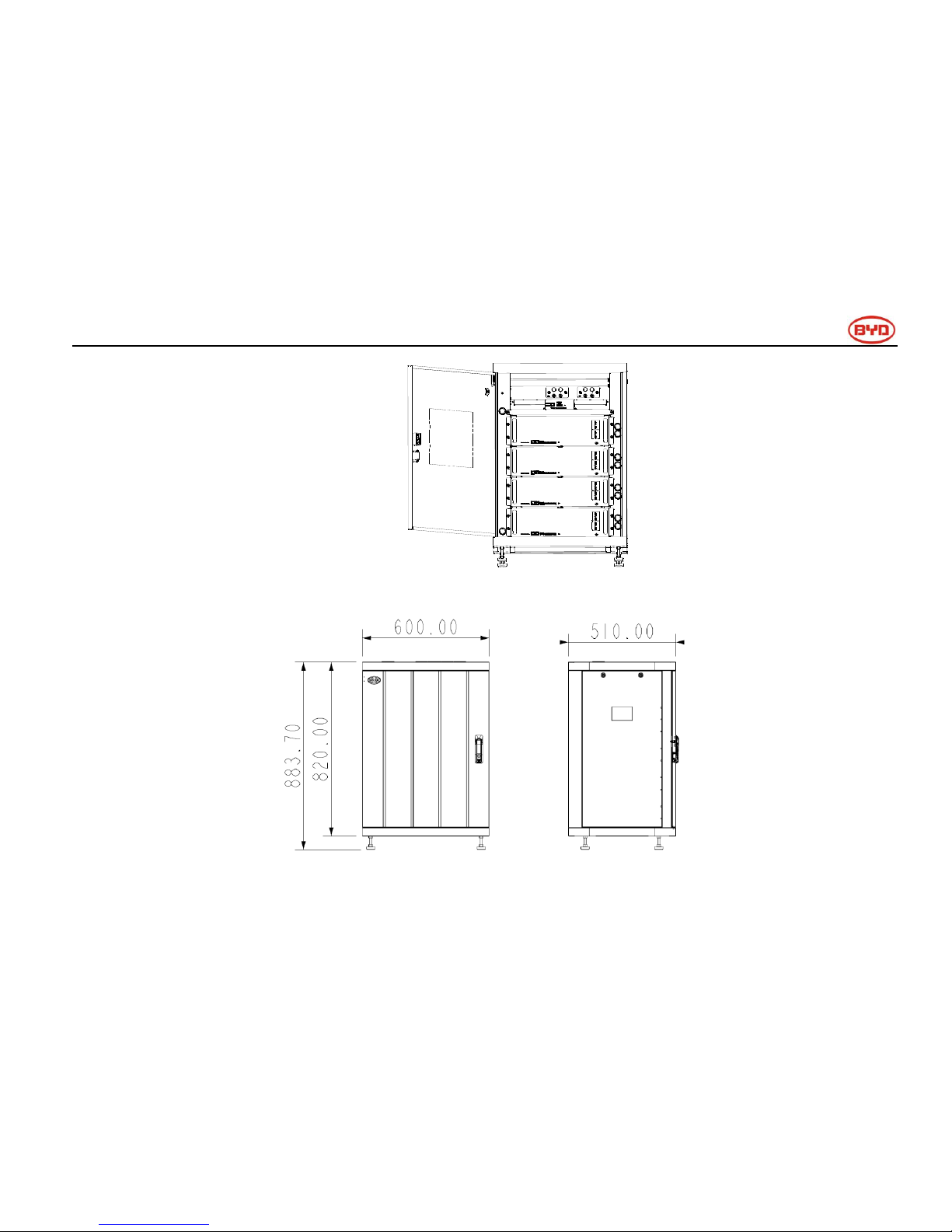
600* 510* 883
Net Weight(Kg)
79
113
146
180
IP level
IP20
Page 11

Page 11
Discharge current control with temperature
Protect temp./Resume temp.(℃)
Normal current(A)
-20~50/(-15-50)
0.7~1C*N
Remarks:
1. N= B-Plus2.5 battery quantity
4 Technical terms explanation
No.
Terms
comment
1
Discharge
Battery output power for load
2
Charge
Battery power supply(such as DC charger)
3
Full charged
Battery had been full charged, SOC is 100%.
4
Idle
Battery is on status of neither charge nor discharge and has not been fully charged.
5
Shutdown mode
Power off
6
SOC
State of Charge
7
SW
Software
8
HW
Hardware
9
Battery voltage
The voltage between B+/B-
10
Pack voltage
The voltage between P+/P-
11
Cell voltage
Single cell voltage
12
Failure
Battery or BMS are broken, and unit needs replacement
13
Alarm
Battery will stop charging or discharging immediately
14
Protect
Battery stops charging or discharging (e.g. cell is overvoltage). Operation can resume at
a later stage.
15
Over discharged
Battery module or batteries overvoltage, need to be recharged timely
Page 12
Page 12
5 Product overview
5.1 B-BOX System Brief introduction
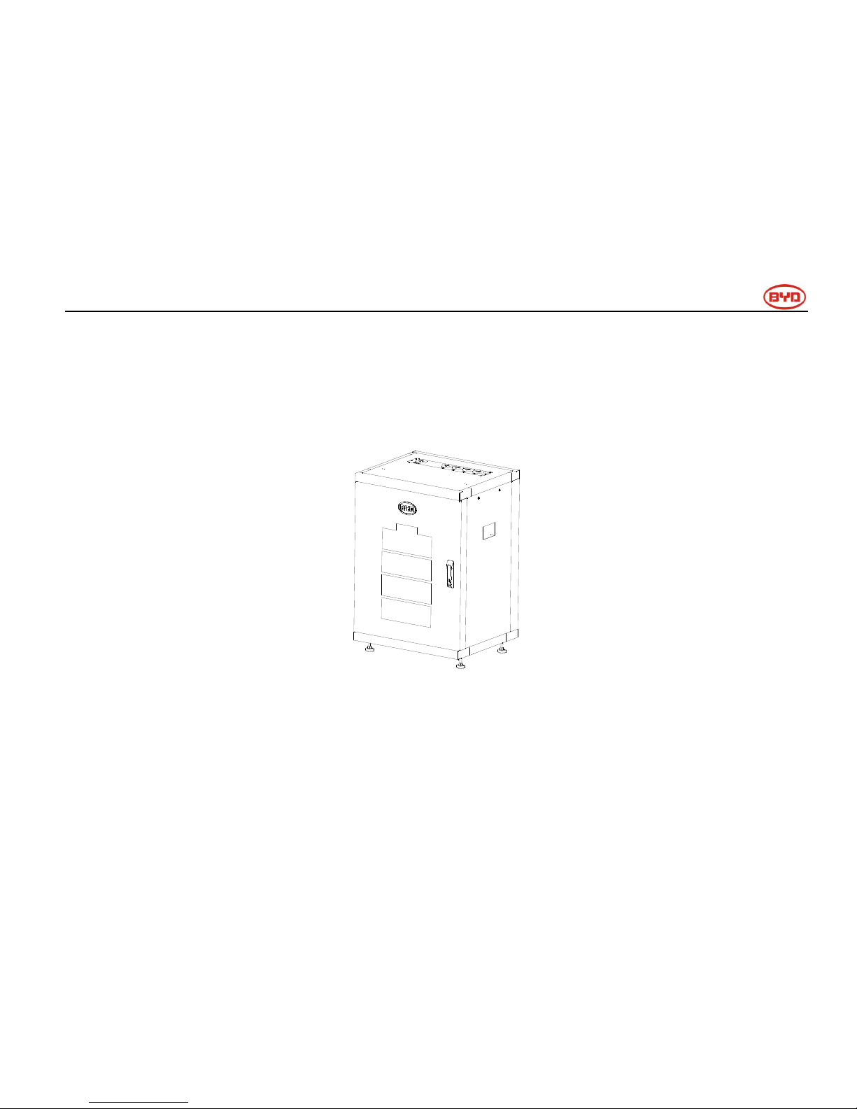
B-Box is the short name for battery box, the energy storage part in the electric power system of a household, and the B-box carries BYD’s
lithium batteries offering excellent performance. There are 1/2/3/4 pcs batteries modules in each box, and the box supports p arallel connection
to expand capacity from 2.5KWh to 80KWh, which can meet various capacity requirement for customers.
External drawing
Page 13
Page 13
Internal drawing
Structure dimension drawing
Page 14
Page 14
5.2 B-BOX configuration table
No.
Component
Name
Description
1
Cabinet
B-Box Cabinet
The cabinet is used to accommodate the B-Plus 2.5 modules and
provide DC output (It can take max 4pcs B-Plus 2.5)
2
Battery
B-Plus2.5
Battery module with 51.2V 50Ah, BYD’s P/N is: U3A1-50P-A.
3
BMU
BMU
Battery management unit. Provides communication with external
equipment.
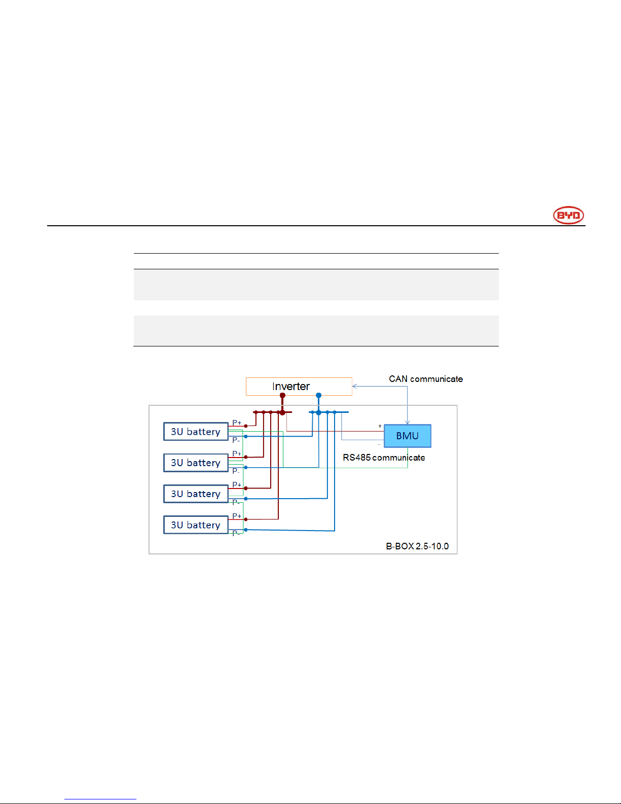
5.3 B-BOX System diagram
System diagram
Page 15
Page 15
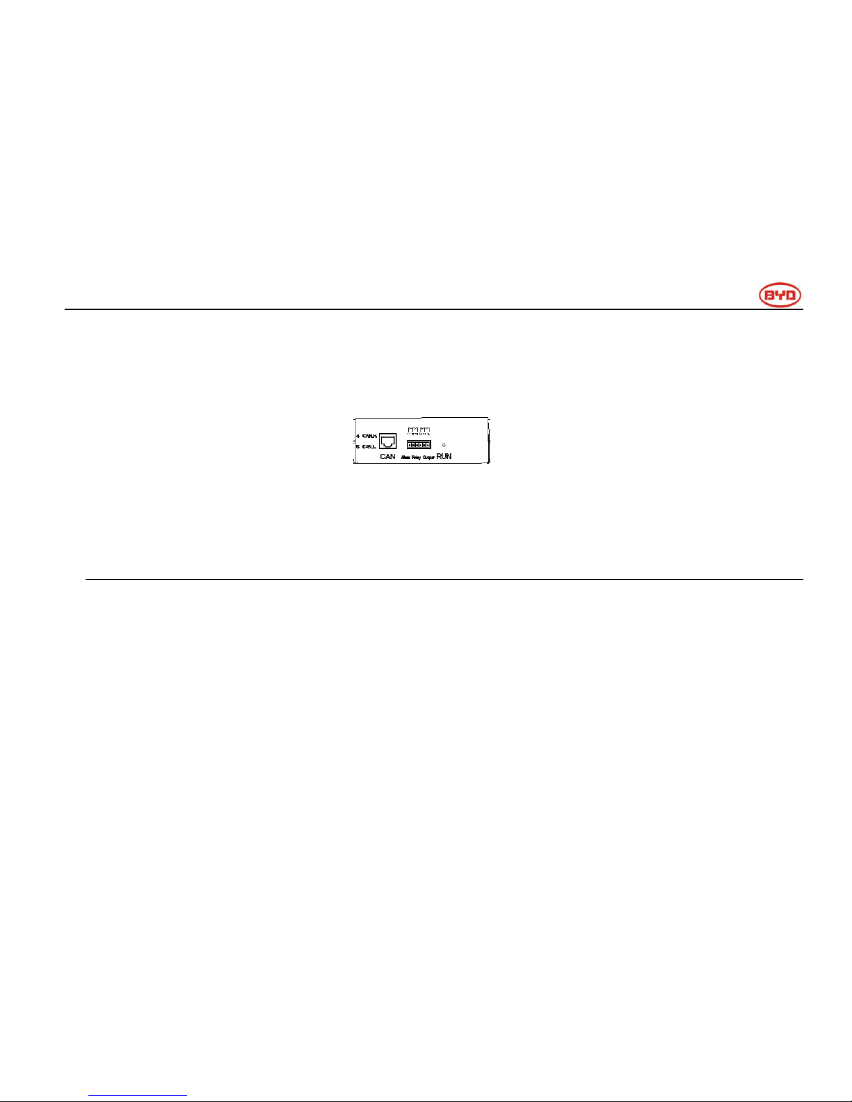
5.4 General introduction of BMU
BMU is the battery management unit installed in the cabinet; its function is to manage the battery’s charge and discharge, co llect information
from the battery and report to the inverter..
Main function:
CAN / RS485 communication with inverter
RS485 communicate with battery/BMS
Dry contact terminal
Other Communication interface for maintenance
Charge and discharge management
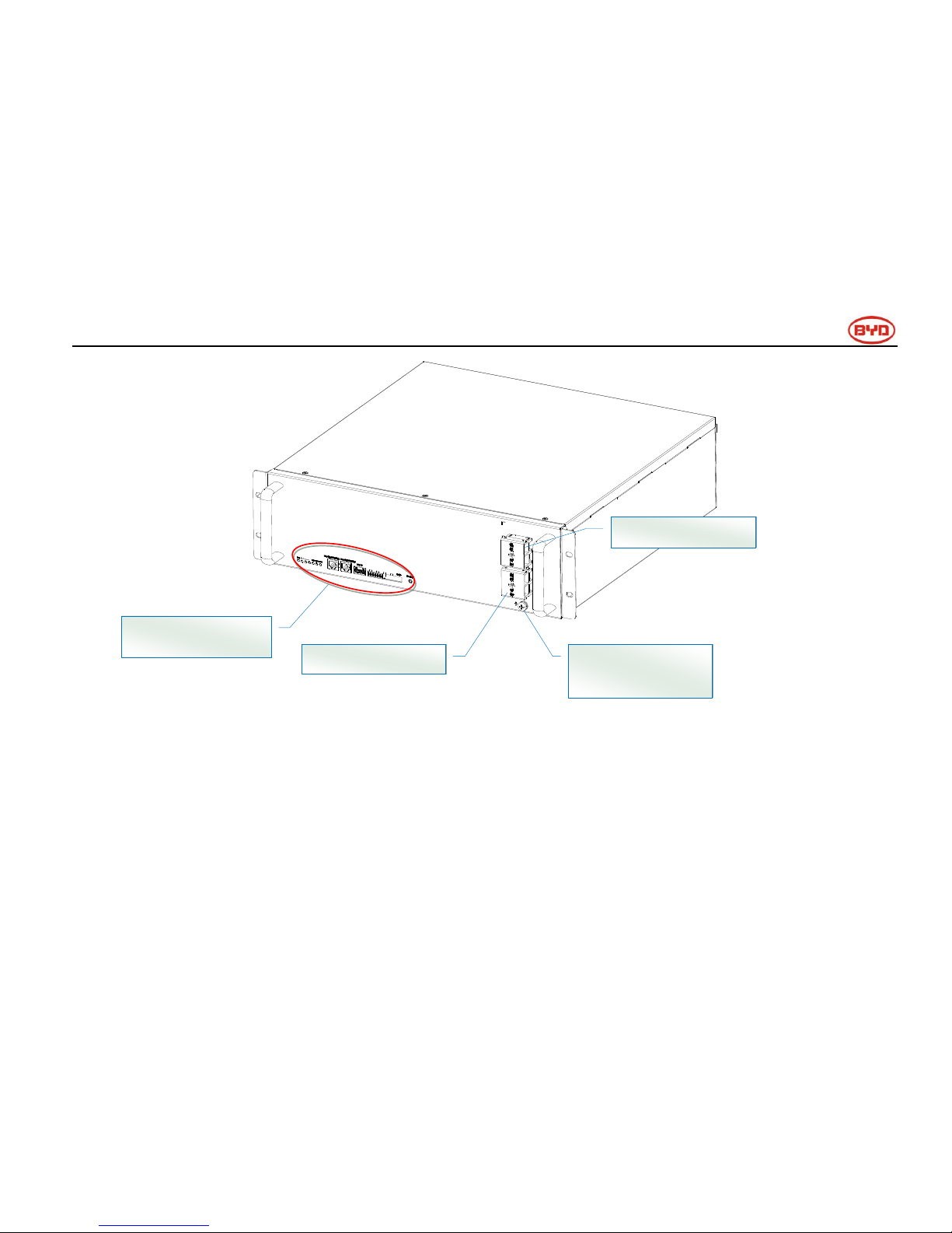
5.5 General introduction of B-Plus 2.5
B-Plus is the commercial name of BYD’s U3A1-50P-A backup battery with 51.2V & 50Ah which is designed for energy storage applications.
The B-Plus 2.5 is an integrated battery which consists of shell, BMS and cells.
⑩
Page 16
Page 16
B-Plus 2.5 overview
Display and communication interface
Display and
communicate interface
GND: Grounded
terminal
P-: Negative terminal (DC+)
P+: Positive terminal (DC-)
Page 17
Page 17
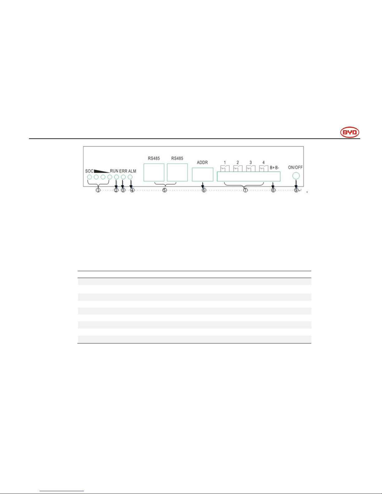
Display and communication interface
No.
Interface
Mark
Function
SOC LED
SOC
Indicates State of capacity of battery
RUN LED
RUN
Indicates the Plus is running status
ERR LED
ERR ADDR
Indicates error status
ALM LED
Alarm
Indicates alarm status
RJ45 terminal
RS485
Communication ports
Address
ADDR
When parallel connection, need setting address.
Alarm relay output
1.2.3.4
Not used
Test terminal
B- B+
Measures battery voltage when testing.
ON/OFF
ON/OFF
Activates battery when no external powers add on battery.
Page 18
Page 18
5.6 Operating environment
Operating environment parameters
No.
Item
Requirement
Unit
Remark
Min.
Typical
Max.
1
Discharging temperature
-10
25
50
℃
2
Charging temperature
-10
25
50 ℃
3
Relative humidity
5
95
%
4
Absolute humidity
0.26
25
g/m3
5
Elevation - 2000
-
m
6
IP level
20
5.7 B-Plus 2.5 address switch introduction
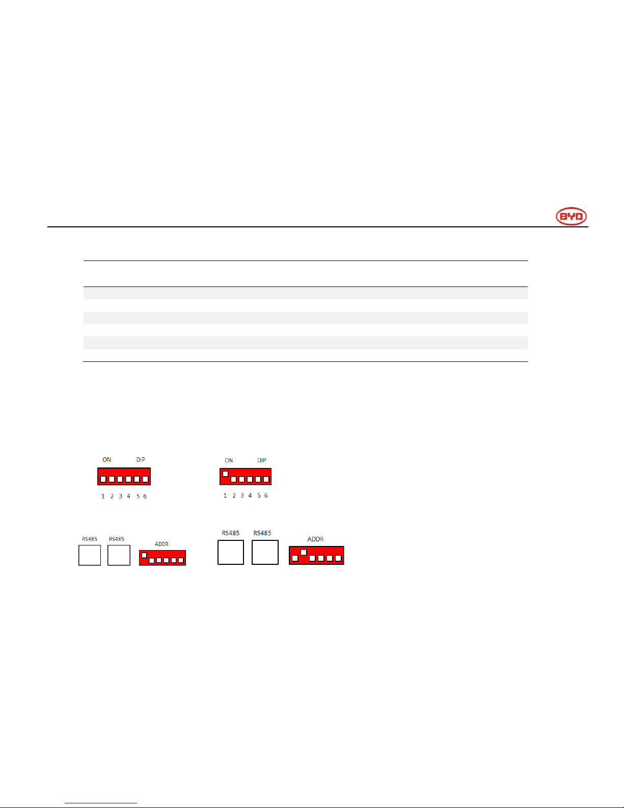
After finished the battery installation, installer should setup battery address through the “ADDR” switch.
“ADDR” switch introduction:
Function: Communication between battery and BMU. The BMU will communicate with external equipment when using CAN
communication.
Each DIP switch definition:
There are 6 bit switches, keeping it down means “0”, turn up the switch to “ON” means “1”.
Address: 000000 Address:100000
For example: when two batteries are in use, “ADDR” setting shows:
Page 19
Page 19
No.1 battery address: 100000 No.2 battery address: 010000
Please refer to the configuration list in Appendex1.
Note: Make sure of the highest address of BMS connecting to the BMU when communicating with the inverter .
6 Cleaning and maintenance
6.1 Cleaning
The B-BOX system is recommended to be cleaned periodically. If the enclosure is in a dirty condition, please use a soft and dry brush or a
vacuum to remove the dirt.
Do not use liquids such as solvents, abrasives or corrosive liquids in the enclosures.
6.2 Maintenance
6.2.1 Recharge requirement with normal storage
The B-BOX should be installed in a position with a temperature range of -10
℃~
+50℃ and where the humidity is less than 80%.The
load-bearing of the battery’s packaging is less than 300Kg, so stacking more than 7 modules is not recommended..
When the battery stored for a long time, need a regular maintenance according to the following tab le. Charge battery with current of 0.5C
(25A) for 1 hour when maintenance.
Storage parameters under different storage conditions-1
Storage environment temperature
Relative humidity of storage environment
Storage time
SOC
Below -20℃
/
Avoid
/
-20~25℃
5%~70%
≤12 months
30%≤SOC≤60%
CAUTION:
When users need to clean the B-BOX, please switch off the system firstly.
Page 20

Page 20
25~35℃
5%~70%
≤6months
30%≤SOC≤60%
35~45℃
5%~70%
≤3months
30%≤SOC≤60%
Above 45℃
/
Avoid
/
6.2.2 Recharge requirement with over discharge storage
If module is over-discharged during storage, the module will be damaged after several days if the module has not been charged in time.
Storage parameters under different storage conditions-2
Storage environment temperature
Storage time
-20~25℃
≤15 days
25~45℃
≤7 days
7 Resolve special situation
7.1 Battery over discharged maintenance
In the case of power cuts, continuous rainy days etc., the battery may over-discharge. It will still provide limited energy, but users should pay
attention to the backup time of the battery.
7.2 Force Majeure
Catastrophic accidents, including lightning, floods, earthquakes, fires and other natural disasters, can bring unpredictable damage to the whole
system.
Page 21

Page 21
8 B-Box configuration list with different inverter
8.1 B-BOX configuration list with SMA sunny island-On/Off grid
1 Phase on Grid
Inverter Type
B-Plus 2.5
Cabinets
SI 3.0M
≥1
≥1
SI 4.4M
≥1
≥1
SI 6.0H
≥1
≥1
SI 8.0H
≥1
≥1
Remark: Maximum B-Plus quantity is 32, Cabinet quantity is 8.
3 Phase off Grid
Inverter Type
B-Plus 2.5
Cabinets
SI 3.0M
≥3
≥1
SI 4.4M
≥4
≥1
SI 6.0H
≥4
≥1
SI 8.0H
≥4
≥1
1 Phase on Grid
Inverter Type
B-Plus 2.5
Cabinets
SI 3.0M
≥3
≥1
SI 4.4M
≥3
≥1
SI 6.0H
≥5
≥2
SI 8.0H
≥5
≥2
3 Phase off Grid
Inverter Type
B-Plus 2.5
Cabinets
SI 3.0M
≥8
≥2
SI 4.4M
≥8
≥2
Page 22

Page 22
SI 6.0H
≥12
≥3
SI 8.0H
≥12
≥3
Remark: Maximum B-Plus quantity is 32,Cabinet quantity is 8.
8.2 B-BOX configuration list with GOODWE ES-On/Off grid
1 Phase on Grid
Inverter Type
B-Plus 2.5
Cabinets
3.6kW
≥1①
≥1
4.6kW
≥1①
≥1
1 Phase off Grid
Inverter Type
B-Plus 2.5
Cabinets
3.6kW
≥2
≥1
4.6kW
≥2
≥1
Remark: Maximum B-Plus quantity is 32,Cabinet quantity is 8.
①This configuration is only for self-consumption application
8.3 B-BOX configuration list with GOODWE BP-On grid
1 Phase on Grid
Inverter Type
B-Plus 2.5
Cabinets
2.5kW
≥1
≥1
Remark: Maximum B-Plus quantity is 32, Cabinet quantity is 8.
Page 23

Page 23
8.4 B-BOX configuration list with Victron Multiplus/Multigrid-On/Off grid
1 Phase on Grid
Inverter Type
B-Plus 2.5
Cabinets
3KVA
≥1
≥1
5KVA
≥1
≥1
1 Phase off Grid
Inverter Type
B-Plus 2.5
Cabinets
3KVA
≥3
≥1
5KVA
≥5
≥2
3 Phase on Grid
Inverter Type
B-Plus 2.5
Cabinets
3KVA
≥3
≥1
5KVA
≥4
≥1
3 Phase off Grid
Inverter Type
B-Plus 2.5
Cabinets
3KVA
≥8
≥2
5KVA
≥12
≥3
8.5 B-BOX configuration list with Solax-On grid
1 Phase on Grid
Inverter Type
B-Plus 2.5
Cabinet
SK-SU 3000
≥1
≥1
SK-SU 3700
≥1
≥1
SK-SU 5000
≥1
≥1
Page 24

Page 24
8.6 B-BOX configuration list with Victron Quattro- On/Off grid
1 Phase on Grid
Inverter Type
B-Plus 2.5
Cabinet
5KVA
≥1
≥1
8KVA
≥1
≥1
10KVA
≥1
≥1
15KVA
≥1
≥1
1 Phase off Grid
Inverter Type
B-Plus 2.5
Cabinet
5KVA
≥3
≥1
8KVA
≥5
≥2
10KVA
≥6
≥2
15KVA
≥9
≥3
3 Phase on Grid
Inverter Type
B-Plus 2.5
Cabinet
5KVA
≥3
≥1
8KVA
≥4
≥1
10KVA
≥5
≥2
15KVA
≥6
≥2
Page 25

Page 25
3 Phase off Grid
Inverter Type
B-Plus 2.5
Cabinet
5KVA
≥9
≥3
8KVA
≥15
≥4
10KVA
≥18
≥5
15KVA
≥27
≥9
9 Normal issues and solutions
9.1 Normal alarm displayed on the SRC of SMA sunny island and the solution
SMA SRC
Reason
Solution
F221
External Alarm-Invalid Bat Type
Reset battery type to "Li" on SRC.
F920(XA01General)
1.All the batteries fail to communicate at
the same time
2.BMU and battery fail to communicate via
RS485
1.Inspect whether the RS485 communication
cable has been connected correctly and
securely
2.Inspect DIP switch settings according to the
setting of DIP switch guidance in user manual
3.Change BMU in cabinet
F921(XA02DcHiVolt)
External Alarm - Battery High Voltage
If the red led of the B-Plus 2.5 is on, please
contact the service provider to change the
battery. If not, check the system settings
according to the guidelines.
F922(XA03DcLoVolt)
External Alarm - Battery Low Voltage
F923(XA04DcHiTmp)
External Alarm - Battery High Temp
F924(XA05DcLoTmp)
External Alarm - Battery Low Temp
F925(XA06DcHiTmpC)
External Alarm - Battery High Temp
Charge
F926(XA07DcLoTmpC)
External Alarm - Battery Low Temp
Charge
Page 26

Page 26
F927(XA08DcHiCur)
External Alarm - Battery High Current
Discharge
F928(XA09DcHiChgCur)
External Alarm - Battery High Current
Charge
F930(XA11Short)
External Alarm - Short circuit
1.Power off;
2.Inspect short connection of cable between
P+ and P-
3.If short connection is confirmed, please
reconnect cable correctly
4.Restart battery
F931(XA12Bms)
External Alarm - BMS internal
If the red led of the B-Plus 2.5 is on, please
contact the service provider to change the
battery. If not, check the system settings
according to the guidelines.
F932(XA13CellBal)
External Alarm - Cell imbalance
F952
External Alarm –Ext BMS Timeout
1.Check the CAN communication to make
sure it is connected properly
2.Change BMU
9.2 Normal alarm displayed on the APP of GOODWE and the solution
APP of GOODWE
Reason
Solution
BMS status: Battery communication
fail
Inverter and BMU communication
failure
1.Inspect whether the CAN
communication cable has been connected
correctly and reliability
2.Change BMU in cabinet
9.3 Normal alarm displayed on the screen of Solax and the solution
Screen of Solax
Reason
Solution
BMS LOST
Inverter and BMU communication failure
1. Inspect whether the CAN communication
cable has been connected correctly and
reliability.
2. Change BMU in cabinet.
Page 27

Page 27
9.4 Normal alarm display on the BMU of B-BOX and the solution
LED of the BMU
Reason
Solution
Flash 1 time
Inverter and BMU communication failure
1.Inspect whether the CAN communication
cable has been connected correctly and
reliability
2.Change BMU in cabinet;
Flash 2 times
Battery not found
Check whether the BMU and first battery are
connected properly
Flash 3 times
Cell not found
Check the battery SOC LEDs is
merry-go-round, check if the communication
cable and the address of the corresponding
battery are set correctly.
Flash 4 times
Any battery failure
Check if the battery light stays lightening, and
if so, please contact your installer to replace
the battery.
9.5 Normal alarm display on B-Plus 2.5 and solution
B-Plus display info
Reason
Solution
LED
Yellow led(Alarm) blinks for 0.5Hz, other
LEDs are off ;
Battery is switched
off abnormally
Press ON/OFF button for 2-3 seconds to
restart the battery, if the battery cannot be
resumed, contact the service provider;
The merry-go-round (10s cycle)
Communication
connection timeout
Check the communication cable
1/3 and 2/4 is blinking
Update status
If not update the firmware, reset the
battery.
Yellow led (Alarm)
is
normally on
1. press on/off button for 1S and release,
hear a short buzzer sound;
2.run lights stay lit, ALM LED is
1time
Under voltage
(BAT or CELL)
Automatically resume
2times
Over charge
Automatically resume
Page 28

Page 28
blinking, showing alarm;
3times
Low temperature
charge over-current
Automatically resume
4times
Charge short circuit
Automatically resume
5times
Discharge short
circuit
Automatically resume
6times
Parallel short
circuit
Automatically resume
7times
Discharge
over-current
protection
Automatically resume
8times
High temperature
protection
Automatically resume
9times
Low temperature
protection
Automatically resume
10times
PACK over voltage
protection
Automatically resume
Red led (Err)
is
normally on
1) press the on/off button press for 1S and
release, hear short buzzer sound;
2) run lights stay lit, ERR LED is
blinking, showing alarm;
1time
Voltage sensor
failure
Change the battery
2times
Temperature sensor
failure
Change the battery
3times
Charging circuit
failure
Change the battery
4times
Discharge circuit
failure
Change the battery
5times
Batteries failure
Change the battery
6times
536 communication
failure
Change the battery
Page 29

Page 29
Buzzer
15S for the cycle, each time the buzzing
number of successive rings
4times
Reverse, short
circuit
1.Power off;
2.Inspect short/reverse connection of
cable between P+&P-;
3.If short/reverse connection is
confirmed, please reconnect cable
correctly;
4.restart battery;
3times
Batteries failure
Change the battery
2times
Voltage sensor
failure,
Temperature sensor
failure
Change the battery
1time
Charging/Discharge
circuit failure
Change the battery
10 Warranty
BYD provides warranties only when the product is installed and used according to the description of user manual / installatio n manual /
warranty letter.
11 Login in after sales service web
In order to get prompt after sales service after installation, please login your B -BOX information in our after sales service operation online
portal.
For technical problems or inquiries for use, please contact our after sales service partner.
The following information is required for timely customer service.
Page 30

Page 30
Product type
Serial Number
Connected PV module type and number
Option equipment
Any problems please contact us by below address:
Contact us:
China
BYD LITHIUM BATTERY Co., LTD
Customer Service Mailbox: [email protected]
Telephone: +86 0755 89888888
Address: No.1, Baoping Road, Baolong lndustrial Town Longgang Shenzhen, 518116, P.R. China
Germany
EFT Systems GmbH
Customer Service Mailbox:
Telephone: +49-9352 8523999
Address: Buchenstraße 37, 97816 Lohr am Main, Germany
Australia
Alps Power Pty Ltd
Customer ServiceMailbox: [email protected]
Telephone: +61478 140 287
Address: U201 15Chatham Road West Ryde NSW 2114 Australia
 Loading...