

Page 1

B-Box Residential installation guidance
1/ 43
Installation Guidance
B-Box Res2.5~10.0
Rev1.0_April.2017
Page 2

B-Box Residential installation guidance
2/ 43
Content
Safety
........................................................................................................................................................................................................ 4
1 Product Overview
................................................................................................................................................................................ 5
2 Cabinet introduction
............................................................................................................................................................................ 6
3 Cable outlet of cabinet
......................................................................................................................................................................... 7
4 B-Plus2.5 interface and terminal introduction
................................................................................................................................. 8
4.1 Display and communicate interface ................................................................................................................................................................................ 8
5Preparations
........................................................................................................................................................................................... 9
5.1 Installation notice
.............................................................................................................................................................................................................. 9
5.2Package information and system configuration list
..................................................................................................................................................... 10
5.3 Configuration list
............................................................................................................................................................................................................. 11
5.4 Installation Tools
............................................................................................................................................................................................................. 12
5.5 Personal protective equipment
....................................................................................................................................................................................... 13
6Installation
........................................................................................................................................................................................... 14
6.1 Open the package
............................................................................................................................................................................................................ 14
6.2 Disassemble thefixed seat& door and pallet ............................................................................................................................................................... 15
6.3Fix the frame on the wall, then fix the cabinet with the fixing frame ......................................................................................................................... 16
6.4Battery installation ............................................................................................................................................................................................................ 17
6.5Connect cables with battery ............................................................................................................................................................................................ 18
7Parallel connection between multi B-Box
........................................................................................................................................ 19
7.1Communication cable connection drawing
................................................................................................................................................................... 19
7.2Grounded cable connection between several B-Box
................................................................................................................................................... 20
7.3Power cable connection between several B-Box
......................................................................................................................................................... 21
8Battery address set up
........................................................................................................................................................................ 22
8.1“ADDR” switch introduction
.......................................................................................................................................................................................... 22
8.2 Battery address setting list (from 1~32 batteries)
....................................................................................................................................................... 23
9Connect to inverter
............................................................................................................................................................................. 24
9.1 CAN cable connection
.................................................................................................................................................................................................... 24
9.2 Power cable connection
.................................................................................................................................................................................................. 25
Page 3

B-Box Residential installation guidance
3/ 43
10Start system
........................................................................................................................................................................................ 26
10.1System activity procedures when B-Box connect to SMA Sunny Island
.............................................................................................................. 26
10.2 System activity procedures when B-Box connect to GOODWE inverter
............................................................................................................ 29
10.3 System activity procedures when B-Box connect to Victron inverter
.................................................................................................................. 31
10.4 System activity procedures when B-Box connect to Solax inverter
...................................................................................................................... 33
11Stop system
......................................................................................................................................................................................... 35
Appendix 1
............................................................................................................................................................................................. 36
Appendix 2
............................................................................................................................................................................................. 42
Installation Video Website:http://www.byd.com/energy/b-box-25.htm
Page 4
B-Box Residential installation guidance
4/ 43
Safety
CAUTION
:
Li-Ion battery (energy storage unit) inside. When assembling the system, do not intentionally make a short condition between the positive (+) and negative (-)
terminals of the battery box with a metallic object.
All work on the B-Box and electrical connections must be carried out by qualified personnel only. B-Box provides a safe source of electrical energy when
operated as intended and as designed.
Potentially hazardous circumstances such as excessive heat or electrolyte mist may occur under improper operating conditions, damage, misuse and/or abuse.
Personnel working with B-Box must review applicable federal, state and local regulations as well as the industry standards regarding this product.
Installation personnel cannot wear watches, etc., to avoid short circuit and human damage.
When Increase battery, should power off the battery and other power input first.
Ensure reliable grounding. Do not reverse the front panel.
Can't use the deformation of the battery.
By checking to verify the installation Settings are correct.
Need to clean, smooth, waterproof, and so on and so forth, the installation.
Page 5
B-Box Residential installation guidance
5/ 43
1 Product Overview
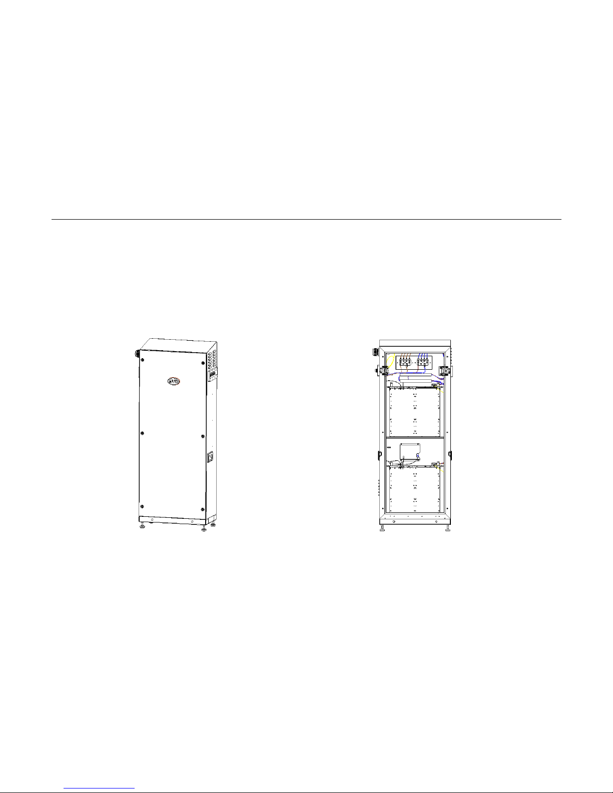
BYD battery box products B-Box Res 2.5~10.0 as the energy storage parts can be used in off-grid & on-grid energy storage system.
Page 6
B-Box Residential installation guidance
6/ 43
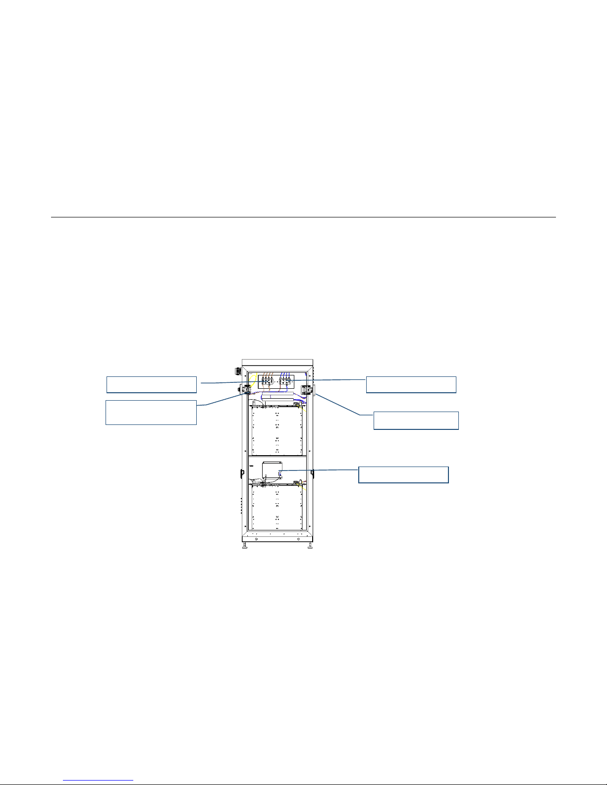
2 Cabinet introduction
Overview of B-Box
Internal view of B-Box
Battery disconnector
DC BUS: Positive
DC BUS: Negative
Main circuit disconnector
BMU
Page 7
B-Box Residential installation guidance
7/ 43
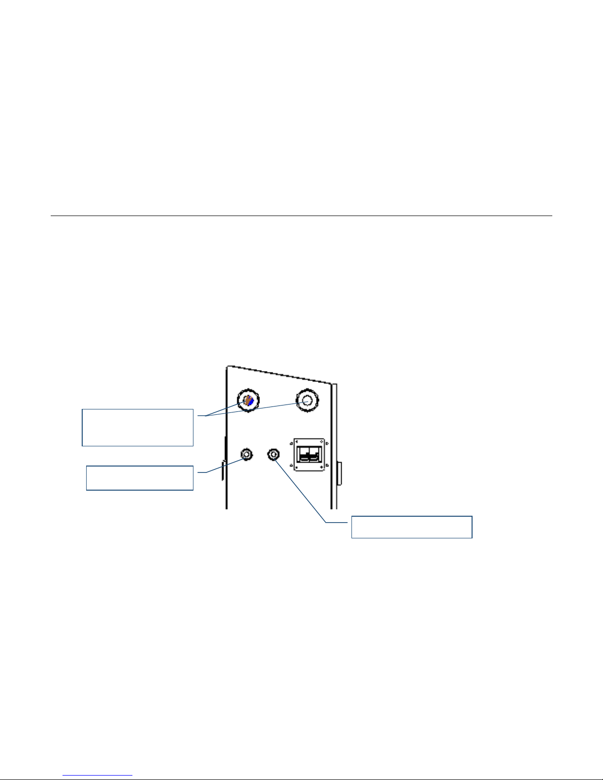
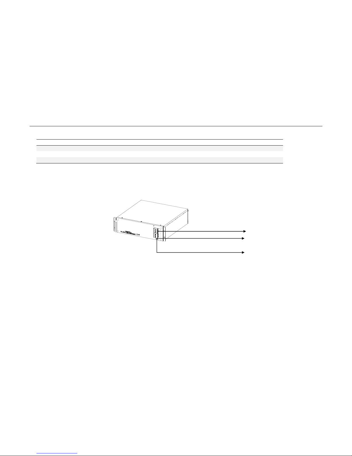
3 Cable outlet of cabinet
Power cable to inverter
②Grounded cable to inverter
③Communication cable to inverter
Page 8
B-Box Residential installation guidance
8/ 43
No.
Interface
Mark
Function
B+/B-output
B+/B-
Power cable from inverter
GND
GND
Grounded cable from inverter
CAN
CAN
CAN communication cable
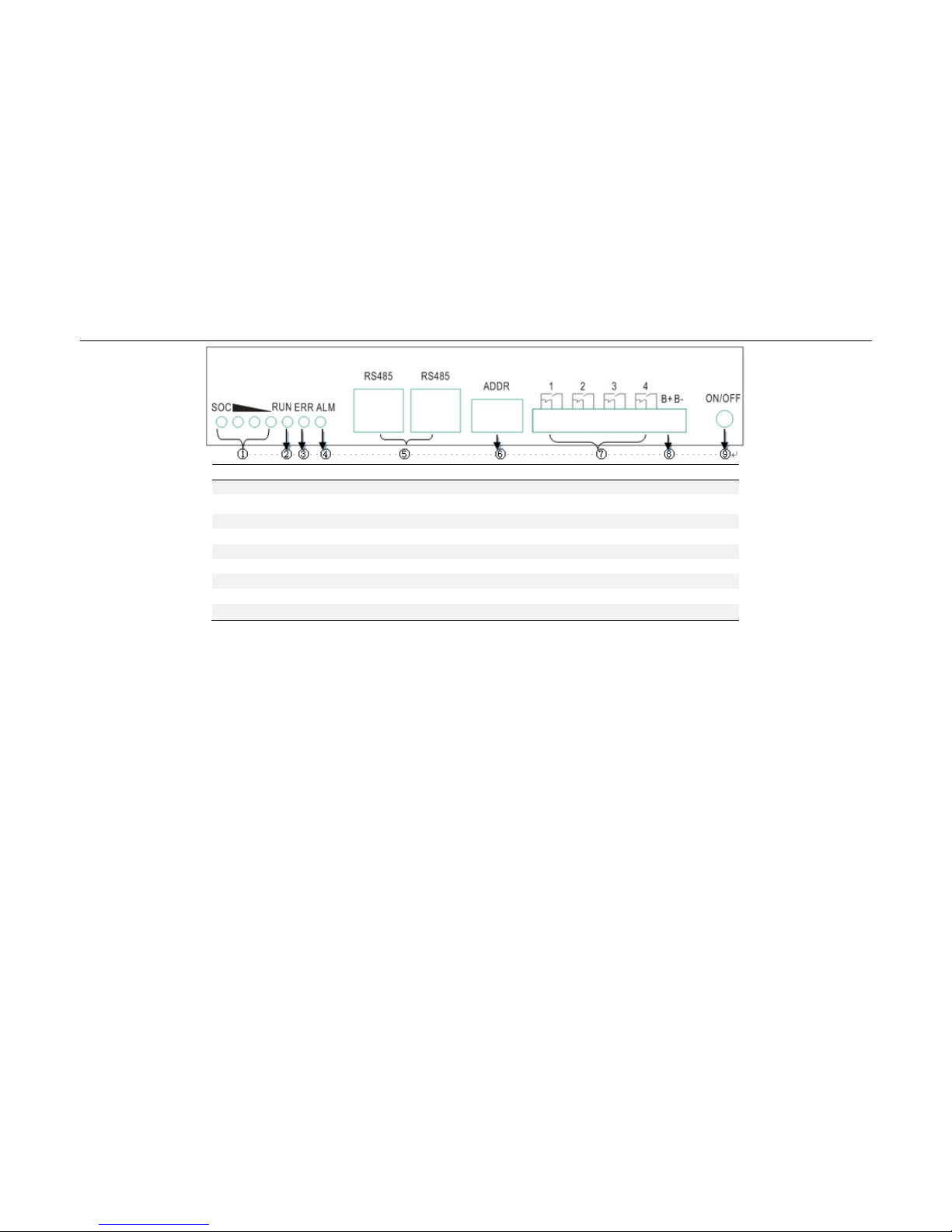
4 B-Plus2.5 interface and terminal introduction
4.1 Display and communicate interface
P-:Negative terminal
P+:Positive terminal
GND:Grounded terminal
Page 9
B-Box Residential installation guidance
9/ 43
No.
Interface
Mark
Function
SOC LED
SOC
Indicate State of capacity of battery
RUN LED
RUN
Indicate the Plus is running status
ERR LED
ERR ADDR
Indicate error status
ALM LED
Alarm
Indicate alarm status
RJ45 terminal
RS485
Communication ports
Address
ADDR
When parallel connection, need setting address.
Alarm relay
1.2.3.4
Not using
Test terminal
B- B+
Measure battery voltage when testing.
ON/OFF
ON/OFF
Activity battery when no external powers add on battery.
5Preparations
5.1 Installation notice
a) Battery installation location should be away from heat and avoid produce spark. The safety distance should be above than 0.5m.
b) Battery installing connecting cables should be as short as possible, to prevent excessive line pressure drop.
c) Batteries with different capacity, different P/N or different manufactures are not allowed for connection.
d) Before connecting the battery, the battery positive and negative poles need to be carefully checked as well to ensure correct installation.
e) The mounting floor should be horizontal.
Page 10
B-Box Residential installation guidance
10/ 43
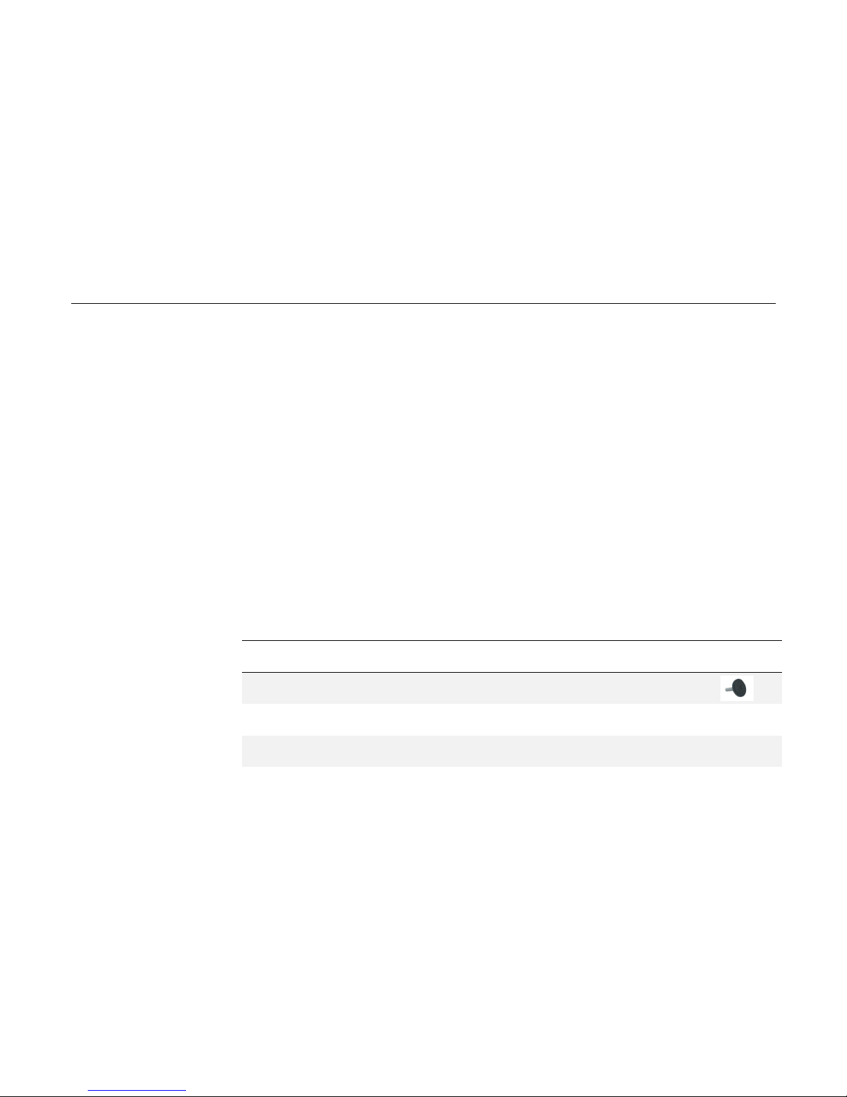
5.2Package information and system configuration list
The cabinet and battery are packaged separately with cartons, the components are taken along with the cabinet or battery package, before installation, installer
should read the system configuration list.
No.
Item
Description
Qt
y
Purpose
Picture
1
Anchor bolt
4
Make a distance from cabinet to ground.
2
User Manual
1
System information and using method and Warranty
items.
\
3
Installation
Manual
1
System installation guidance
\
Page 11
B-Box Residential installation guidance
11/ 43
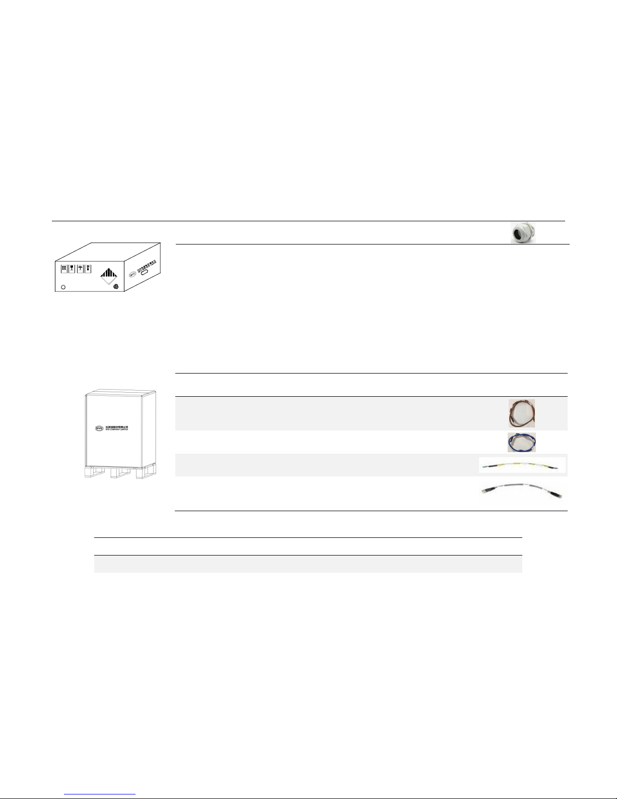
5.3 Configuration list
Type
B-Box Res 2.5
B-Box Res 5.0
B-Box Res 7.5
B-Box Res 10.0
B-Box cabinet
1 1 1
1
向上
易碎物品 堆码层数极限
怕雨
9
LITHIUM ION BATTERIES
UN3480
4G/Y50/S/16
CN/XXXXXX PI:XXX
n
u
9
4
Cable through
connector(IP55)
4
Cable through and waterproof
No.
Item
Description
Qty
Purpose
Picture
1
Positive cable 1 Battery P+ connection
2
Negative cable 1 Battery P- connection
3
GND
1
Connect
Battery grounded terminal
4
Communicatio
n cable
1
Battery RS485 port connection
Page 12

B-Box Residential installation guidance
12/ 43
B-Plus2.5
1 2 3 4 User manual
1 1 1 1 Positive cable
1 2 3 4 Negative cable
1 2 3
4
Communicate cable
1 2 3 4 Grounded cable
1 2 3
4
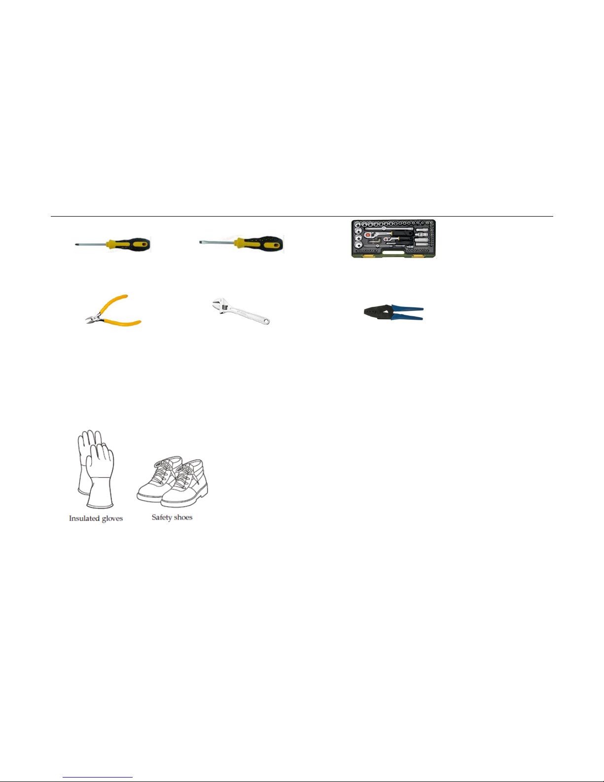
5.4 Installation Tools
Page 13
B-Box Residential installation guidance
13/ 43
Cross screwdriver
M3~M10
Flat tip screwdriver
M3~M6
Sockets spanner
Diagonal cutters
Adjustable wrench
Crimping pliers
5.5 Personal protective equipment
Page 14
B-Box Residential installation guidance
14/ 43
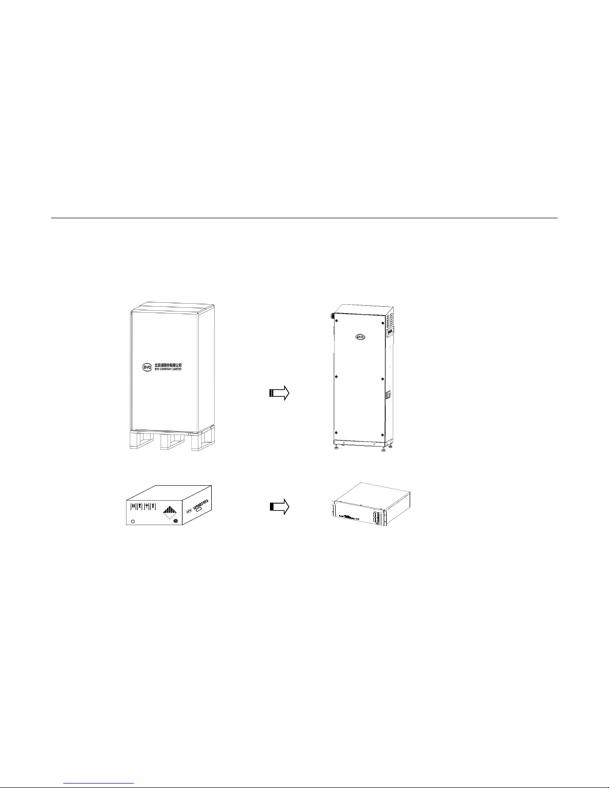
6Installation
6.1 Open the package
Tools: Knife
向上
易碎物品 堆码层数极限
怕雨
9
LITHIUM ION BATTERIES
UN3480
4G/Y50/S/16
CN/XXXXXX PI:XXX
n
u
9
Page 15
B-Box Residential installation guidance
15/ 43
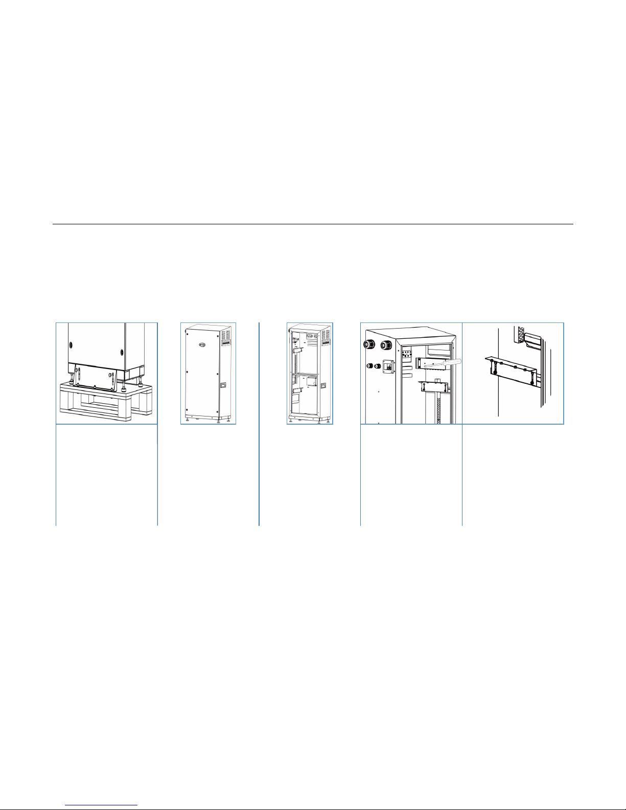
6.2 Disassemble thefixed seat& door and pallet
Tools:screwdriver
Remove fixed seat
Remove pallet
Take away the door Take away the air
circuit breakert.
Connect ground
wire
Page 16
B-Box Residential installation guidance
16/ 43
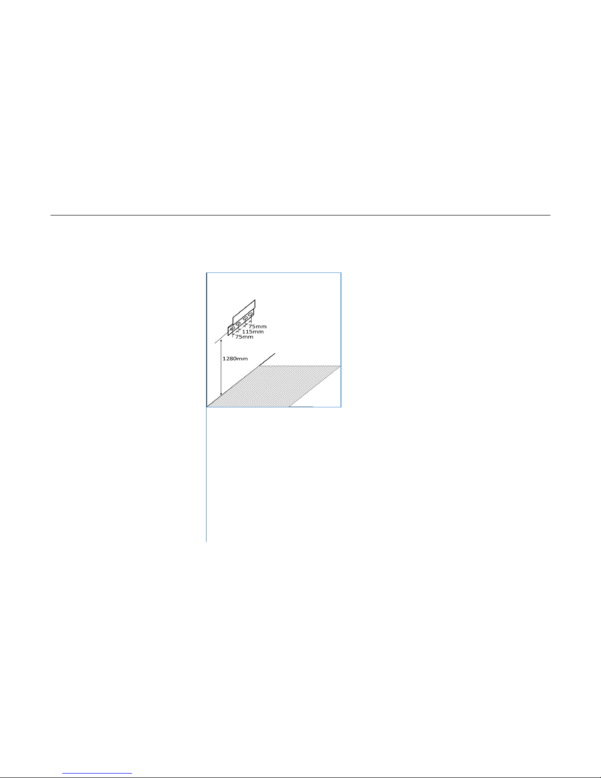
6.3Fix the frame on the wall, then fix the cabinet with the fixing frame
Tools:screwdriver
Fix the frame on the wall
Fixing.
Page 17
B-Box Residential installation guidance
17/ 43
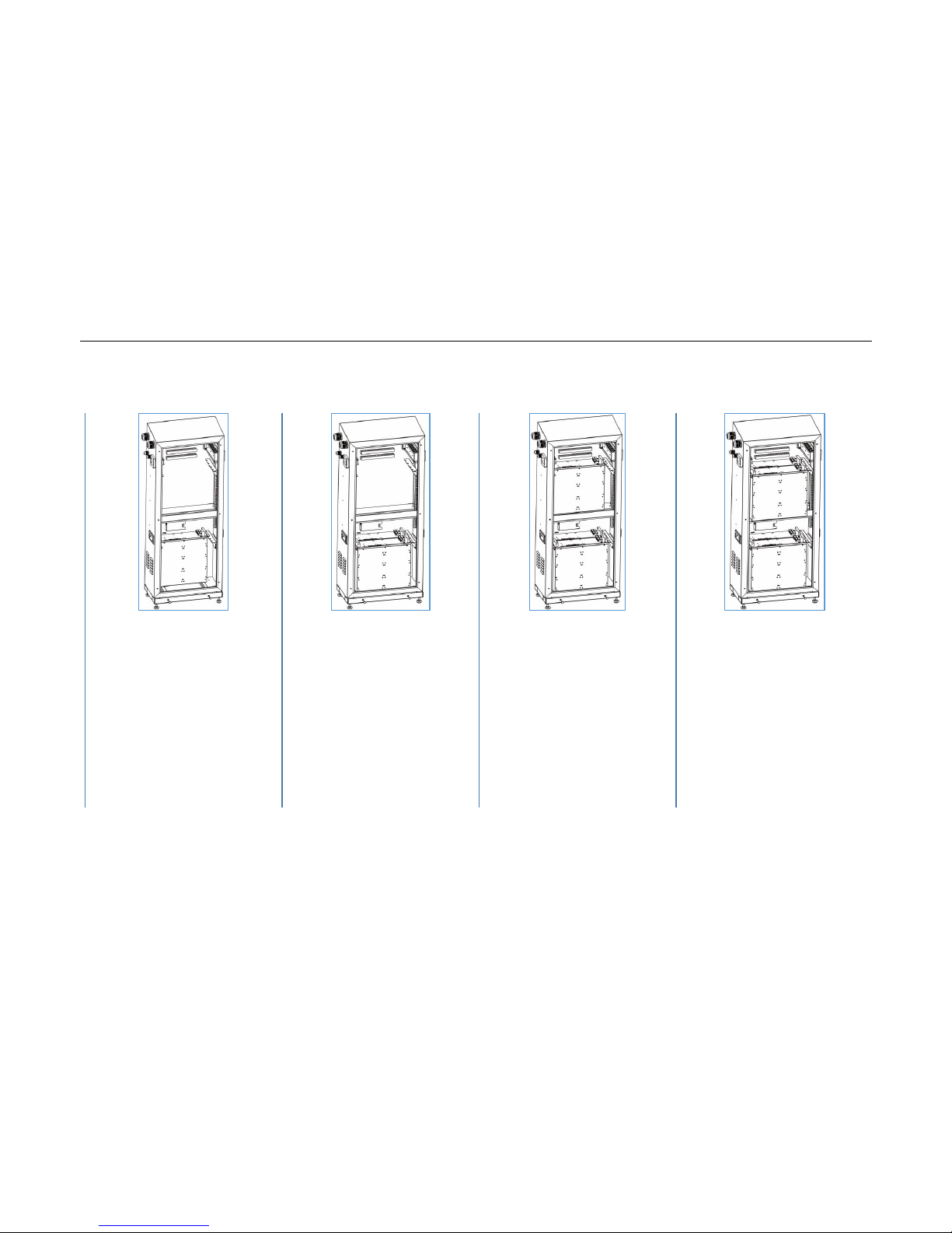
6.4Battery installation
Tools: Cross screwdriver;Sockets spanner
Put the first battery into
the cabinet.
Correct position is inside
the bottom layer,close to
back panel.
Put the second battery
into the cabinet.
Correct position is inside
the bottom layer,close to
front panel.
Put the third battery into
the cabinet.
Correct position is inside
the top layer,close to
back panel.
Put the fourth battery
into the cabinet.
Correct position is inside
the top layer,close to
front panel.
Fix all batteries with
screws.
Page 18
B-Box Residential installation guidance
18/ 43
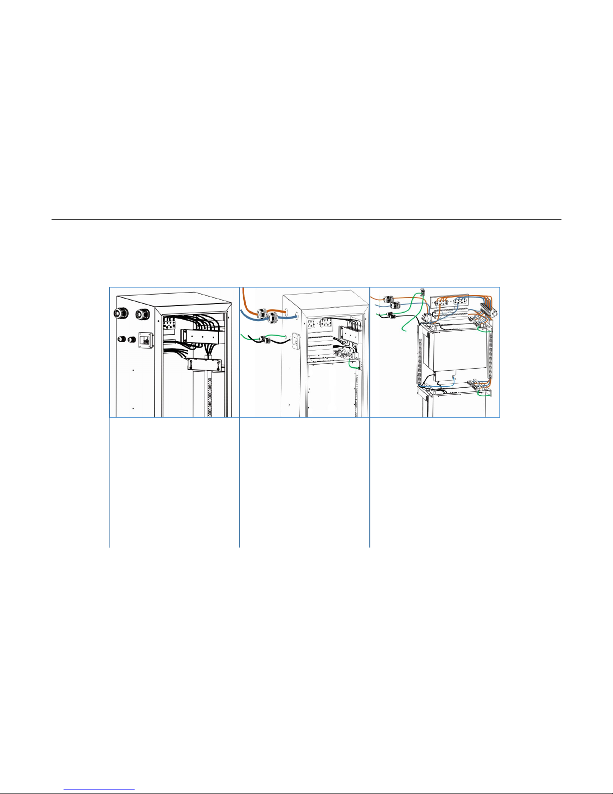
6.5Connect cables with battery
Tools: Cross screw driver Fixed torque: 20±2kgf.cm
Attention: The battery can only in parallel connection, do not connect batteries in series. Do not short connect, reverse polarity connect.
Fix the air circuit
breakert.Remark:Tube
type terminal stripe side
toward the positive
corresponding rack
(lateral) circuit breaker
Fix the cable through
connector
Connect the Positive
cable to P+ terminal
Connect the Negative
cable to P- terminal
Connect the grounded
cable to GND terminal
Connect communication
cable between BMU and
Inverter.
Page 19
B-Box Residential installation guidance
19/ 43
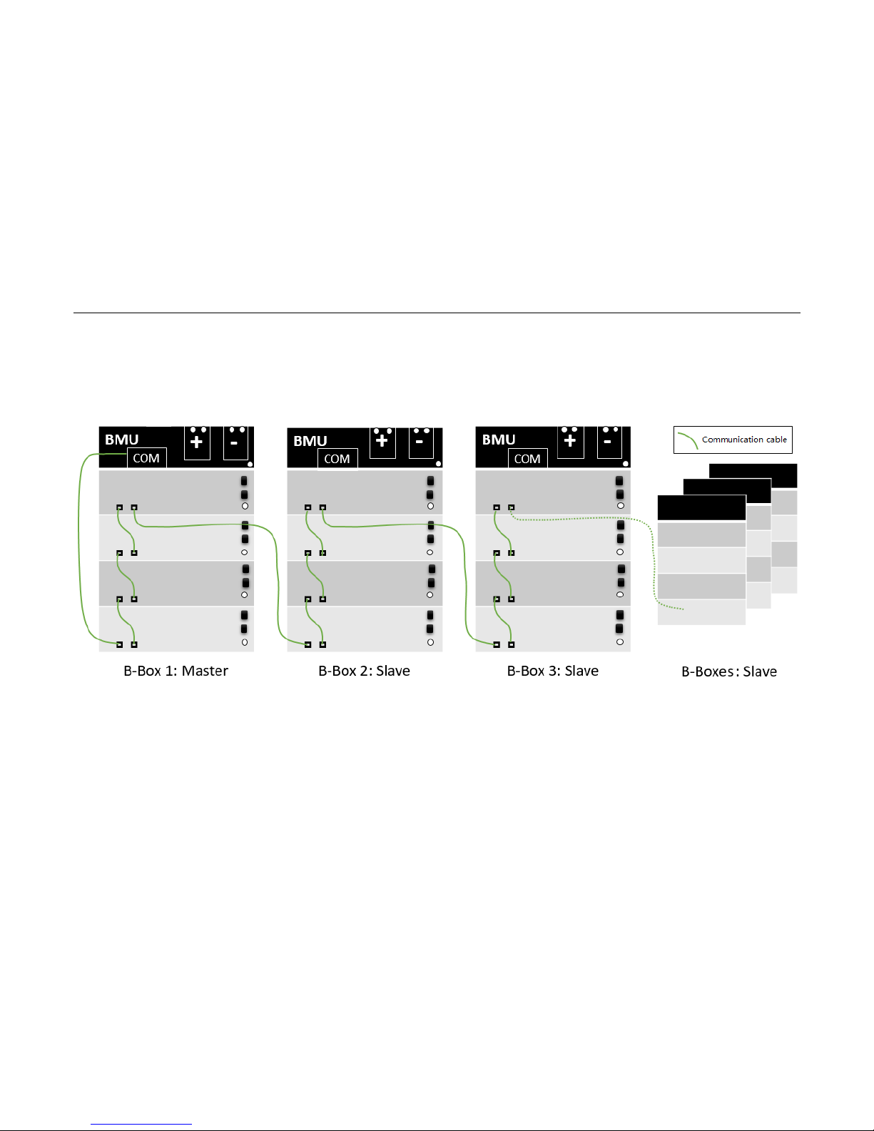
7Parallel connection between multi B-Box
7.1Communication cable connection drawing
Page 20
B-Box Residential installation guidance
20/ 43
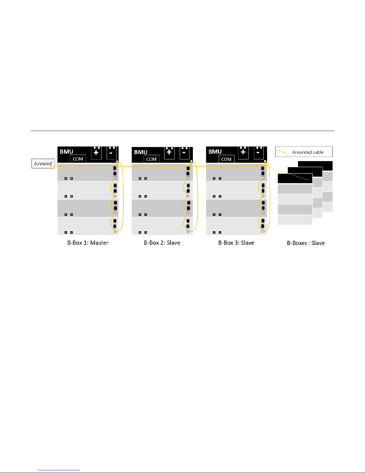
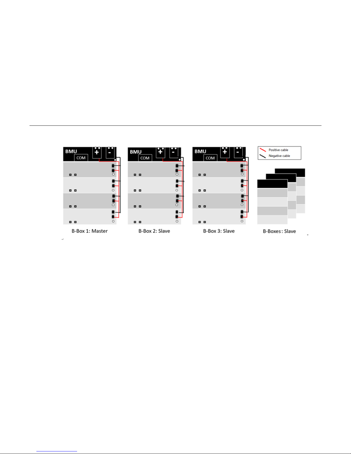
7.2Grounded cable connection between several B-Box
Page 21
B-Box Residential installation guidance
21/ 43
7.3Power cable connection between several B-Box
Page 22
B-Box Residential installation guidance
22/ 43
8Battery address set up
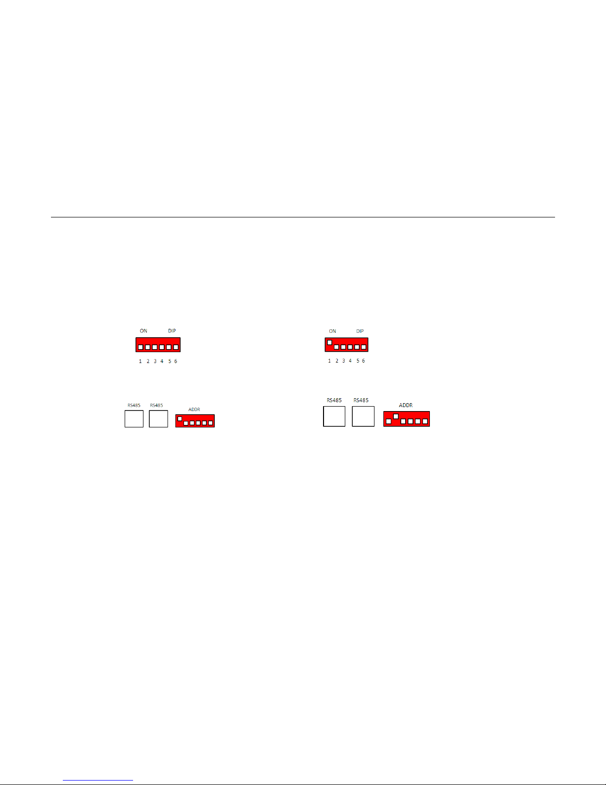
8.1“ADDR” switch introduction
Function: Communicate between battery and BMU, BMU will communication with external equipment when using CAN communication.
Each DIP switch definition:
There are 6 bit switches, keep the switch on down side means”0”, turn up the switch to “ON” means “1”.
Address: 000000 Address: 100000
For example: when two battery in using“ADDR” setting:
No.1 battery address: 100000 No.2 battery address: 010000
Address setting please according to the configuration list in next page.
Notice: Make sure of the highest address of B-Plus2.5 connect to BMU.
Page 23

B-Box Residential installation guidance
23/ 43
8.2 Battery address setting list (from 1~32 batteries)
Battery No.
Address
Battery No.
Address
1
100000
17
100010
2
010000
18
010010
3
110000
19
110010
4
001000
20
001010
5
101000
21
101010
6
011000
22
011010
7
111000
23
111010
8
000100
24
000110
9
100100
25
100110
10
010100
26
010110
11
110100
27
110110
12
001100
28
001110
13
101100
29
101110
14
011100
30
011110
15
111100
31
111110
16
000010
32
000001
Page 24
B-Box Residential installation guidance
24/ 43
9Connect to inverter
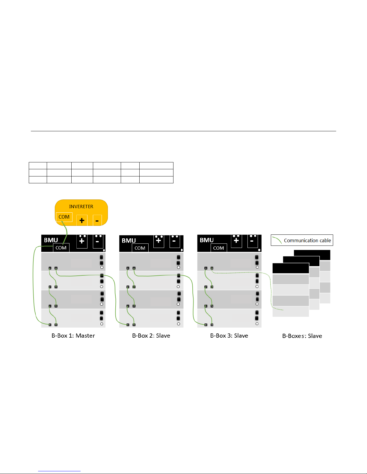
9.1 CAN cable connection
RJ45 PIN define
B-Box
SMA
GOODWE
SOLAX
VICTRON
CAN H
4 4 4 1 7
CAN L
5 5 5 2 8
When installer do “CAN” ports connections between B-Box and inverter, please refer to below drawing.
Batt 21
Batt 22
Batt 23
Batt 24
Batt 25
Batt 26
Batt 27
Batt28
Batt 29
Batt 30
Batt31
Batt 32
Page 25
B-Box Residential installation guidance
25/ 43
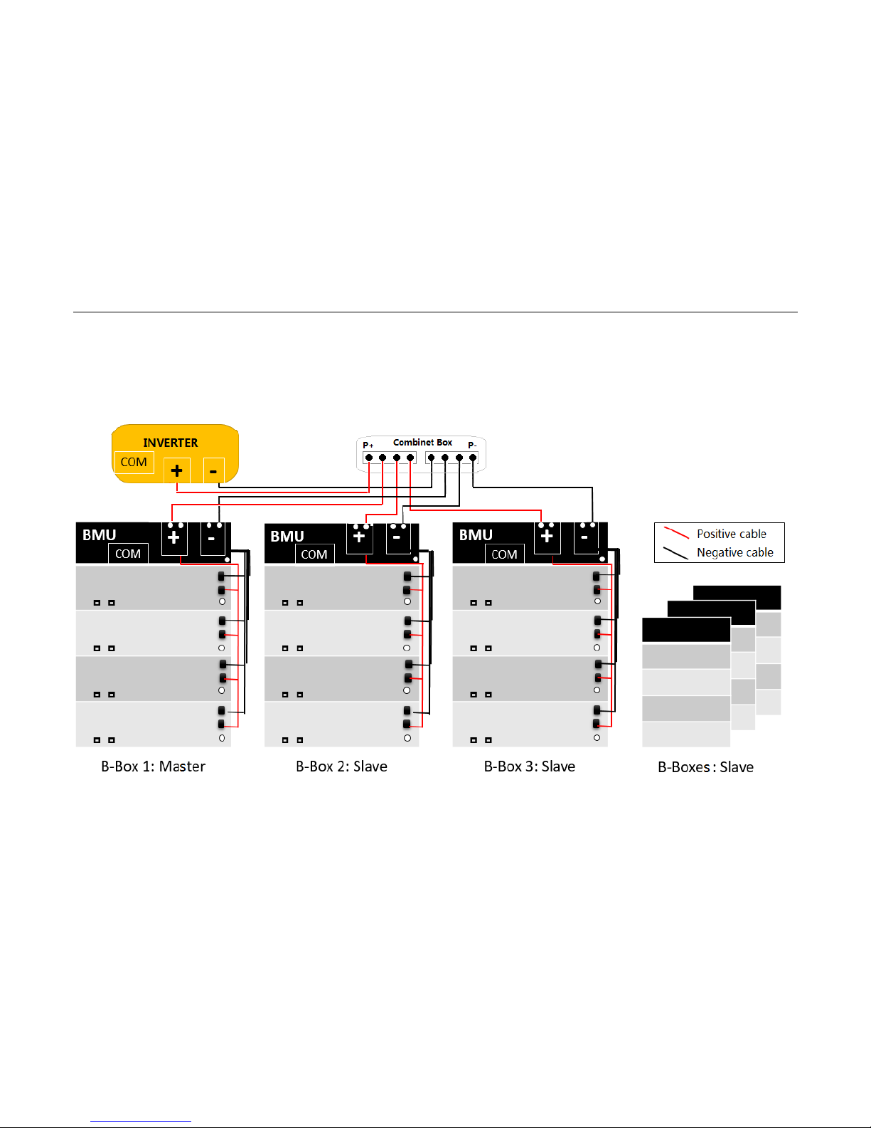
9.2 Power cable connection
Tools: Cross screwdriver, fixed torque: 25±2.5Nm
Remark: Each rack is negative line need to use the belt, and between each cabinet and inverter line length is the same. Be careful not to reverse connection.
Page 26

B-Box Residential installation guidance
26/ 43
10Start system
Notice: Before activity the system, please inspection according below items:
Confirm all the batteries are powered OFF.
Confirm all power cables are connected correctly and reliably.
Confirm all communication cables are connected correctly and reliably.
10.1System activity procedures when B-Box connect to SMA Sunny Island
⑴
Start B-Box;
i. Turn the switch of main circuit breaker (QFB0) to “ON”.
ii. Turn the switch of battery breaker (QFB1、QFB2、QFB3、QFB4) to “ON”.
iii. Press the “ON/OFF” button on front panel of B-Plus 2.5;
Tips: Press “ON/OFF” button one second can start B-Plus, According to the number of inverters in the following table, as far as possible within 8
seconds of button to activate the batteries.
Inverter
:1~2PCS
Inverter
:3~4PCS
Inverter
:5~7PCS
Inverter
:8~9PCS
The amount of battery
1 2 3
4
Once start, the LED lights of B-Plus 2.5 will be in different status according battery status as below:
LED status when normal start
Item
LED
Status
1
Run
Green
2
SOC
More than one is green.
Slow blink is charging and Fast blink is discharging.
The flash in order
means no
communication.
3
ERROR
OFF
4
Alarm
OFF
Page 27

B-Box Residential installation guidance
27/ 43
Status(display interval 2S)
Definition
LED(BMU)
Blinks 1 time
Inverter not connected
Blinks 2 time
Battery not connected
Blinks 3 time
Battery disconnect
Blinks 4 time
Battery failure
Remark:
Slow blink: Indicator light is on and off every 1s (0.5Hz).
Fast blink: indicator light is on and off every 0.25s (2Hz).
SOC status and indicate
Item
Status
Indicate
1
Four lights are all normally on
Capacity is 100%-75% (including)
2
The last three lights are normally on
Capacity is 74%-50% (including)
3
The last two lights are normally on
Capacity is 49%-25% (including)
4
The last one light is normally on
Capacity is 24%-1% (including)
⑵
Switching on the Sunny Island;
Procedure:
• For systems with one Sunny Island, press the "On" button on the Sunny Island.
☑
The inverter LED on each Sunny Island inverter is glowing orange and the Sunny Island inverters are in standby.
⑶
Start inverter;
Procedure:
Page 28

B-Box Residential installation guidance
28/ 43
• Press the start-stop button on the Sunny Island and hold it until an acoustic signal sounds. Or Press and hold the button on the Sunny Remote
Control until an acoustic signal sounds. ☑The inverter LED on each Sunny Island is glowing green.
⑷
Set up battery parameters on SRC of inverter;
Please refer to the “Battery Parameter setting” t able in Appendix1.
Remark: If the battery capacity is greater than or equal to 200AH, according to the Box10.0 parameter settings
⑸
System running.
Page 29

B-Box Residential installation guidance
29/ 43
10.2 System activity procedures when B-Box connect to GOODWE inverter
⑴
Open the GOODWE APP and open the home page;
⑵
Start B-Box;
i. Turn the switch of main circuit breaker(QFB0) to “ON”.
ii. Turn the switch of battery breaker (QFB1、QFB2、QFB3、QFB4) to “ON”.
iii. Press the “ON/OFF” button on front panel of B -Plus 2.5;
Tips: Press “ON/OFF” button one second can start B-Plus;
Once start, the LED lights of B-Plus 2.5 will be in different status according battery status as below:
LED status when normal start
Item
LED
Status
1
Run
Green
2
SOC
More than one is green.
Slow blink is charging and Fast blink is discharging.
The flash in order
means no
communication.
3
ERROR
OFF 4 Alarm
OFF
Status(display interval 2S)
Definition
LED(BMU)
Blinks 1 time
Inverter not connected
Blinks 2 time
Battery not connected
Blinks 3 time
Battery disconnect
Blinks 4 time
Battery failure
Remark:
Slow blink: Indicator light is on and off every 1s (0.5Hz).
Fast blink: indicator light is on and off every 0.25s (2HZ)
Page 30

B-Box Residential installation guidance
30/ 43
SOC status and indicate
Item
Status
Indicate
1
Four lights are all normally on
Capacity is 100%-75% (including)
2
The last three lights are normally on
Capacity is 74%-50% (including)
3
The last two lights are normally on
Capacity is 49%-25% (including)
4
The last one light is normally on
Capacity is 24%-1% (including)
⑶
Inverter activity;
⑷
Go to the home page of APP, enter into the Battery Setting page, select “BYD B-Box 2.5/5.0/7.5/10.0” battery, then select “NEXT” until the last page, at
last select “Start”.
Remark: If the installed capacity is greater than or equal to 10.0KWh, the App product model is chosen as "BYD B-Box 10"
(5)System running;
Page 31

B-Box Residential installation guidance
31/ 43
10.3 System activity procedures when B-Box connect to Victron inverter
⑴
Inverter start;
⑵
Set the battery DOD at a minimum of 5% on-grid; Set the battery DOD at a minimum of 10% off-grid.
⑶
Start B-Box;
i. Turn the switch of main circuit breaker (QFB0) to “ON”.
ii. Turn the switch of battery breaker (QFB1、QFB2、QFB3、QFB4) to “ON”.
iii. Press the “ON/OFF” button on front panel of B -Plus 2.5;
Tips: Press “ON/OFF” button one second can start B-Plus, According to the number of inverters in the following table, as far as possible within 8
seconds of button to activate the batteries.
Inverter
:1~2PCS
Inverter
:3~4PCS
Inverter
:5~7PCS
Inverter
:8~9PCS
The amount of battery
1 2 3
4
Once start, the LED lights of B-Plus 2.5 will be in different status according battery status as below:
LED status when normal start
Item
LED
Status
1
Run
Green
2
SOC
More than one is green.
Slow blink is charging and Fast blink is discharging.
The flash in order
means no
communication.
3
ERROR
OFF
4
Alarm
OFF
Page 32

B-Box Residential installation guidance
32/ 43
Status(display interval 2S)
Definition
LED(BMU)
Blinks 1 time
Inverter not connected
Blinks 2 time
Battery not connected
Blinks 3 time
Battery disconnect
Blinks 4 time
Battery failure
Remark:
Slow blink: Indicator light is on and off every 1s (0.5Hz).
Fast blink: indicator light is on and off every 0.25s (2HZ)
SOC status and indicate
Item
Status
Indicate
1
Four lights are all normally on
Capacity is 100%-75% (including)
2
The last three lights are normally on
Capacity is 74%-50% (including)
3
The last two lights are normally on
Capacity is 49%-25% (including)
4
The last one light is normally on
Capacity is 24%-1% (including)
⑷
System running.
Page 33

B-Box Residential installation guidance
33/ 43
10.4 System activity procedures when B-Box connect to Solax inverter
⑴
Open the GOODWE APP and open the home page;
⑵
Start B-Box;
i. Turn the switch of main circuit breaker(QFB0) to “ON”.
ii. Turn the switch of battery breaker (QFB1、QFB2、QFB3、QFB4) to “ON”.
iii. Press the “ON/OFF” button on front panel of B -Plus 2.5;
Tips: Press “ON/OFF” button one second can start B-Plus;
Once start, the LED lights of B-Plus 2.5 will be in different status according battery status as below:
LED status when normal start
Item
LED
Status
1
Run
Green
2
SOC
More than one is green.
Slow blink is charging and Fast blink is discharging.
The flash in order
means no
communication.
3
ERROR
OFF 4 Alarm
OFF
Status(display interval 2S)
Definition
LED(BMU)
Blinks 1 time
Inverter not connected
Blinks 2 time
Battery not connected
Blinks 3 time
Battery disconnect
Blinks 4 time
Battery failure
Remark:
Slow blink: Indicator light is on and off every 1s (0.5Hz).
Fast blink: indicator light is on and off every 0.25s (2HZ)
Page 34

B-Box Residential installation guidance
34/ 43
SOC status and indicate
Item
Status
Indicate
1
Four lights are all normally on
Capacity is 100%-75% (including)
2
The last three lights are normally on
Capacity is 74%-50% (including)
3
The last two lights are normally on
Capacity is 49%-25% (including)
4
The last one light is normally on
Capacity is 24%-1% (including)
⑶
Inverter activity;
⑷
Go to the home page of APP, and enter into Charger Setting page, select “Battery Type Lithium”, then select “Min Capacity” s etting 20%, at last select
“Battery awaken”.Choosing”YES”. Complete battery parameter settings.
(5)System running;
Page 35

B-Box Residential installation guidance
35/ 43
11Stop system
Notice: Before stop the system, please power off inverter first, then power off battery refer to below items:
i. Power off the devices which connect with batteries: Inverter&MPPT, etc.
ii. Turn the switch of main circuit breaker(QFB0) to“ OFF”
iii. Turn the switch of battery breaker(QFB1、QFB2、QFB3、QFB4) to “OFF”.
iv. Power off all batteries.
After stop the system, please check refer to below items:
Confirm all the batteries are powered OFF.
All the LED are OFF.
Inverter had powered off.
Page 36

B-Box Residential installation guidance
36/ 43
Appendix 1
SMA charger min capacity
Parameter setup for B-Box2.5
Charging the battery Usage through battery backup system without increased self-consumption
Parameters
Setup value
003.07Batt Typ
Li Lon_Ext-BMS
003.10Batt Cpynom
50
262.01ProtResSOC
3
262.02BatResSOC
10
Charging the battery usage through battery backup system with increased self-consumption
Parameters
Setup value
003.07Batt Typ
Li Lon_Ext-BMS
003.10Batt Cpynom
50
261.01SlfCsmplncEna
Enable
261.03Saisonenable
Yes
262.01ProtResSOC
3
262.02BatResSOC
6
262.03BUResSOC
0
262.04PVResSOC
8
262.05MinSlfCsmpSOC
75
Charging the battery usage through system for increased self-consumption without a battery backup grid
Parameters
Setup value
003.07Batt Typ
Li Lon_Ext-BMS
003.10Batt Cpynom
50
261.01SlfCsmplncEna
Enable
261.03Saisonenable
Yes
262.01ProtResSOC
3
262.02BatResSOC
6
Page 37

B-Box Residential installation guidance
37/ 43
262.04PVResSOC
8
262.03BUResSOC
0
262.05MinSlfCsmpSOC
75
Parameter setup for B-Box 5.0
Charging the battery Usage through battery backup system without increased self-consumption
Parameters
Setup value
003.07Batt Typ
Li Lon_Ext-BMS
003.10Batt Cpynom
100
262.01ProtResSOC
3
262.02BatResSOC
7
Charging the battery usage through battery backup system with increased self-consumption
Parameters
Setup value
003.07Batt Typ
Li Lon_Ext-BMS
003.10Batt Cpynom
100
261.01SlfCsmplncEna
Enable
261.03Saisonenable
Yes
262.01ProtResSOC
3
262.02BatResSOC
4
262.03BUResSOC
0
262.04PVResSOC
6
262.05MinSlfCsmpSOC
80
Charging the battery usage through system for increased self-consumption without a battery backup grid
Parameters
Setup value
003.07Batt Typ
Li Lon_Ext-BMS
003.10Batt Cpynom
100
261.01SlfCsmplncEna
Enable
261.03Saisonenable
Yes
262.01ProtResSOC
3
262.02BatResSOC
4
Page 38

B-Box Residential installation guidance
38/ 43
262.04PVResSOC
6
262.03BUResSOC
0
262.05MinSlfCsmpSOC
80
Parameter setup for B-Box7.5
Charging the battery Usage through battery backup system without increased self-consumption
Parameters
Setup value
003.07Batt Typ
Li Lon_Ext-BMS
003.10Batt Cpynom
150
262.01ProtResSOC
3
262.02BatResSOC
6
Charging the battery usage through battery backup system with increased self-consumption
Parameters
Setup value
003.07Batt Typ
Li Lon_Ext-BMS
003.10Batt Cpynom
150
261.01SlfCsmplncEna
Enable
261.03Saisonenable
Yes
262.01ProtResSOC
3
262.02BatResSOC
4
262.03BUResSOC
0
262.04PVResSOC
4
262.05MinSlfCsmpSOC
85
Charging the battery usage through system for increased self-consumption without a battery backup grid
Parameters
Setup value
003.07Batt Typ
Li Lon_Ext-BMS
003.10Batt Cpynom
150
261.01SlfCsmplncEna
Enable
261.03Saisonenable
Yes
262.01ProtResSOC
3
262.02BatResSOC
4
Page 39

B-Box Residential installation guidance
39/ 43
262.04PVResSOC
4
262.03BUResSOC
0
262.05MinSlfCsmpSOC
85
Parameter setup for B-Box10.0
Charging the battery Usage through battery backup system without increased self-consumption
Parameters
Setup value
003.07Batt Typ
Li Lon_Ext-BMS
003.10Batt Cpynom
200
262.01ProtResSOC
3
262.02BatResSOC
6
Charging the battery usage through battery backup system with increased self-consumption
Parameters
Setup value
003.07Batt Typ
Li Lon_Ext-BMS
003.10Batt Cpynom
200
261.01SlfCsmplncEna
Enable
261.03Saisonenable
Yes
262.01ProtResSOC
3
262.02BatResSOC
4
262.03BUResSOC
0
262.04PVResSOC
4
262.05MinSlfCsmpSOC
85
Charging the battery usage through system for increased self-consumption without a battery backup grid
Parameters
Setup value
003.07Batt Typ
Li Lon_Ext-BMS
003.10Batt Cpynom
200
261.01SlfCsmplncEna
Enable
261.03Saisonenable
Yes
262.01ProtResSOC
3
262.02BatResSOC
4
Page 40
B-Box Residential installation guidance
40/ 43
262.04PVResSOC
4
262.03BUResSOC
0
262.05MinSlfCsmpSOC
85
Parameter setup for B-Box in
off-grid
Protection for the Battery
Parameters
Recommended Value
223.05 BatPro1Soc
12%
223.06 BatPro2Soc
12%
223.07 BatPro3Soc
3%
Gen Autostart Control
Parameters
Recommended Value
235.03 GnSocTm1Str
17%
235.04 GnSocTm1Stp
35%
Parameter setup for B-Box7.5
Three-phase
Charging the battery Usage through battery backup system without increased self-consumption
Parameters
Setup value
003.07Batt Typ
Li Lon_Ext-BMS
003.10Batt Cpynom
150
262.01ProtResSOC
3
262.02BatResSOC
10
Charging the battery usage through battery backup system with increased self-consumption
Page 41

B-Box Residential installation guidance
41/ 43
Parameters
Setup value
003.07Batt Typ
Li Lon_Ext-BMS
003.10Batt Cpynom
150
261.01SlfCsmplncEna
Enable
261.03Saisonenable
Yes
262.01ProtResSOC
3
262.02BatResSOC
6
262.03BUResSOC
0
262.04PVResSOC
8
262.05MinSlfCsmpSOC
75
Charging the battery usage through system for increased self-consumption without a battery backup grid
Parameters
Setup value
003.07Batt Typ
Li Lon_Ext-BMS
003.10Batt Cpynom
150
261.01SlfCsmplncEna
Enable
261.03Saisonenable
Yes
262.01ProtResSOC
3
262.02BatResSOC
6
262.04PVResSOC
8
262.03BUResSOC
0
262.05MinSlfCsmpSOC
75
Parameter setup for B-Box10.0
Charging the battery Usage through battery backup system without increased self-consumption
Parameters
Setup value
003.07Batt Typ
Li Lon_Ext-BMS
003.10Batt Cpynom
200
262.01ProtResSOC
3
262.02BatResSOC
10
Charging the battery usage through battery backup system with increased self-consumption
Page 42

B-Box Residential installation guidance
42/ 43
Parameters
Setup value
003.07Batt Typ
Li Lon_Ext-BMS
003.10Batt Cpynom
200
261.01SlfCsmplncEna
Enable
261.03Saisonenable
Yes
262.01ProtResSOC
3
262.02BatResSOC
6
262.03BUResSOC
0
262.04PVResSOC
8
262.05MinSlfCsmpSOC
75
Charging the battery usage through system for increased self-consumption without a battery backup grid
Parameters
Setup value
003.07Batt Typ
Li Lon_Ext-BMS
003.10Batt Cpynom
200
261.01SlfCsmplncEna
Enable
261.03Saisonenable
Yes
262.01ProtResSOC
3
262.02BatResSOC
6
262.04PVResSOC
8
262.03BUResSOC
0
262.05MinSlfCsmpSOC
75
Appendix 2
Solax charger min capacity
Product
Min capacity
B-Box 2.5
20%
B-Box 5.0
15%
Page 43
B-Box Residential installation guidance
43/ 43
B-Box 7.5
15%
B-Box 10.0
10%
B-Box 12.8
10%
 Loading...