

BYD Battery-Box HV, Battery-Box H 5.1, Battery-Box H 7.7, Battery-Box H 6.4, Battery-Box H 9.0 Quick Reference Manual
...Page 1
BYD Battery-Box HV
QUICK REFERENCE GUIDE
Valid for Battery-Box H 5.1/6.4/7.7/9.0/10.2/11.5
Target Group
Skilled personnel recognized
This manual and the tasks and procedures described herein are intended for use by skilled workers only.
A skilled worker is defined as a trained and qualified electrician or installer who has all of the following skills and expenence:
• Knowledge of the functional principles and operation of on-grid systems.
• Knowledge of the dangers and risks associated with installing and using electrical devices and acceptable mitigation methods.
• Knowledge of the installation of electrical devices.
• Knowledge of and adherence to this manual and all safety precautions and best oractices.
• In order to ensure the normal operation of Battery-Box, please be sure to update the firmware to the latest version and finish the configuration on
Battery-Box webpage in accordance with this document.
• The system switch must be off before installing.
• Please make sure the system switch is off in case of the system not working, and it would be better to repair it again within one week, avoiding
overdischarge or other problems happen.
• Please do not stack up batteries without protective package when storing or handling batteries, unless in the case of installation.
• Please read the quick reference guide and installation manual carefully before installation.
• Please download and view the installation manual on this website:
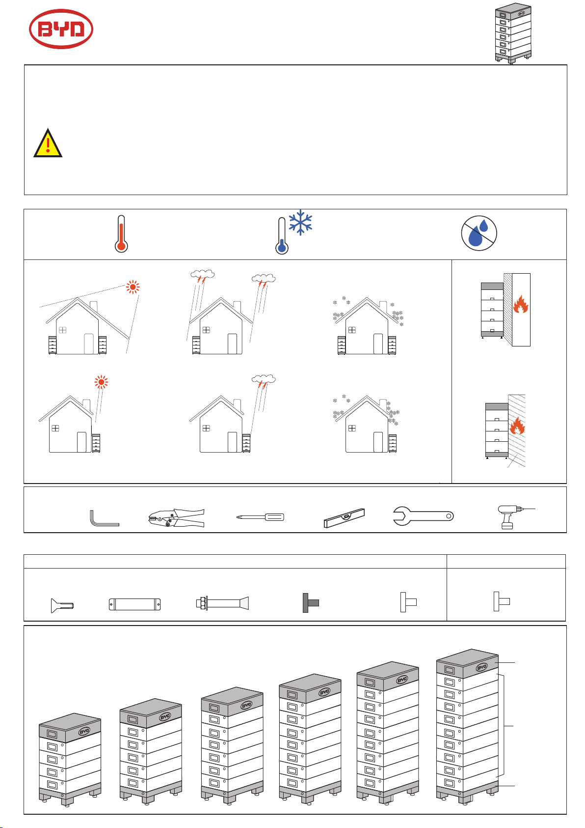
Installation environment requirements
V 5
www.eft-systems.de(Support->Downloads)
Tools
Max.
+50℃
Min.
-10℃
RH.
+5%~+95%
NO
Flammable material or
YES YES
YES
gas near the installation
NO
Direct sunlight
NO NO
Allen key Wire clamp Phillips screwdriver levelling instrument open-ended wrench churn drill
Direct rain fall
NO
Snow
accumulation
Flammable wall
Packing list
Packing of BCU+BASE
①M4×3
② Wall-mounted ×1
③ Expansion bolt M6×2
④ Sealing plug black ×3 ⑤ Sealing plug white ×3
Overall structure
Please refer to the BYD minimum Configuration List and to the inverter information
regarding the possible module configuration (n) with different Inverters.
n=6, 7.7KWh
n=5, 6.4KWh
n=4, 5.1KWh
n=7, 9.0KWh
n=8, 10.2KWh
Packing of B-Plus H 1.28
⑥
Sealing plug white ×2
n=9, 11.5KWh
BCU
B-Plus H 1.28
Base
Page 2
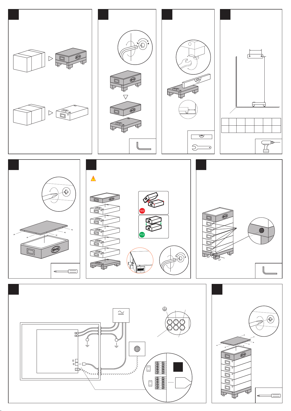
Unpack Balance
Separate base
2.
3.1.
and BCU
4.
Install wall-mounted
BCU + Base
B-Plus H 1.28
D
n
D=52mm~60mm
Open the cover of BCU Install Battery and BCU Lock sealing plug
5.
6.
1.Before installing BCU, make sure the
system switch is switch off.
2.For better installation, for each battery installed,
lock it tightly and reload the next battery.
7.
4
515
h
mm
170
h
mm
5 6 7 8 9
635 755 875 995 1115
Avoid the collision between
connector and corners.
Vertical install to protect the
connector
8. 9.
Connect the cables
Connection sequence of BCU
1. Ground cable.
2. Negative cable
3. Positive cable.
4. Communication cable
5. network cable.
P+
P-
Inverter
P-P
+
COM
Internet
P+
P-
to inverter CANto router
install sealing plug
*
⑥
④
Install the cover
1. Lock diagonal screws.
2. Lock other
screws.
Must be connected to the common
Ground.(Not on inverter)
Ethernet cable
*
13.
Page 3
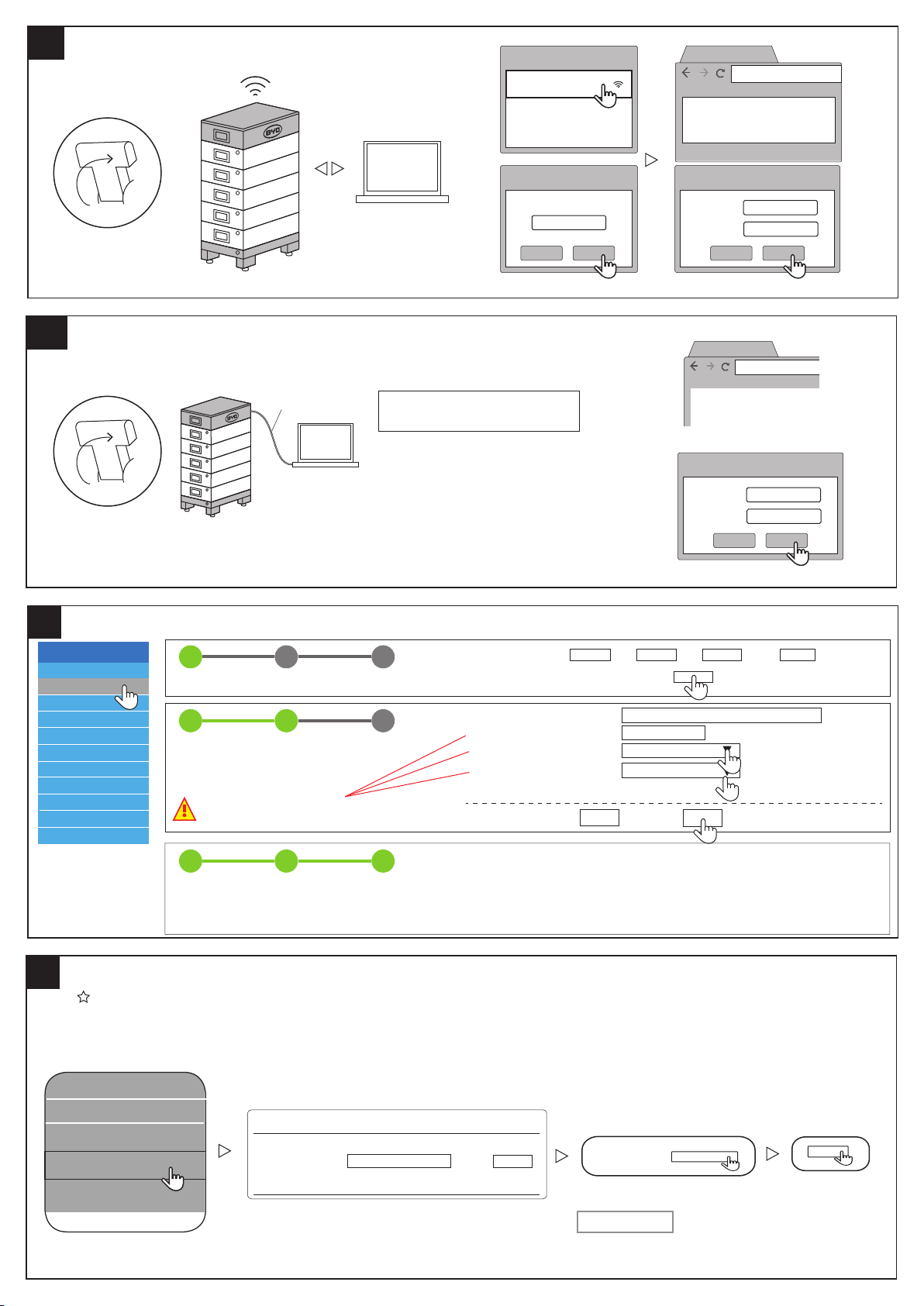
Connec through WIFI
SN:
Factory time:
Version:
SN:
Factory time:
wlan0
eth0:2
192.168.5.1
192.168.5.1
2017-7-13 21:12:12
BH02S0127RNN00
v1.023 S
2017-8-2 22:07:08
100321708-00
10a.
ON
WLAN
BYDxxx
network 1
network 2
192.168.5.1.
192.168.5.1
192.168.5.1.
192.168.5.1.
10b.
Connect through ethernet cable
ON
11.
Setup system information
network cable
BYDxxx
WLAN password
123456789
cancel login
①Connect the network cable
②Set your computer IP into a static IP
IP address:192.168.6.10
Subnet mask:255.255.255.0
Setting method reference computer system setting method
③
④
BYDxxx
Username
Password
cancel login
192.168.6.1
BYDxxx
Username
Password
cancel login
installer
byd@12345
192.168.6.1.
installer
byd@12345
Battery-Box HV
Privacy Policy
Installation
Home
Device Information
Installation Config
Statistics Information
Current Alarm
History Alarm
Run Data
Set Password
Update
Update the firmware
12.
Update to the latest firmware (according to inverter type). Download Firmware at: www.eft-systems.de (Downloads)
History Alarm
History Alarm
Run Data
Set Password
Update
1 32
STEP 1 STEP 2 FINISH & REBOOT
1 32
STEP 1 STEP 2 FINISH & REBOOT
This parameter is important.
If set up incorrectly, it can cause the system to fail to work.
1 32
STEP 1 STEP 2 FINISH & REBOOT
Please input the file :
Update
Search
Time and Date *
Hour : Min : Day : Month : Year :
Server IP Address *
Series Battery Conts *
Inverter *
Country *
Asterisk(*)Indicates required fields
Last
Reboot System…
Please wait about 50 seconds.
Upload
Please input file:
Next
bboxhserver.byd.com.cn
4/5/6/7/8/9
SMA
Next
Search
Upload
If there is any new version on the server, clicking UpdateCheck will update the syesem.
Page 4
13a.
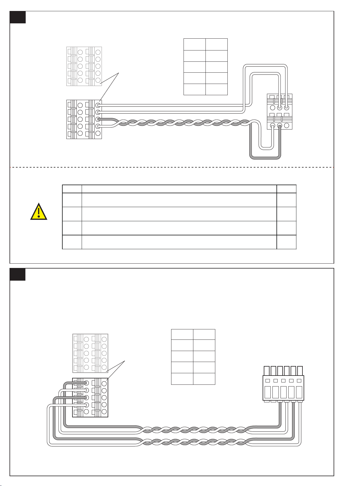
SMA Sunny Boy storage 2.5 / 3.7 / 5.0 / 6.0
Use a twisted-pair wire for CAN_H and CAN_L (PIN 6 and 8).
This is important for the stability of the CAN
Battery-Box
1
3
5
7
9
2
4
6
8
10
Choose any one
Battery-Box
pin
2
4
6
SBS
pin
B
C
E
1
3
5
7
9
2
4
6
8
10
Set Battery parameters in the SMA inverter:
No. SMA SBS Parameter
Battery-Areas of application-Lower Imt deep disch.Protect area prior shutdown
1
Battery-Nutzungsbereiche-Untere Grenze des Tiefenladenschutzbereichs vor Abschaltung
Battery-Areas of application-Minimum width of deep discharge protection area
2
Battery-Nutzungsbereiche-Minimale Breite des Tiefenladenschutzbereichs
Battery-Areas of application-Area width for c
3
Battery-Nutzungsbereiche-Breite des Bereichs zur Erhaltung des Batterieladezustands
Battery-Areas of application-Minimum width of own consumption area
4
Battery-Nutzungsbereiche-Minimale Breite des Tiefenladenschutzbereichs
8
ng battery sate of charge
onservi
D
A B C
SMA
Sunny Boy
Storage
D E F
2%
3%
3%
100%
13b.
SMA Sunny Boy Storage 2.5 software version ≥ SBS2.5-V2.04.23
KOSTAL PIKO BA Valid for PIKO 6.0 BA,PIKO 8.0 BA,PIKO 10 BA
Battery-Box
1
3
5
7
9
1
3
5
7
9
2
4
6
8
10
2
4
6
8
10
Choose any one
Battery-Box
pin pin
1
3
5
7
KOSTAL
3
4
5
6
KOSTAL PIKO
BA
RS485 - EM-
1 2 3 4 5 6
yp 4
T
KOSTAL PIKO BA software version ≥ Firmware:FW-B2.30
UI:UI-B6.44
Page 5
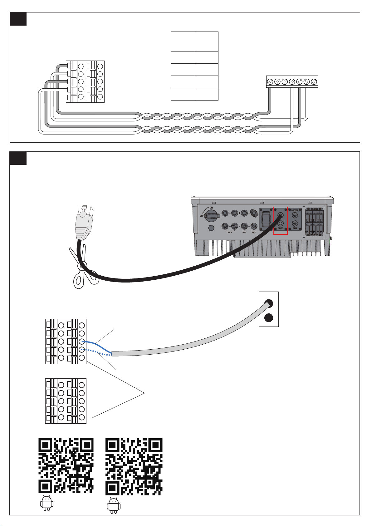
13C.
KOSTAL PLENTICORE plus
13d.
B-Box
pin
1
3
5
7
9
2
4
6
8
10
Goodwe ET Inverter
① Cut the BMS cable of the Goodwe ET (according to Goodwe Manual).
1
3
5
7
KPP
pin
1
6
5
4
KOSTAL
PLENTICORE
PLUS
1 2 3 4 5 6
Goodwe ET
BMS
Goodwe
② Connect the blue PIN to terminal block position 6 and the white-blue PIN to
terminal block position 8, according to the picture.
1
3
5
7
9
2
4
6
8
10
Blue
BMS
white-blue
1
3
5
7
9
③ Download the Goodwe App to setup the inverter. Please refer to the Goodwe installation manual.
2
4
6
8
10
Choose any one
ANDROD
ANDROD
Page 6
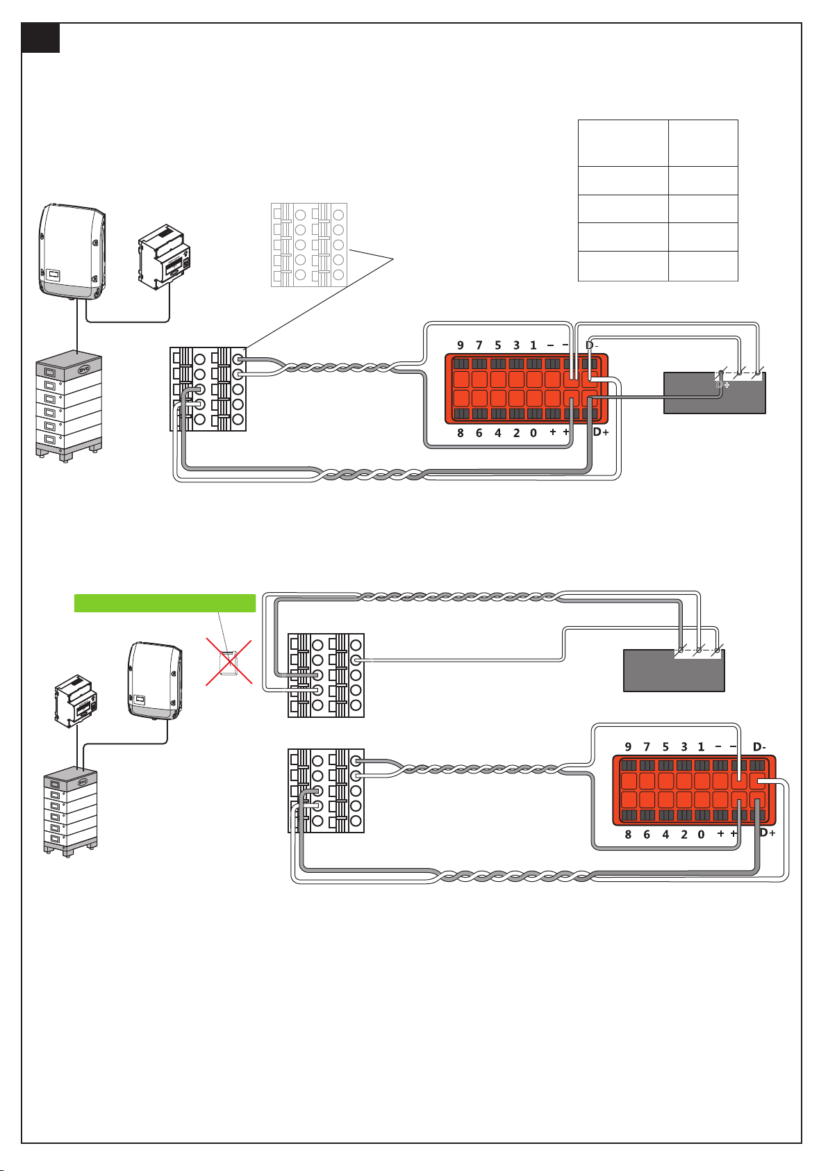
13e.
Fronius Symo Hybrid
Please refer to the inverter installation manual for detailed wiring.
1. When connecting the meter in the second connection mode, the jumper cap above the
JP2 in the BCU PCBA must be unplugged. If not unplugged, it is possible that the
Battery-Box and inverter will not be able to communicate properly.
2.Due to simplicity of installation, connection method 1 is recommended.
Connection method 1
Fronius
Smart Meter
Battery-Box
1
3
5
7
9
Battery-Box
Pin
2
2
4
6
8
10
Choose any one
4
5
7
Fronius
pin
+
-
D+
D-
Connection method 2
JP2 is in the BCU of Battery-Box
Fronius
Smart Meter
1
3
5
7
9
10
JP2
Remove JP2
2
4
-
D-
6
8
D+
Fronius Smart Meter
Fronius Symo Hybrid
Battery-Box
1
3
5
7
9
1
3
5
7
9
2
4
6
8
10
2
4
6
8
10
Fronius Smart Meter
D+ D-
-
Fronius Symo Hybrid
Page 7
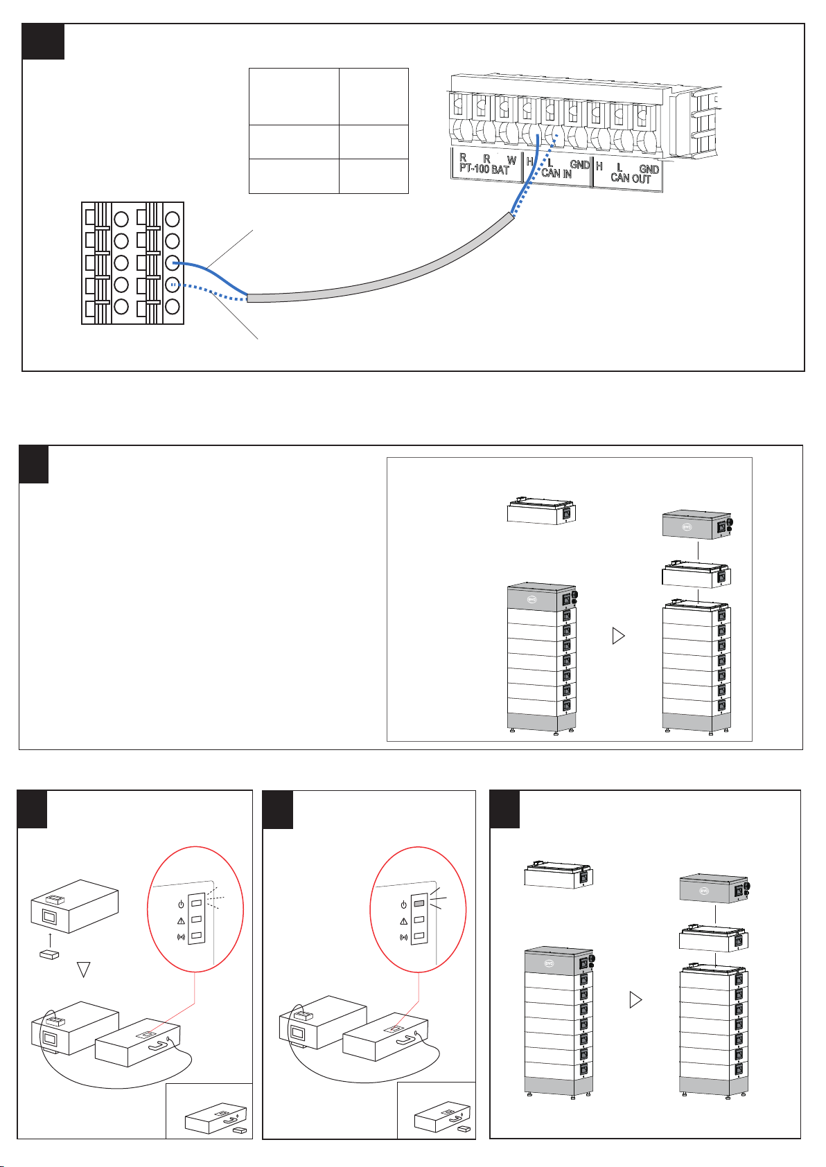
13F.
Ingeteam Ingecon Sun Storage 3TL and 6TL
Battery-Box
Pin
Ingeteam
J76
Ingeteam
pin
Battery-Box
10
2
4
6
8
Blue
1
3
5
7
9
white-blue
Battery-Box HIGH VOLTAGE EXTENSION
Without charger
Charge or discharge the original battery system so
14.
that its SOC becomes 30% to 40%, and add another
battery module. The actual SOC difference will be
automatically balanced in the next 2 weeks or so.
(Batterry-Box capacity may not be enough during this
time, this is normal)
6
8
CAN IN-H
CAN IN-L
Ethernet cable without the RJ45 terminals
15c.
SOC=30%-40%
New battery module
SOC=30%-40%
Home
With charger
Run Date
15a.
Set Password
Update
Charging = Green
LED blinking
15b.
SOC=100%
Original battery
system
100% = Green LED
constantly on
15c.
SOC=100%
SOC=100%
HV Charger
HV Charger
Page 8
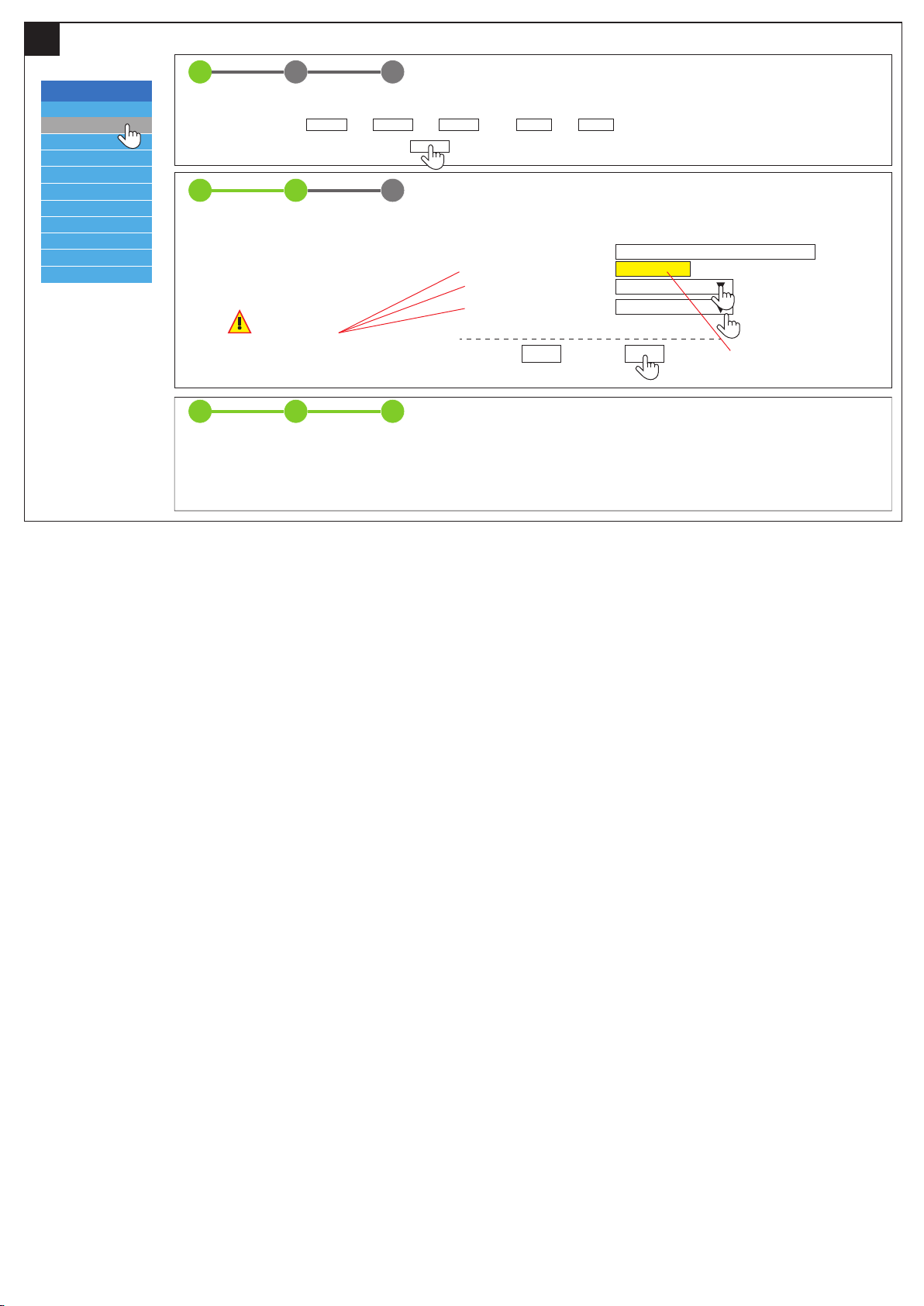
15d.
Battery-Box HV
Privacy Policy
Installation
Home
Device Information
Installation Config
Statistics Information
Current Alarm
History Alarm
Run Date
Set Password
Update
1 32
STEP 1 STEP 2 FINISH & REBOOT
Time and Date *
Hour : Min : Day : Month : Year :
Next
1 32
STEP 1 STEP 2 FINISH & REBOOT
Server IP Address *
Series Battery Conts *
Inverter *
Country *
These parameters is important.
Please make sure the correct configuration for these parameters,
otherwise the system might not work normally.
Asterisk(*)Indicates required fields
1 32
STEP 1 STEP 2 FINISH & REBOOT
Reboot System…
Please wait about 50 seconds.
Last
bboxhserver.byd.com.cn
n+m
SMA
Next
n=3-8 Modules
m=1-6 new Modules
Up to a maximum of 9
Diese Anleitung stellt eine verkürzte Aufbauhilfe dar, und ersetzt nicht die
original Anleitung der Battery-Box, erhältlich auf www.eft-systems.de
Installation darf nur von Fachleuten durchgeführt werden. Achtung
Hochvoltspeicher! Bei unsachgemäßer Handhabung kann Gefahr für Leib
und Leben entstehen. Für weitere Informationen oder Kontakt:
www.eft-systems.de
This manual is a shortened assistance for the installation of the
Battery-Box HV and does not replace the original manual, which can be
found on www.eft-systems.de The installation must be carried out by a
qualied expert. Attention, High Voltage Storage! Improper handling
can cause danger and damage.
 Loading...