


G2M CLASSIC | Rev. 2018.1.1
G2M Control Board
Installation and Operators Manual
Specifications:
Power Supply: Single-Phase 115-Volt or 220-Volt 50/60 Hz AC
Motor Power Consumption: Up to 550 Watts or 3/4 HP
Electric Lock Output: 12-Volt DC 1-Amp Maximum
Accessory Power Output: 24-Volt AC 1-Amp Maximum
Input Power Fuse: 2-Amp, 250-Volt; 5mm x 20mm Tubular Glass
Motor Power Fuses: 6-Amp, 250-Volt; 5mm x 20mm Tubular Glass
307.334.2865 www.byan.com
Fax: 307.334.2028 Toll Free: 800.223.2926
P.O. Box 1384 | 413 South Linden Street | Lusk, Wyoming 82225
BYAN
SYSTEMS INC.
Automatic Gate and Access Control Products

G2M CLASSIC | Rev. 2018.1.1
Table of Contents
PRODUCT WARNING ............................................................................................................................................. Page 3
G2M Board Description ...................................................................................................................................... Page 4
Terminal Information .......................................................................................................................................... Page 5
Power and Motor Run Terminal Table ................................................................................................................ Page 5
Commercial Power Hook-Up .............................................................................................................................. Page 5
Accessory Terminal Table ................................................................................................................................... Page 6
Accessory Hook-Up ............................................................................................................................................. Page 7
Timing Potentiometers ....................................................................................................................................... Page 8
S1 DIP Switches ................................................................................................................................................... Page 8
S2 DIP Switches ................................................................................................................................................... Page 8
12x10 Prewire Layout ......................................................................................................................................... Page 9
20x16 Prewire Layout ...................................................................................................................................... Page 10
24x20 Prewire Layouts ...................................................................................................................................... Page 11
24x20 Prewire Terminal Strip Guide ................................................................................................................ Page 12
Troubleshooting Guide ..................................................................................................................................... Page 13
T2M Leaf Delay Card ......................................................................................................................................... Page 14
FINAL SYSTEM WARNINGS .................................................................................................................................. Page 15
Byan Systems, Inc. Warranty Information ......................................................................................................... Page16
-2-

G2M CLASSIC | Rev. 2018.1.1
THIS PRODUCT SHOULD ONLY BE INSTALLED
AND / OR
MODIFIED BY QUALIFIED TECHNICAL PERSONNEL.
READ ALL OWNER’S MANUALS AND SAFETY INSTRUCTIONS
-3-

G2M CLASSIC | Rev. 2018.1.1
BYAN SYSTEMS G2M CONTROL BOARD
The G2M is a single phase, microprocessor controlled unit. It is capable of controlling up to two
¾-hp, 115-volt or 220-volt AC motors. Two different plug in accessory cards are available for the
G2M: a leaf delay card (which comes standard with every board), and a traffic light card (which
is available separately). There are three timing potentiometers as well as nine DIP switches
incorporated into the board to control different output functions.
-4-

G2M CLASSIC | Rev. 2018.1.1
Terminal Strips:
There are two sets of terminals on the G2M control board. The first terminal strip is the Power and Motor Run
Terminal Block, located on the left side of the board below the transformer. This is where the incoming
commercial power and the outgoing power to the operators are connected. This terminal strip is made up of
three terminal blocks: 1) In-coming Power; 2) Motor One; and 3) Motor Two.
Power and Motor Run Terminals
Terminal
Number Terminal Name / Description
Wire Colors
1
Commercial Power Input Neutral
115V White / 220V Black
2
Commercial Power Input Hot
115V Black / 220V Red
3
Motor One Close Directional
Black
4
Motor One Open Directional
Red
5
Motor One Common
White
6
Motor Two Close Directional
Black
7
Motor Two Open Directional
Red
8
Motor Two Common
White
Commercial Power Hook-Up*:
1. Hook up commercial power to Terminals 1 and 2 of the Power and Motor Run Terminal Strip.
2. Connect leads from the Motor No. 1 operator to Terminals 3, 4, and 5 of the Power and Motor Run Terminal
Strip.
3. Connect leads from the Motor No. 2 operator to Terminals 6, 7 and 8 of the Power and Motor Run Terminal
Strip.
4. Connect Motor Run Capacitors across each set of directional motor leads (between Terminals 3 and 4, and
Terminals 6 and 7).
-5-
115V White / 220V Black
115V Black / 220V Red
Capacitor
Capacitor
Black
Black
Red
Red
White
White
Motor 1
Motor 2
1
2
3
4
5
6
7
8

G2M CLASSIC | Rev. 2018.1.1
The second terminal strip is the Accessory Terminal Strip. This is where ALL of the accessories are connected to
the controller board. This terminal strip is located on the bottom right of the G2M Controller Board. This terminal
strip consists of two socketed blocks to allow you to unplug the connector as a whole without removing wires. The
drawings on Pages 10-12 are color-coded for ease in determining wiring connections for accessories.
Accessory Terminal Table
Terminal
Numbers
Terminal Name
Possible Uses
1 - 2
Alarm Output
These terminals allow the connection of a device to alert
the user that people safe has been activated.
3 - 4
24-Volt AC 1-Amp Output
Power for accessories such as radio receivers, loop
detectors, or anything requiring 24-Volt AC 1-Amp may
be connected here.
5 – 6
12-Volt DC 1-Amp Pulsed Electric
Lock Output
Magnetic or other types of lock release signals may be
connected here.
7 – 9
People Safe Alarm Reset Input
A button or other Normally Open contact may be
connected here to reset the People Safe alarm output
relay.
8
People Safe Input
Normally Closed People Safe devices such as sensing
edges are connected here.
9
Safety Common Input
Common wires for people and car safety devices are
connected here.
10
Car Safe Input
Normally Closed Car Safe devices such as loop detectors
and photo beams are connected here.
11
Limit Switch Common Input
If limit switches are required, the common wires would
be connected here.
12
Close Limit Switch Input
If limit switches are required, the close limit switch
would be connected here.
13
Open Limit Switch Input
If limit switches are required, the open limit switch
would be connected here.
14 – 15
Stop Input
A Normally Closed device used to stop the operators
such as a button may be connected here.
16
Control Function Common Input
This is where the common of devices used to open,
close, or reverse the gate would be connected.
17
Close Function Input
Devices only used to close the gate such as in-ground
loops, buttons, or photo beams are connected here.
18
Open Function Input
Devices only used to open the gate such as in-ground
loops, buttons, or radio receivers are connected here.
(Any Normally Open devices used to access the gate key
pads, card readers, etc.)
19
Reverse Function Input
Devices used to reverse the gates’ direction such as inground loops, buttons, or radio receivers are connected
here.
-6-

G2M CLASSIC | Rev. 2018.1.1
Accessory Hook-Ups*:
There are many accessories available that are compatible with the G2M that will give the end user different
options for safety, security, and system operations. Since it would be impossible to outline all possible
combinations, we will simply outline a few of the most common. Keep in mind; these instructions are specific to
the brand and model most commonly used by Byan Systems. Your accessories may differ from the ones listed
below. ALWAYS consult the Installation Instructions included with an accessory before connecting it to any
operating system.
Linear GRD_1 Radio Receiver:
1. Separate the four wires coming out of the bottom of the Receiver (1 Red, 1 Black, and 2 Gray).
2. Connect the black wire to Terminal 3 of the Accessory Terminal Strip.
3. Connect the red wire to Terminal 4 of the Accessory Terminal Strip.
4. Connect one of the gray wires to Terminal 16 of the Accessory Terminal Strip.
5. Connect the other gray wire to Terminal 18 of the Accessory Terminal Strip for open only or Terminal 19 for use as a
reversing device.
6. If an external antenna is required, locate the Bulk Head Connector supplied with the Receiver.
7. Drill one 3/8” hole in the enclosure where you would like to mount the antenna.
8. Install the Bulk Head Connector in the hole using the hardware included with the Receiver. Be sure to use thread
locking compound in the threads when installing the connector.
9. Connect the supplied coax between the Receiver and the Bulk Head Connector and attach the antenna to the
outside of the connector.
Mag-Lock Relay Using IDEC SH2B-05 Base w/RH2B-UDC12V Relay:
1. Connect Terminal 13 on the Relay Base to Terminal 5 of the Accessory Terminal Strip on the board.
2. Connect Terminal 14 on the Relay Base to Terminal 6 of the Accessory Terminal Strip on the board.
3. Connect Neutral or Ground from the Mag-Lock Transformer directly to the Mag-Lock.
4. Connect Hot from the Mag-Lock Transformer to Terminal 9 of the Relay Base.
5. Connect Terminal 1 on the Relay Base to the Mag-Lock.
Loop Detector Using IDEC SR3P-06 Base w/EDI LMA1500-120 Loop Detector:
1. Connect Terminals 7 and 8 to the in-ground loop leads.
2. Connect 120-Volt AC Neutral to Terminal 2 of the Detector Base.
3. Connect 120-Volt AC Hot to Terminal 1 of the Detector Base.
4. Connect desired signal wires from the Detector Base to the Accessory Terminal Strip of the G2M.
Shadow Using IDEC SH2B-05 Relay Base and RH2B-UAC110-120 Relay:
1. Connect Terminal 9 of the Relay Base to Terminal 5 of the Detector Base.
2. Connect Terminal 5 of the Detector Base to Terminal 9 of the Accessory Terminal Strip.
3. Connect Terminal 5 of the Relay Base to Terminal 10 of the Detector Base.
4. Connect Terminal 10 of the Detector Base to Terminal 10 of the Accessory Terminal Strip.
Safety:
1. Connect Terminal 5 of the Detector Base to Terminal 9 of the Accessory Terminal Strip.
2. Connect Terminal 10 of the Detector Base to Terminal 10 of the Accessory Terminal Strip.
Free Exit:
1. Connect Terminal 5 of the Detector Base to Terminal 16 of the Accessory Terminal Strip.
2. Connect Terminal 6 of the Detector Base to Terminal 18 of the Accessory Terminal Strip.
-7-

G2M CLASSIC | Rev. 2018.1.1
Characteristics:
Adjustable Timing Potentiometers:
Color
Description
Minimum Time
Maximum Time
Green
Automatic Closing Timer
1 Second
1 Minute 30 Seconds
Blue
Opening Timer
3 Seconds
30 Seconds *
Red
Closing Timer
3 Seconds
30 Seconds *
*With DIP Switch 1 on S2 turned on, the maximum open and close times are doubled to 1 Minute.
DIP SWITCHES:
Table S1
Number
Option Name
Option Description
1
Reversing Stroke
Function
When turned on, the operators will first close for 1 second
before opening.
2
Step-by-step Function
When turned on, each movement of the operators by any
reverse input will require an individual input (deactivates
automatic re-open function).
3
Automatic Closing
Function
When turned on, the operators will close by the time set
with the green timing potentiometer.
4
Reverse Button
Inoperative During
Opening
When turned on, any reverse input is deactivated during
the open cycle.
5
Closing Order by Car
Safety Contact
With DIP switch 3 off and 5 turned on, the operators will
close as soon as the car safety contacts are cleared.
6
*See Below
*See Below
7
Car Safety Contact
Operative During
Opening
When turned on, car safety contacts are active during the
open and close cycles. Input safety for vehicles only
works on closing movement unless Switch 7 is set ON.
*The function of DIP switch 6 is changed by the position of the jumper (JP1) located below the radio receiver card (J3).
Table S1a describes the function of DIP switch 6 and its relation to JP1.
Table S1a
JP1 Open
JP1 Closed
DIP Switch 6 ON
When power is applied to the board,
operators will automatically perform
a closing function.
The traffic light card will act as a
flashing light card (upper relay) and
a garage light card (lower relay).
DIP Switch 6 OFF
When power is applied to the board,
the operator will automatically
perform an opening function.
The traffic light card relays will act
as a green light (upper relay) and a
red light (lower relay).
Table S2
Number
Option Name
Option Description
1
Double Timing
When turned on, maximum opening and closing time is extended
from 30 Seconds to 1 Minute and maximum pause time is
extended from 45 Seconds to 1 Minute 30 Seconds.
-8-

G2M CLASSIC | Rev. 2018.1.1
Byan Systems 12 x 10 Prewire Layouts:
NOTE: When Leaf Delay is engaged, Motor 1 will open first and Motor 2 will close first.
TERMINAL BLOCK 1 COMMERCIAL POWER
1 220-Volt AC Hot (Red)
2 115-Volt AC Hot (Black)
3 115-Volt AC Neutral (White)
4 Ground (Green)
TERMINAL BLOCK 2 OPERATOR MOTOR TERMINALS
10 Ground (Green)
11 Motor Directional (Black)
12 Motor 1 Directional (Red)
13 Motor 1 Common (White)
14 Ground (Green)
15 Motor 2 Directional (Black)
16 Motor 2 Directional (Red)
17 Motor 2 Common (White)
TERMINAL BLOCK 3 ACCESSORY TERMINALS
18 24-Volt AC Common (Black)
19 24-Volt AC Positive (Red)
20 People Safe (Normally Closed) (White)
21 Common Safety
22 Car Safe (Blue)
23 Common Open/Reversing (Green)
24 Command Open (Normally Open) (Purple)
25 Command Reversing (Normally Open)` (Orange)
-9-
6 Amps
2 Amps
6 Amps
Leaf Delay
Card
Traffic Light Card
Flashing Light Card
Garage Light Card
Da ug hter
Car d
DIP Switches
S1 S2
1
2
3
4
5
6
7
8
POW ER TERMINALS
Pause
Timer
Opening
Timer
Closing
Timer
JP 1
Test Button
ACCESSORY TERMINALS
1 2
3
4
5 6 7 8 9 10
11 12
13
14
15 16
17
18 19
Transformer
S
W
I
T
C
H
B
O
X
1
2
3
4
10
11
12
13
14
15
16
17
18
19
21
22
20
23
24
25

G2M CLASSIC | Rev. 2018.1.1
20 x 16 PREWIRE LAYOUT
Terminal Block 1
1 2 3 4
2 Amps
6 Amps
6 Amps
Traffic Light Card
Flashing Light Card
Garage Light Card
Dau ghter
Card
DIP Switches
S1
S2
1
2
3
4
5
6
7
8
POWER TERMINALS
Leaf Delay
Card
Pause
Timer
Opening
Timer
Closing
Timer
JP 1
Test Button
ACCESSORY TERMINALS
1 2 3 4 5 6 7 8 9 10 1112 13 141516 17
18
19
Transformer
7 DAY
TIMER
(Optional)
SHADOW
RELAY
(Optional)
MAG-LOCK
RELAY
(Optional)
(Optional)
HIGH VOLTAGE
SURGE PROTECTOR
(Optional)
LOW VOLTAGE
SURGE PROTECTOR
Terminal Block 2
5
6
7
Terminal Block 4
10
11
12
13
14
15
16
17
Terminal Block 3
8 9
Terminal Block 7
32 33
Terminal Block 5
18
19
20
22
23
24
25
Terminal Block 6
26
27
28
293130
(Optional)
DETECTOR
SHADOW
BASE
DETECTOR
FREE EXIT
BASE
DETECTOR
SAFETY
BASE
TERMINALS
TB1 COMMERCIAL POWER
1
220-VOLT AC HOT
(RED)
2
115-VOLT AC HOT
(BLACK)
3
115-VOLT AC NEUTRAL
(WHITE)
4
GROUND
(GREEN)
TB2 OPERATOR MOTOR TERMINALS
5
UN-INTERRUPTIBLE 115-VOLT AC
(BLACK)
6
UN-INTERRUPTIBLE 115-VOLT AC
(WHITE)
7
GROUND
(GREEN)
3 INTERRUPTED VOLTAGE TERMINALS
8
INTERRUPTED HIGH VOLTAGE 115 -VOLT AC
(BLACK)
9
INTERRUPTED HIGH VOLTAGE 115 -VOLT AC
(WHITE)
TB4 OPERATOR MOTOR TERMINALS
10
GROUND
(GREEN)
11
MOTOR 1 DIRECTIONAL
(BLACK)
12
MOTOR 1 DIRECTIONAL
(RED)
13
MOTOR 1 COMMON
(WHITE)
14
GROUND
(GREEN)
15
MOTOR 2 DIRECTIONAL
(BLACK)
16
MOTOR 2 DIRECTIONAL
(RED)
17
MOTOR 2 COMMON
(WHITE)
24-
18
VOLT AC COMMON
(BLACK)
19
24 VOLT AC POSITIVE
(RED)
20
PEOPLE SAFE (NORMALLY CLOSED)
(WHITE)
21
N SAFETY
(YELLOW)
COMMO22CAR SAFE
(BLUE)
23
COMMON OPEN/REVERSING
(GREEN)
24
COMMAND OPEN (NORMALLY OPEN)
(PURPLE)
25
COMMAND REVERSING (NORMALLY OPEN) (ORANGE)
TB6 LOOP TERMINALS
26
FREE EXIT LOOP
(GRAY)
27
FREE EXIT LOOP
(BROWN)
28
SAFETY LOOP
(GRAY)
29
SAFETY LOOP
(BROWN)
30
SHADOW LOOP
(GRAY)
31
SHADOW LOOP
(BROWN)
TB
-LOCK TERMINALS
7 MAG
32
MAG-LOCK
(BROWN)
33
MAG-LOCK
(BROWN)
NOTE: WHEN LEAF DELAY IS ENGAGED, MOTOR 1 WILL
OPEN FIRST AND MOTOR 2 WILL CLOSE FIRST
-10-

G2M CLASSIC | Rev. 2018.1.1
24 x 20 PREWIRE LAYOUT
Terminal Block 9
9
8
MAG-LOCK
RELAY
(Optional)
SHADOW
RELAY
(Optional)
Terminal Block 2
5
6
7
Terminal Block 3
10
11
12
13
14
15
16
17
Terminal Block 4
10
11
12
13
14
15
16
17
Terminal Block 10
9
8
Terminal Block 7
18
19
20
22
23
24
25
Terminal Block 8
26
27
28
29
31
32
33
30
(Optional)
DETECTOR
SHADOW
BASE
DETECTOR
FREE EXIT
BASE
DETECTOR
SAFETY
BASE
2 Amps
6 Amps
6 Amps
Traffic Light Card
Flashing Light Card
Garage Light Card
Daughter
Card
DIP Switches
S1
S2
1
234
567
8
POWER TERMINALS
Leaf Delay
Card
Pause
Timer
Opening
Timer
Closing
Timer
JP 1
Test Button
ACCESSORY TERMINALS
1 2 3 4 5 6 7 8 9 10 1112 1314 1516 17 1819
Transformer
2 Amps
6 Amps
6 Amps
Traffic Light Card
Flashing Light Card
Garage Light Card
Daughter
Card
DIP Switches
S1
S2
123
4
567
8
POWER TERMINALS
Leaf Delay
Card
Pause
Timer
Opening
Timer
Closing
Timer
JP 1
Test Button
ACCESSORY TERMINALS
1 2 3 4 5 6 7 8 9 10 1112 1314 1516 17 1819
Transformer
MAG-LOCK
RELAY
(Optional)
SHADOW
RELAY
(Optional)
Terminal Block 5
18
19
20
22
23
24
25
Terminal Block 6
26
27
28
29
31
32
33
30
(Optional)
DETECTOR
SHADOW
BASE
DETECTOR
SAFETY
BASE
Terminal Block 1
1 2 3 4
-11-

G2M CLASSIC | Rev. 2018.1.1
24 x 20 PREWIRE TERMINAL STRIP GUIDE
TB1 COMMERCIAL POWER
TB2 OPERATOR MOTOR TERMINALS
1
220-Volt AC HOT
(RED) 5
UNINTERRUPTIBLE 115-Volt AC
(BLACK)
2
115-Volt AC HOT
(BLACK)
6 UNINTERRUPTIBLE 115-Volt AC
(WHITE)
3
115-Volt AC NEUTRAL
(WHITE)
7 GROUND
(GREEN)
4
GROUND
(GREEN)
TB4 EXIT OPERATOR MOTOR TERMINALS
TB3 OPERATOR MOTOR TERMINALS
10
GROUND
(GREEN)
10
GROUND
(GREEN)
11
MOTOR 1 DIRECTIONAL
(BLACK)
11
MOTOR 1 DIRECTIONAL
(BLACK)
12
MOTOR 1 DIRECTIONAL
(RED)
12
MOTOR 1 DIRECTIONAL
(RED)
13
MOTOR 1 COMMON
(WHITE)
13
MOTOR 1 COMMON
(WHITE)
14
GROUND
(GREEN)
14
GROUND
(GREEN)
15
MOTOR 2 DIRECTIONAL
(BLACK)
15
MOTOR 2 DIRECTIONAL
(BLACK)
16
MOTOR 2 DIRECTIONAL
(RED)
16
MOTOR 2 DIRECTIONAL
(RED)
17
MOTOR 2 COMMON
(WHITE)
17
MOTOR 2 COMMON
(WHITE)
TB7 EXIT ACCESSORY TERMINALS
TB5 ENTRY ACCESSORY TERMINALS
18
24-Volt AC COMMON
(BLACK)
18
24-Volt AC COMMON
(BLACK)
19
24-Volt AC POSITIVE
(RED)
19
24-Volt AC POSITIVE
(RED)
20
PEOPLE SAFE (NORMALLY CONNECTED)
(WHITE)
20
PEOPLE SAFE (NORMALLY CLOSED)
(WHITE)
COMMON SAFETY
COMMON SAFETY
22
CAR SAFE
(BLUE)
22
CAR SAFE
(BLUE)
23
COMMON OPEN / REVERSING
(GREEN)
23
COMMON OPEN / REVERSING
(GREEN)
24
COMMAND OPEN (NORMALLY OPEN)
(PURPLE)
24
COMMAND OPEN (NORMALLY OPEN)
(PURPLE)
25
COMMAND REVERSING (NORMALLY OPEN)
(ORANGE)
25
COMMAND REVERSING (NORMALLY OPEN)
(ORANGE)
TB8 EXIT LOOP TERMINALS
TB6 ENTRY LOOP TERMINALS
26
FREE EXIT LOOP
(GRAY)
28
SAFETY LOOP
(GRAY)
27
FREE EXIT LOOP
(BROWN)
29
SAFETY LOOP
(BROWN)
28
SAFETY LOOP
(GRAY)
30
SHADOW LOOP
(GRAY)
29
SAFETY LOOP
(BROWN)
31
SHADOW LOOP
(BROWN)
30
SHADOW LOOP
(GRAY)
32
MAG-LOCK
(BROWN)
31
SHADOW LOOP
(BROWN)
33
MAG-LOCK
(BROWN)
32
MAG-LOCK
(BROWN)
33
MAG-LOCK
(BROWN)
TB9 ENTRY INTERRUPTED VOLTAGE TERMINALS
8
INTERRUPTED HIGH VOLTAGE 115-Volt AC
(BLACK)
TB10 EXIT INTERRUPTED VOLTAGE TERMINALS
9
INTERRUPTED HIGH VOLTAGE 115-Volt AC
(WHITE)
8 INTERRUPTED HIGH VOLTAGE 115-Volt AC
(BLACK)
9
INTERRUPTED HIGH VOLTAGE 115-Volt AC
(WHITE)
NOTE: WHEN LEAF DELAY IS ENGAGED, MOTOR 1 WILL OPEN FIRST AND MOTOR 2 WILL CLOSE FIRST.
-12-

G2M CLASSIC | Rev. 2018.1.1
Troubleshooting Guide:
Byan Systems recommends that ALL installations be preassembled PRIOR to installation on a job
site to insure proper functioning.
Symptom
Possible Cause
Possible Solutions
Board will not
power up
Power not connected;
Switch in prewire not
turned on; Board
voltage is incorrect;
Blown incoming power
fuse
Ensure all connections are made and are tight. Make sure the
prewire switch is on. Make sure board voltage matches the
incoming power. Check 2-Amp fuse on the G2M board.
Board is
powered up but
won’t function
Jumper wires in
accessory terminal are
loose/missing; Safety
device malfunctioning;
Blown operator fuse
Check all jumper wires for location and make sure they are tight.
Make sure safety devices are clear of obstruction and connected
properly (the G2M uses Normally Closed safety contacts). Check
6-Amp fuses on the G2M board.
Operators will
not open or
close fully
Timers not adjusted
properly; Dip-switches
are in the wrong
position
Timers should be adjusted so operator pistons bottom out
completely then run for an additional 3 to 5 seconds. Make sure
all dip-switches are in the desired position and making good
contact.
Operators run,
but there is no
piston
movement
Capacitor bad or not
hooked up; Bypass
screw on operator
backed out
Check that capacitors are hooked up. If one is suspect, switch
capacitors and see if the problem follows the capacitor. Make
sure the bypass screw is screwed in and snug.
Safety devices
connected
properly but
not functioning
properly
Jumpers in Terminals 8,
9 and 10 are still in;
Safety device is
malfunctioning
If Car Safe is used, make sure that the jumper between Accessory
Terminals 9 and 10 is removed. For People Safe, remove jumper
between Accessory Terminals 8 and 9. Make sure the safety
device is connected and working properly.
Radio receiver
will only open
the gate
Radio receiver is wired
incorrectly
If the receiver is to be used as a reversing device, it must be wired
across Accessory Terminals 16 and 19.
Free exit probe
not working
Probe is
malfunctioning; Probe
is wired incorrectly
Make sure probe is working properly and is connected correctly.
The probe’s Normally Open contacts must be connected across
Accessory Terminals 16 and 18. If the probe uses 24-Volt AC for
power, it can be connected to Accessory Terminals 3 and 4.
Operators
running the
wrong direction
Directional wires
switched
Reverse the black and red directional wires either at the operator
or at the board.
If, at any time, you have a question concerning the Byan Systems G2M control board, call (800) 223-2926 for
technical support.
-13-
G2M CLASSIC | Rev. 2018.1.1
CLOSE DELAY TIMER
Normally Closed Motor Two Open Limit Switch
Normally Closed Motor Two Close Limit Switch
Motor Two Limit Switch Common
1
3
2
OPEN DELAY TIMER
INSTALLATION PLUG
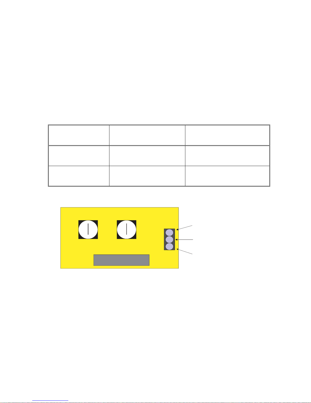
T2M Leaf Delay Card
Description:
The T2M Leaf Delay Card will control the opening and closing of the second leaf in a two-leaf gate system. With
the card installed and the potentiometers adjusted, the first gate leaf will open first followed by the second when
an OPEN command is issued. When a CLOSE command is issued, the second leaf will close first followed by the
first leaf. There are two adjustable potentiometers on the card. The Open Delay Timer sets the delay between
the opening of the first leaf and the opening of the second leaf. The Close Delay timer sets the delay between
the closing of the second leaf and the closing of the first leaf. There are also inputs on the card for Open and
Close Limit switches for the second leaf, if limit switches are required.
Adjustable Timers:
Timer Description
Minimum Delay
Maximum Delay
Open Timer (Left)
0 Seconds
15 Seconds
Close Timer (Right)
0 Seconds
15 Seconds
Board Terminals:
Installation Instructions:
To install the leaf delay card, simply plug it into the card slot marked “2 Motor Card” on the G2M Control Board.
Adjustment Procedure:
1. To set the amount of delay between the first leaf opening and the second leaf opening, turn the Open Delay
Timer (left timer) with a small screwdriver. To increase the open delay, turn the timer counter-clockwise. To
Decrease the open delay, turn the delay timer clockwise.
2. To set the amount of delay between the second leaf closing and the first leaf closing, turn the Close Delay
Timer (right timer) with a small screwdriver. To increase the close delay, turn the timer counter-clockwise.
To decrease the close delay, turn the timer clockwise.
-14-

G2M CLASSIC | Rev. 2018.1.1
FINAL SYSTEM WARNINGS
Following all of the setup instructions, you should now have a working system with
moving components. Byan Systems, Inc. issues the following warnings for your
safety:
READ ALL OWNER’S MANUALS AND SAFETY INSTRUCTIONS
MOVING GATE CAN CAUSE SERIOUS INJURY OR DEATH.
Keep Clear! Gate may move at any time without warning.
Do not allow children to operate the gate or play in the gate area.
This gate is for vehicles ONLY.
All pedestrians must use a separate entrance.
If entrapment protection is set up by constant hold control, an automatic closing
device shall not be used with this gate operator.
-15-

G2M CLASSIC | Rev. 2018.1.1
BYAN SYSTEMS, INC.
FIVE YEAR LIMITED WARRANTY
This warranty pertains only to products manufactured for or by BYAN SYSTEMS, INC. for gate operating
systems, accessories, and equipment. These products are warranted against all defective material for
sixty months from the date of sale.
Defective material returned must be prepaid and accompanied by a BYAN SYSTEMS, INC. return
authorization number within the warranty period for repair or replacement at the discretion of BYAN
SYSTEMS, INC. BYAN SYSTEMS, INC. will return warranted item freight prepaid ground service via
U.P.S.
This warranty extends only to wholesale customers who buy direct from BYAN SYSTEMS, INC. through
normal distributor channels. BYAN SYSTEMS, INC. does not warranty its products to the end
user/consumer. Consumers should inquire from their selling dealer as to the nature and extent of the
dealer’s warranty, if any. There are no obligations or liabilities on the part of BYAN SYSTEMS, INC. for
consequential damages arising out of, or in connection with, the use or performance of these products
or other indirect damages with respect to loss of property, revenue or profit, cost of removal, original
installation or reinstallation.
Warranty will be considered void if damage or malfunction was due to improper, inadequate and/or
negligent installation or the use of improper power source, or if the damage was caused by fire, flood,
lightning, electrical power surge, explosion, windstorm or hail, aircraft or vehicles, vandalism, riot or
civil commotion, or acts of God. All implied warranties for fitness are limited in duration to sixty months
from date of sale by BYAN SYSTEMS, INC. Some states do not allow for the length of the term of this
implied warranty, so this limitation may not apply to you. This warranty by BYAN SYSTEMS, INC. is in
lieu of all warranties expressed or implied.
Product delivery time is subject to availability. BYAN SYSTEMS, INC. is not responsible for any damages
caused by delays in shipping or product availability.
-16-
 Loading...