

Bxterra SP2200LCDRT2U, SP2200LCDRTXL2U, SP1000LCDRTXL2U, SP3000LCDRTXL2U, SP3000LCDRT2U User Manual
...Page 1

USER MANUAL
SP SMART SINE WAVE UPS
SP3000LCDRT2U | SP3000LCDRTXL2U
SP2200LCDRT2U | SP2200LCDRTXL2U
SP1500LCDRT2U | SP1500LCDRTXL2U
SP1000LCDRT2U | SP1000LCDRTXL2U
www.bxterra.com
Page 2

1
Page 3

TABLE OF CONTENTS
WARRANTY & REGISTRATION...........................
SAFETY INSTRUCTIONS.....................................
INSTALLATION & OPERATION..........................
PRODUCT OVERVIEW........................................
BATTERY REPLACEMENT...................................
BATTERY KIT ASSEMBLY....................................
BUTTON FUNCTIONS.........................................
LCD DISPLAY.......................................................
AUDIBLE ALARMS...............................................
LCD DISPLAY WORD INDEX...............................
UPS SETTINGS.....................................................
3
3-4
5-7
7-8
8-9
9-10
10
11
11
11
12-14
FAULT CODES.....................................................
WARNING INDICATORS.....................................
TROUBLESHOOTING..........................................
STORAGE AND MAINTENANCE.........................
TECHNICAL SPECIFICATIONS............................
BATTERY PACK SPECIFICATIONS......................
WARRANTY INFORMATION..............................
15
15
16
16
17-18
18
18
2
Page 4

PRODUCT REGISTRATION
This bXterra product is constructed to provide unmatched power protection, quality and performance for the duration of its lifetime. Please take a few minutes to
register your new product at www.bxterra.com/registration. Registration certies your product’s warranty, conrms your ownership in the event of a product loss or
theft and entitles you to free technical support. Please register your product now to receive the benets of bXterra ownership.
SAFETY
SAVE THESE INSTRUCTIONS: This manual contains important instructions that
should be followed during installation and maintenance of the UPS and its
batteries.
1. This unit is intended for installation in a controlled environment (a
temperature-controlled and indoor area free of conductive contaminants).
Please avoid installing the UPS in locations where there is standing or running
water, dust, direct sunlight or excessive humidity.
2. Use caution when lifting the UPS. Because of the considerable weight of
all rack-mount UPS systems, at least two people should assist in lifting and
installing them.
3. Connect your UPS directly to a properly grounded AC power outlet with fuse
or circuit breaker protection. Do not plug the unit into an outlet that is not
grounded. Turn o and unplug the unit if you need to de-energize it.
4. For best performance, keep the indoor temperature around the unit between
32⁰ F and 104⁰ F (0⁰ C and 40⁰ C).
5. Do not attach medical equipment or non-computer related items, such as lifesupport equipment, microwave ovens or vacuum cleaners to the UPS. bXterra
does not sell equipment meant for life-support or medical applications. Visit our
website for more information about devices appropriate to plug into this UPS.
6. Only stand or set up the UPS in the direction specied in the Installation and
Operation section of this manual. Do not block fans and leave adequate space
around all sides of the UPS for proper ventilation. Do not expose the unit to
direct sunlight and do not install the unit near heat-emitting appliances such
as a space heater or furnace. This could negatively impact the unit’s internal
cooling system and cause product damage not covered under warranty.
7. As dened in the Protection of Information Technology Equipment ANSI/
NFPA 75, this UPS is not for use in a computer room (US installations only).
Contact bXterra to order a special battery kit if needed to meet the ANSI/NFPA
75 requirement.
8. When mounting the UPS system in a tower orientation, make sure the LCD
screen panel is at the top of the UPS, not the bottom.
9. Do not plug the UPS input into its own output. Do not attach a power strip or
surge protector to the UPS.
10. Do not modify the UPS’s plug and do not use an adapter that would
eliminate the UPS’s ground connection.
11. Do not use extension cords to connect the UPS to an AC outlet.
12. The EPO and USB circuits are an IEC 60950-1 safety extra low voltage (SELV)
circuit. This circuit must be separated from any hazardous voltage circuits by
reinforced insulation.
13. If the UPS receives power from a motor-powered AC generator, the
generator must provide clean, ltered, computer-grade output. Consult your
generator’s manual to see if it meets these specications.
14. The main power outlet that supplies the UPS should be easily accessible and
near the UPS.
15. To reduce the risk of re or electric shock, do not use the unit on any
transportation such as airplanes or ships. The eect of shock or vibration
caused during transit and the damp environment can cause the unit to short
out.
16. When installing the equipment, please ensure that the sum of the leakage
current of the UPS and the connected devices does not exceed 3.5mA.
17. Do not disconnect the power cable on the UPS system or the building wiring
outlet (grounded outlet) during operation since this would cancel the protective
grounding of the UPS system and of all connected loads.
Battery Warnings:
• The UPS system operates with hazardous voltages. Repairs should only be
performed by qualied maintenance personnel.
• Do not operate the UPS without batteries.
• Caution - risk of electric shock. Even after the unit is disconnected from
the main power source, (building wiring outlet), components inside the
UPS system are still connected to the battery and electrically live and
dangerous.
• Before carrying out any kind of service and/or maintenance, disconnect
the batteries and verify that no current is present and no hazardous
voltage exists in the terminals of high-capability capacitors, such as BUScapacitors.
• To avoid electrical shock, turn o the unit and unplug it from the AC power
source before servicing the battery.
• Only persons who are adequately familiar with batteries and with the
required precautionary measures may replace batteries and supervise
operations. Unauthorized persons must be kept well away from the
batteries.
• Do not dismantle the UPS during battery replacement.
• Caution - risk of electric shock. The battery circuit is not isolated from
the input voltage. Hazardous voltages may occur between the battery
terminals and the ground. Before touching, please verify that no voltage
is present.
• When changing batteries, install the same number and same type of
batteries.
• Do not attempt to dispose of batteries by burning them. This could cause
an explosion.
• Do not open or destroy batteries. Escaping electrolytes can cause injury to
the skin and eyes. It may be toxic.
A battery can may cause a risk of electrical shock and high short-circuit
current. The following precautions should be observed when working on
batteries:
a) Remove watches, rings, or other metal objects
b) Use tools with insulated handles
c) Wear rubber gloves and boots
d) Do not lay tools or metal parts on top of batteries
e) Disconnect charging source prior to connecting or disconnecting
battery terminals
f) Determine if battery is inadvertently grounded. If inadvertently
grounded, remove source from ground. Contact with any part of a
grounded battery can result in electrical shock. The likelihood of such
shock can be reduced if such grounds are removed during installation
and maintenance.
• During hot-swap battery replacement, the UPS will not provide backup
power in the event of a blackout or other power interruptions.
External Battery Connection Warnings:
When adding external battery packs to select models with external battery
pack connectors, connect only bXterra battery packs of the correct voltage and
type. Do not connect or disconnect battery packs when the UPS is operating
on battery power. Visit www.bxterra.com to locate the supported battery
type(s) for your UPS.
3
Page 5

COMPATIBLE BATTERIES
MANUFACTURER TYPE RATING CASE FLAMMABILITY
HITACHI Battery (MH14533) GP 1272 12 V, 7.2 Ah HB
GP 1272 F2 12 V, 7.2 Ah HB
UPS 12360 6 12 V, 6.5 Ah HB
UPS 12360 7 12 V, 6.5 Ah HB
UPS 12460 12 V, 9 Ah V-0
UPS 12460 FR 12 V, 8.5 Ah HB
HR 1234W 12 V, 8.5 Ah HB
HR 1234W FR 12 V, 8.5 Ah V-0
UPS 12580 12 V, 9.4 Ah HB
UPS 12580 FR 12 V, 10 Ah V-0
TAIWAN YUASA (MH28947) NPW36-12 12 V, 7.0 Ah HB
NPW36-12FR 12 V, 7.0 Ah V-0
UXW360-12 12 V, 7.0 Ah HB
UXW360-12FR 12 V, 7.0 Ah V-0
UXW460-12 12 V, 8.0 Ah HB
UXW460-12FR 12 V, 8.0 Ah V-0
NPW45-12 12 V, 7.5 Ah HB
NPW45-12FR 12 V, 7.5 Ah V-0
SHIMASTU (MH28269) NP7-12 12 V, 7.0 Ah V-0
NP9.0-12 12 V, 9.0 Ah HB
FUJIAN MINHUA (MH47104) MS7-12 12 V, 7.0 Ah V-0
MS9-12 12 V, 9.0 Ah HB
SHENZHEN CENTER POWER (MH25860) CP1270 12 V, 7.0 Ah HB
CP1290 12 V, 9.0 Ah HB
SHENZHEN LEOCH BATTERIES (MH26866) DJW12-7.0 12 V, 7.0 Ah HB
DJW12-7.0 FR 12 V, 7.0 Ah V-0
DJW12-9.0 12 V, 9.0 Ah HB
DJW12-9.0 FR 12 V, 9.0 Ah V-0
DJW12-10 12 V, 10 Ah HB
DJW12-10 FR 12 V, 10 Ah V-0
SHENZHEN RITAR POWER (MH28539) RT1270 12 V, 7.0 Ah HB
RT1290 12 V, 9.0 Ah HB
4
Page 6
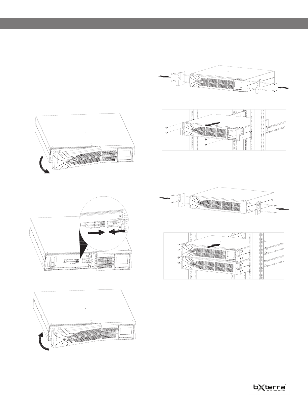
INSTALLATION AND OPERATION
NOTE: Before installation, please inspect the unit. Be sure that nothing inside
the package is damaged. Please keep the original package in a safe place for
future use.
What’s included in the box:
1. UPS System
2. User Manual
3. USB A+B Type Cable
4. Ear Racks x 2
The UPS is shipped without the battery connected. Before installing the UPS,
please follow the steps below to reconnect the battery wires.
STEP 1: Remove the front panel.
5. Screws x 8
6. Tower Stands x 4
7. Phone Line Cable x 1
8. Serial Port Cable x 1
Rack-mount Installation
CAUTION – Do NOT use the mounting brackets to lift the unit. The mounting
brackets are only for securing the unit to the rack.
Install UPS alone
STEP 2: Connect the AC input and reconnect the battery wires.
STEP 3: Put the front panel back on the unit.
Install UPS and external battery
5
Page 7
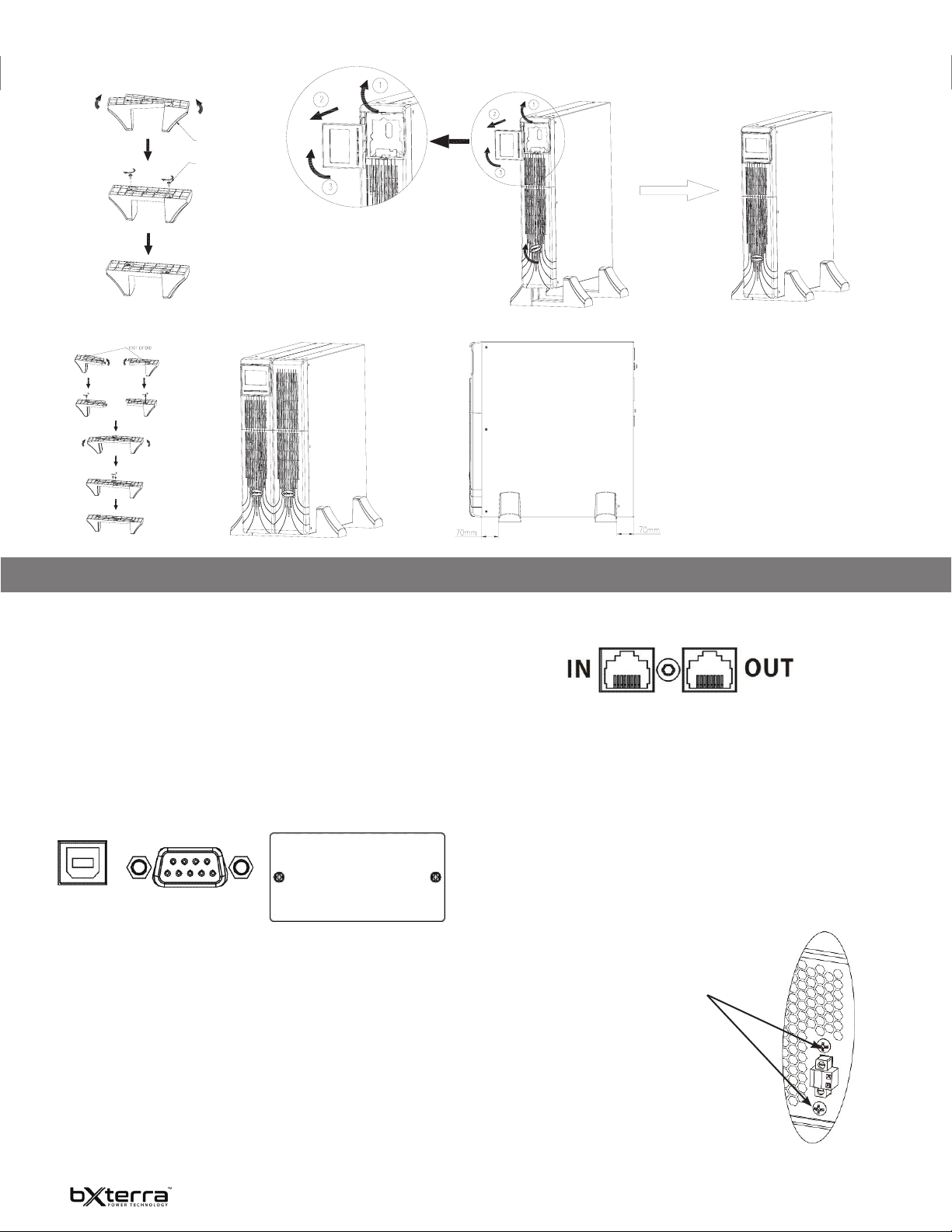
Tower Installation
STEP 1 STEP 2 STEP 3
TOWER STAND
SCREW M4 X 8
Install UPS and external battery in tower mode
NOTE: When setting up
the UPS and/or EBM with
tower stands, please
ensure the tower stands
are installed a distance of
70mm away from the edge
of the unit.
INSTALLATION AND OPERATION CONTINUED
Set Up The UPS
Step 1: UPS input connection
Plug the UPS into a 2-pole, 3-wire, grounded receptacle (wall outlet) only.
Step 2: UPS output connection
There two types of outputs: Critical outlets and Noncritical outlets. Please connect noncritical loads to the Noncritical outlets and critical loads to the Critical
outlets.
Step 3: Communication connection
Communication ports:
To allow for unattended UPS shutdown/start-up and status monitoring, connect
one end of the communication cable to the USB/RS-232 port and the other end
to the communication port of your PC. With the monitoring software installed,
USB RS-232 PORT NETWORK SLOT
you can schedule UPS shutdown/start-up and monitor UPS status through the
PC.
The UPS is equipped with a network slot for either the SNMP or AS400 card.
After installing either the SNMP or AS400 card in the UPS, it will provide
advanced communication and monitoring options.
Note: The USB port and RS-232 port can’t work at the same time.
Step 4: Network connection
NETWORK/FAX/PHONE SURGE PORT
Connect a single modem/phone/fax line into the surge-protected “IN” outlet on
the back panel of the UPS unit. Connect from “OUT” outlet to the equipment
with another modem/fax/phone line cable.
Step 5: Disable and enable EPO function
This UPS is equipped with EPO (Emergency Power o) function. By default, the
UPS is delivered from the factory with Pin 1 and Pin 2 closed (a metal plate
is connected to Pin 1 and Pin 2) for UPS normal operation. To activate EPO
function, remove two screws on the EPO port and the green connector will be
removed. As a default, the EPO function is closed during normal UPS operation.
Note: The EPO function logic can be set up via an LCD setting. Please refer to
Program 7 in the UPS setting for details.
To activate the EPO function, remove
these two screws.
As a default, the EPO function is closed
during normal UPS operation.
6
Page 8
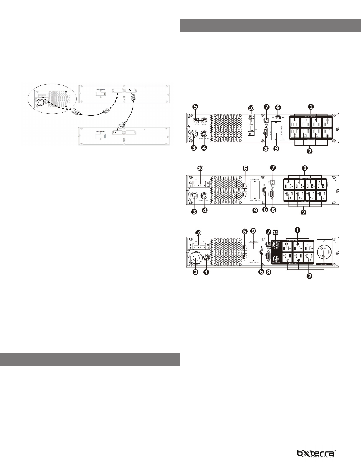
Step 6: Externed battery module connection
Connect one end of the external battery cable to the UPS unit and the other end
to the battery module. See the chart below for detailed instructions.
CAUTION: Connection to an external battery should be installed by service
personnel only.
NOTE: If connecting more than one Extended Battery Module, make sure to connect
the load at 80% of the UPS’s capacity.
EBM
PRODUCT OVERVIEW
Introduction
Thank for choosing a bXterra Uninterruptible Power Supply. This UPS system is
ENERGY STAR
less power, reduce heat and improve UPS operation.
The SP Smart Sine Wave UPS series provides protection from utility power that
may not always be safe for your devices. Each unit provides 1,372 Joules of
surge suppression and supplies battery backup during power disruptions using
maintenance-free batteries. Each SP Series model ensures consistent power
to your connected equipment and critical devices. Each model also comes with
access to PowerFrame™ Business Edition management software to remotely set
up and manage your bXterra UPS.
SP1000LCDRT2U | SP1000LCDRTXL2U | SP1500LCDRT2U | SP1500LCDRTXL2U
®
-certied and uses our GreenTech™ Bypass Design to consume
UPS
To connect an Extended Battery Module:
1. Turn o the UPS utility input.
2. Open the front-left cover on the UPS and the Extended Battery Module
(EBM) and disconnect the internal batteries.
3. Remove the EBM-terminal covers from the UPS and the EBM and connect
one end of the external-battery cable to the UPS and one end to the
battery cabinet as shown in the gure above.
• If connecting more than one external battery, connect one end of the
external battery cable to the second connector on the battery module,
then connect the other end to the next battery module as shown in
the gure above.
4. Once the UPS and EBM(s) are connected, secure the connection with the
screws, reconnect the internal batteries, and replace the front-left covers
on the units.
NOTE: After install and initial start-up, set the number of installed battery modules
in the UPS Settings.
NOTE: When 2 or more external battery modules are used with bXterra
SP1000/2200/3000 series models, the UPS load rating is decreased by 20%.
Step 7: Turn on the UPS
Press the ON/Mute button on the front panel for two seconds to power on the
UPS.
Note: The battery charges fully during the rst ve hours of normal operation.
Do not expect full battery capability during this initial charge period.
Step 8: Install software
For optimal computer system protection, install UPS monitoring software to
fully congure UPS shutdown and operation. Please follow steps below to
download and install the monitoring software:
1. Go to the website http://www.bxterra.com/downloads
2. Click PowerFrame™ software icon and then choose your required OS to
download the software
3. Follow the on-screen instructions to install the software
4. When your computer restarts, the monitoring software will appear as a Green
“X” icon located in the system tray
EBM
AUTOMATIC VOLTAGE REGULATOR
The SP Smart Sine Wave UPS series adjusts inconsistent utility power to normal
levels that are safe for your equipment. The AVR feature of this UPS can take
erratic incoming utility power and correct it to safe levels. AVR automatically
increases utility power that is too low or decreases utility power that is too high
to a consistent 110 or 120 volts.
SP2200LCDRT2U | SP2200LCDRTXL2U
SP3000LCDRT2U | SP3000LCDRTXL2U
1. Noncritical outlets
Connect noncritical loads to these outlets. These outlets are programmable.
2. Critical outlets
Connect critical loads to these outlets. These outlets are not programmable.
3. AC input
Plug in the main power cord for the UPS here.
4. Input circuit breaker
This breaker provides overload and fault protection. If it trips, remove some
of the load then reset it by pressing it in.
5. Network/Fax/Modem surge protection
These ports protect equipment from surges over a single phone line or
network connection.
6. Emergency Power O function connector (EPO)
This connector allows for the installation of an EPO function, a feature
which allows for a rapid turn-o of the UPS in case of an emergency.
7. USB communication port
This port connects the UPS to any computer to download the UPS-mon-
itoring software, PowerFrame™. Instructions for this can be found in the
Installation section of this manual.
8. RS-232 communication port
This port allows for the connection of devices via the RS-232 protocol.
9. SNMP network slot
This port allows for installation of either the SNMP or AS400 card. These
cards will provide advanced communication and monitoring options for the
UPS.
10. External battery connector (only available for the XL model)
Allows for the connection of bXterra External Battery Modules to provide
additional power and battery backup.
11. Output Circuit Breaker (only available on the SP3000 & SP3000XL models)
These resettable circuit breakers provide output outlets with protection
from overload.
7
Page 9
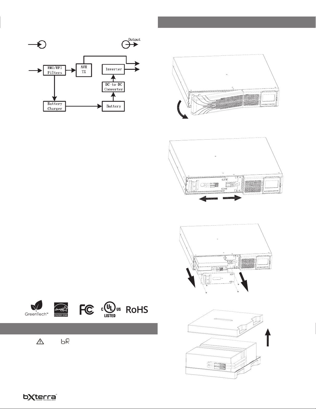
OPERATING PRINCIPLE
The operating principle of the UPS is shown below.
The UPS is composed of Power Input, EMI/RFI Filters, Inverter, Battery Charger,
DC-to-DC Converter, Battery, AVR TX and UPS Output.
CERTIFICATIONS
NOTE: This equipment has been tested and found to comply with the limits
for a Class B digital device, pursuant to Part 15 of the FCC Rules. These limits
are designed to provide reasonable protection against harmful interference
in a residential installation. This equipment generates uses and can radiate
radio frequency energy and, if not installed and used in accordance with
the instructions, may cause harmful interference to radio communications.
However, there is no guarantee that interference will not occur in a particular
installation. If this equipment does cause harmful interference to radio or
television reception, which can be determined by turning the equipment o and
on, the user is encouraged to try to correct the interference by one or more of
the following measures:
- Reorient or relocate the receiving antenna
- Increase the separation between the equipment and receiver
- Connect the equipment into an outlet on a circuit dierent from that to
which the receiver is connected
- Consult an experienced radio/TV technician for help
WARNING: Changes or modications not expressly approved by the party
responsible for compliance could void the user’s authority to operate the
equipment.
Our GreenTech™ UPS Bypass Design strives to deliver better operating performance while using less power required by other uninterruptible power supplies.
The technology inside a bXterra UPS allows current to bypass the transformer
and automatic voltage regulation (AVR) when utility power is running normally,
reducing energy consumption. This can lead to substantial energy savings when
utility power is running normally on a consistent basis.
At bXterra, we want you to know that you’re not only protecting your devices
and equipment when purchasing our products, but you’re protecting the environment as well. Aside from being ENERGY STAR®-compliant, we are committed
to and supporters of the Restriction of Hazardous Substances (RoHS) directive,
which strictly limits the use of six hazardous substances (lead, mercury, cadmi-
um, hexavalent chromium, polybrominated biphenyls (PBBs) and polybrominat-
ed diphenyl ether (PBDE)) in electrical equipment.
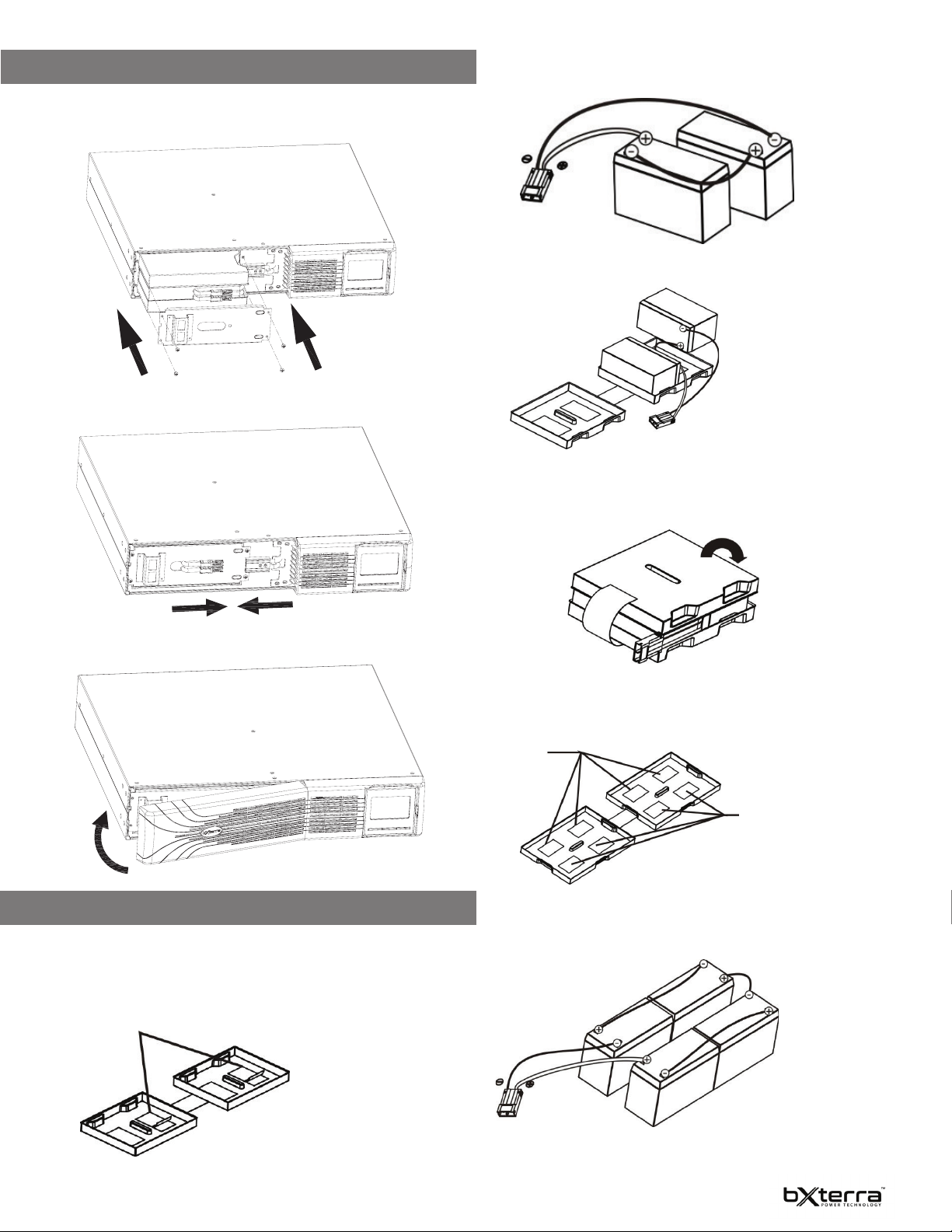
BATTERY REPLACEMENT
NOTE: A small amount of arcing may occur when connecting the internal batteries.
This is normal and will not harm personnel. Connect the cables quickly and rmly.
STEP 1: Remove the front panel.
STEP 2: Disconnect battery wires.
STEP 3: Pull out the battery box by removing two screws on the front
panel.
STEP 4: Remove the top cover of the battery box and replace the
internal batteries.
BATTERY REPLACEMENT ADVISORY
When the icon and are ashing on the LCD display and the alarm is
sounding every two seconds, the batteries may need replacing. Contact your
service representative to order new batteries.
NOTE: DO NOT DISCONNECT the batteries while the UPS is in Battery mode.
Batteries can be replaced easily without turning the UPS o or disconnecting
the load. If you prefer to remove input power to change the batteries, press the
OFF button on the front panel for two seconds to power o the UPS and switch
the utility power o where the UPS is connected.
8
Page 10
BATTERY REPLACEMENT CONTINUED
STEP 5: After replacing the batteries, put the battery box back to its
original location and screw it in tightly.
STEP 6: Reconnect the battery wires.
STEP 2: Connect all battery terminals by following the picture below.
STEP 3: Put assembled battery packs on one side of the plastic shells as shown
below.
STEP 4: Cover the other side of the plastic shell as shown in the picture below.
The battery kit assembly is now completed.
STEP 7: Put the front panel back on the unit.
BATTERY KIT ASSEMBLY (OPTIONAL)
NOTE: Please assemble the battery kit rst before installing it inside of the UPS.
Please select the correct battery kit procedure below to assemble it.
2 BATTERY KIT
STEP 1: Remove the adhesive tape.
TAPE
4 BATTERY KIT
STEP 1: Remove the adhesive tape.
TAPE
TAPE
STEP 2: Connect all battery terminals by following the picture below.
9
Page 11
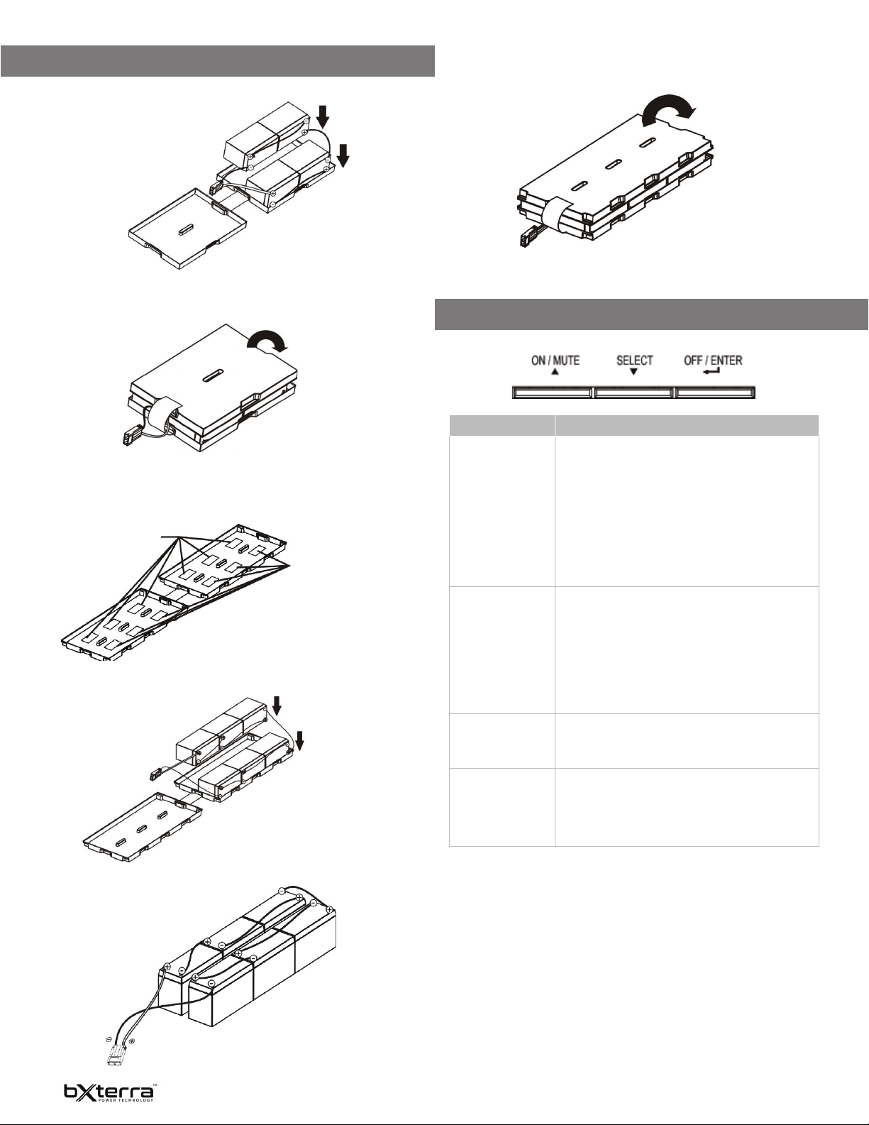
BATTERY KIT ASSEMBLY CONTINUED
STEP 3: Put assembled battery packs on one side of the plastic shells as shown
below.
STEP 4: Cover the other side of the plastic shell as shown in the picture below.
The battery kit assembly is now completed.
6 BATTERY KIT
STEP 1: Remove the adhesive tape.
TAPE
TAPE
STEP 2: Put assembled battery packs on one side of the plastic shells as shown
below.
STEP 4: Cover the other side of the plastic shell as shown in the picture below.
The battery kit assembly is now completed.
BUTTON FUNCTIONS
BUTTON FUNCTION
ON/MUTE • Turn on the UPS: Press and hold ON/Mute button
for at least two seconds to turn on the UPS.
• Mute the alarm: After the UPS is turned on in
Battery Mode, press and hold this button for at
least three seconds to disable or enable the alarm
system. Note: This will not work when warnings or
errors occur.
• Up key: Press this button to display the previous
selection in UPS Setting Mode.
• Switch to UPS Self-Test Mode: Press and hold ON/
Mute button for three seconds to enter UPS selftesting while in AC Mode.
SELECT • Switch LCD message: Press this button to
change the LCD message for input voltage, input
frequency, battery voltage, output voltage and
output frequency.
• Setting Mode: Press and hold this button for three
seconds to enter UPS Setting Mode when the UPS
is o .
• Down key: Press this button to display the next
selection in UPS Setting Mode.
STEP 3: Connect all battery terminals by following the picture below.
OFF/ENTER • Turn o the UPS: Press and hold this button at
least three seconds to turn o the UPS.
• Con rm selection key: Press this button to
con rm the selection in UPS Setting Mode.
ON/Mute + Select • Exit Setting Mode or return to the upper menu:
When working in Setting Mode, press the ON/
Mute and Select buttons simultaneously to return
to the main menu. If you are already at the main
menu, press these two buttons at the same time
to exit the Setting Mode.
10
Page 12
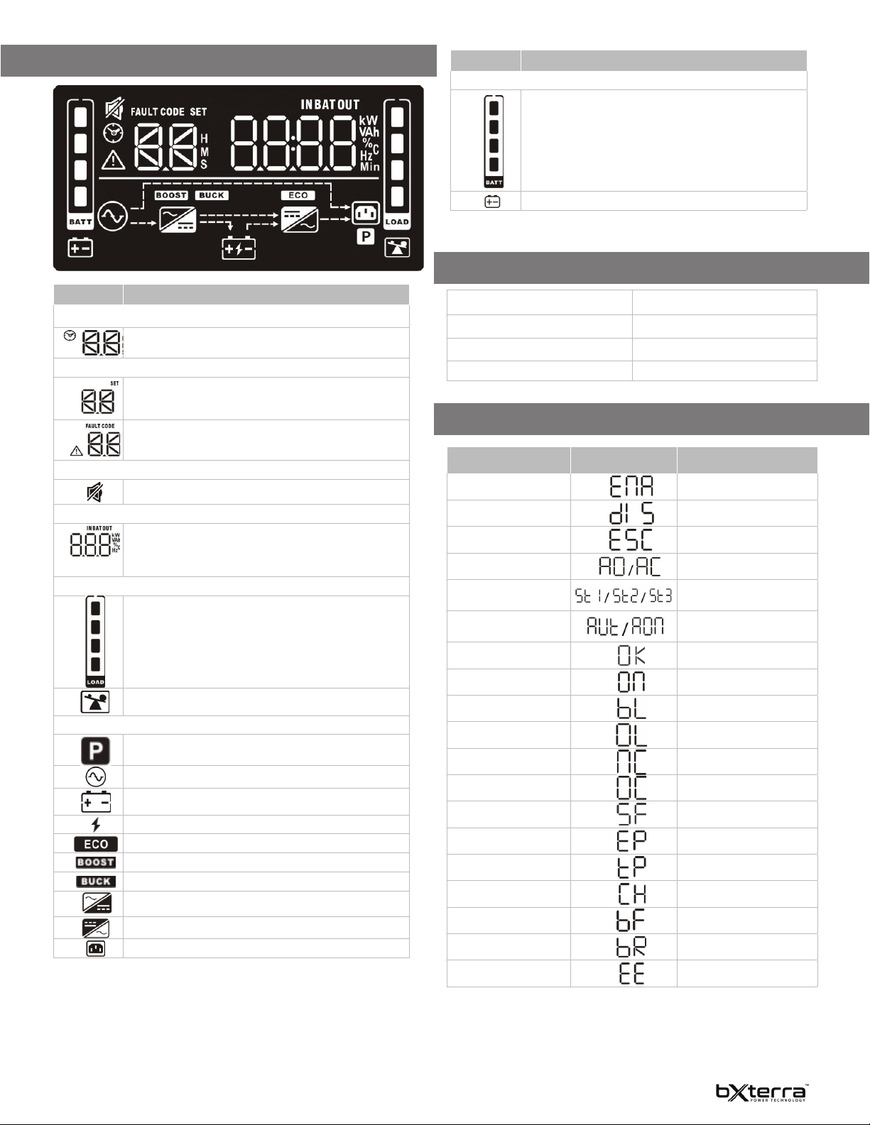
LCD DISPLAY
DISPLAY FUNCTION
Battery information
Indicates the battery level by 0-24%, 25-49%, 50-74%, and
75-100%.
Indicates low battery.
AUDIBLE ALARMS
DISPLAY FUNCTION
Backup time information
Indicates the estimated backup time.
H: hours, M: minute, S: second.
Conguration and fault information
Indicates the conguration items. The conguration items
are listed in detail in the UPS Settings section of the
manual.
Indicates the warning and fault codes. The codes are listed
in detail in the Fault Codes section of the manual.
Mute operation
Indicates that the UPS alarm is disabled.
Input, Battery, Output & Load information
Indicates the input voltage, input frequency, battery
voltage, battery capacity, output voltage, output frequency,
load current and load percentage.
k: kilo, W: watt, V: voltage, A: ampere, %: percent, Hz: frequency
Load information
Indicates the load level by 0-24%, 25-49%, 50-74% and
75-100%.
Indicates overload.
Programmable/Noncritical outlets information
Indicates that programmable management outlets are
working.
Indicates the UPS is connected to main power.
Indicates the battery is working.
Indicates charging status.
Indicates the ECO Mode is enabled.
Indicates the UPS is working in Boost Mode.
Indicates the UPS is working in Buck Mode.
Indicates the AC to DC circuit is working.
Indicates the inverter circuit is working.
Indicates the output is working.
Battery Mode Beeping every 10 seconds
Low Battery Beeping every two seconds
Overload Beeping every second
Fault Continuously beeping
LCD DISPLAY WORD INDEX
Abbreviation Display Content Meaning
ENA
DIS
ESC
AO/AC
ST/1/2/3
AUT/AON Automatic/Always On
OK
ON
BL
OL
NC
OC
SF
EP
TP
CH
BF
BR
EE
Input Waveform Sensitivity
Enable
Disable
Escape
Active Open/Active Close
1/2/3
OK
ON
Battery Low
Overload
Battery Not Connected
Overcharge
Site Fault
EPO
Temperature
Charger
Battery Fault
Battery Replacement
EEPROM error
11
Page 13
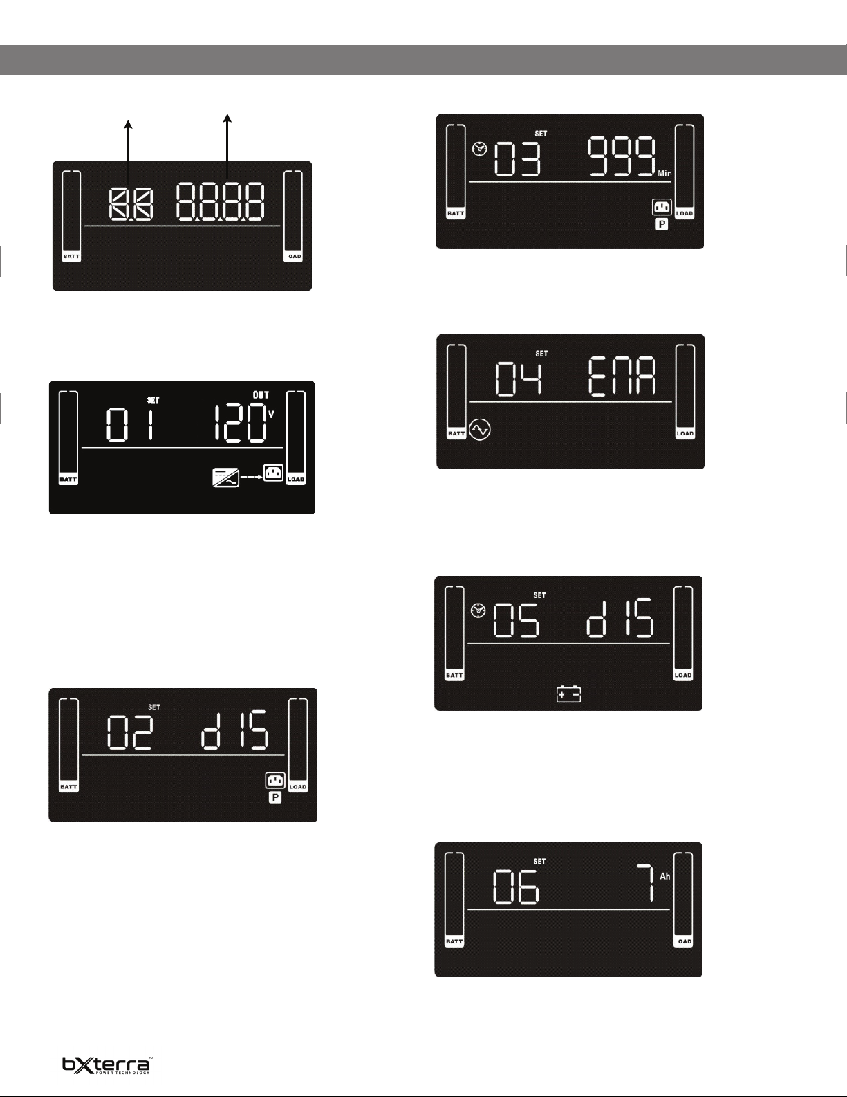
UPS SETTINGS
Parameter 1
Parameter 2
There are two parameters to set up the UPS.
Parameter 1 is used for program alternatives.
Refer to the following LCD illustrations.
Parameter 2 is for setting options or values for each program.
01: OUTPUT VOLTAGE SETTING
03: PROGRAMMABLE OUTLETS SETTING
SETTING
Parameter 2: Set up backup time limits for programmable outlets.
0-999: setting the backup time limits in minutes from 0-999 for programmable
outlets which connect to noncritical devices on Battery Mode. (Default: 999)
04: SITE FAULT DETECTION ENABLE/DISABLE
SETTING
Parameter 2: Output voltage
For 120VAC models, you may choose the following output voltage:
100: presents output voltage is 100VAC
110: presents output voltage is 110VAC
115: presents output voltage is 115VAC
120: presents output voltage is 120VAC (Default)
125: presents output voltage is 125VAC
02: PROGRAMMABLE/NONCRITICAL OUTLETS ENABLE/DISABLE
SETTING
Parameter 2: Enable or disable programmable outlets.
ENA: Programmable outlets enabled
DIS: Programmable outlets disabled (Default)
SETTING
Parameter 2: Enable or disable site fault detection. You may choose the
following two options:
ENA: Site fault detection enable (Default)
DIS: Site fault detection disable
05: AUTONOMY LIMITATION SETTING
SETTING
Parameter 2: Set up backup time on Battery Mode for all outlets.
0-999: setting the backup time in minutes from 0-999 for all outlets on Battery
Mode.
DIS: By default, the autonomy limitation is disabled. Battery backup time will
depend on battery capacity.
Note: When the setting is “0”, the backup time will be only 10 seconds.
06: BATTERY TOTAL AH SETTING
SETTING
Parameter 2: Set up the battery total AH of the UPS.
7-999: Setting the battery total capacity from 7-999 in AH. Please set the correct
battery total capacity if Extended Battery Module is connected.
12
Page 14
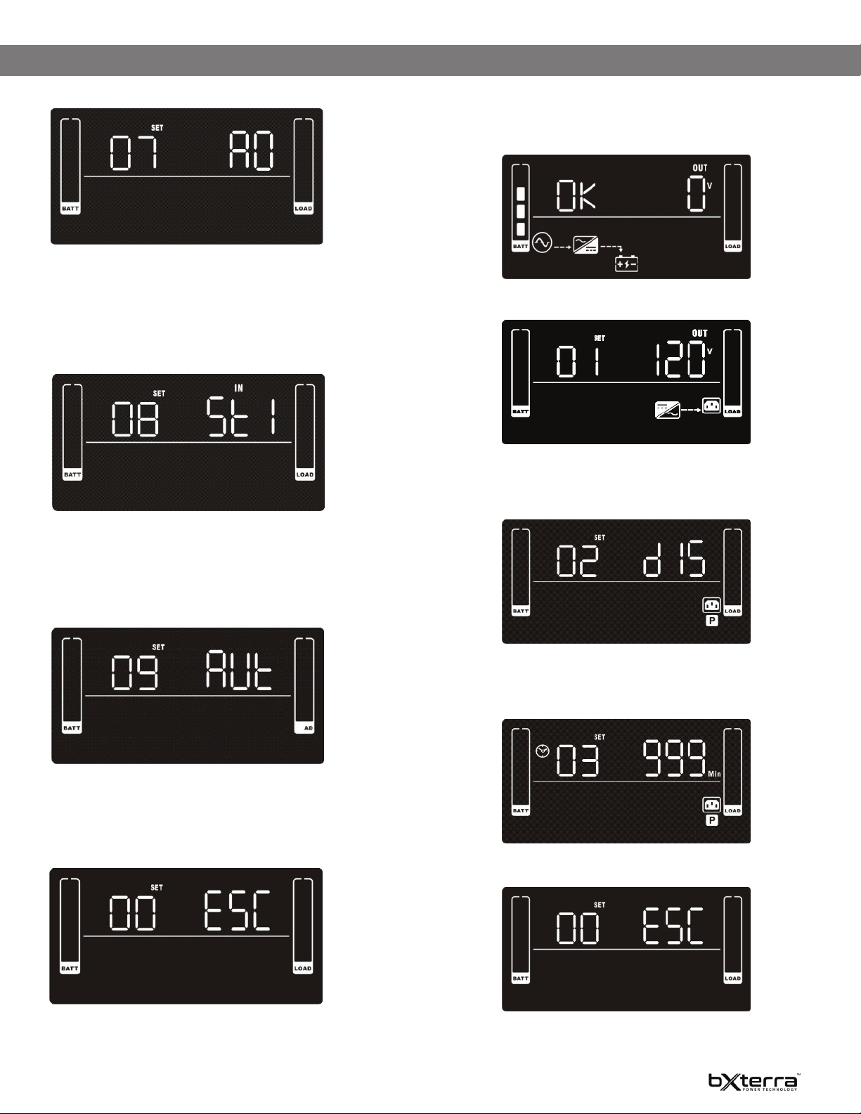
UPS SETTINGS CONTINUED
07: EPO LOGIC SETTING
SETTING
Parameter 2: Set up the EPO function control logic.
AO: Active Open (Default). When AO is selected as EPO logic, it will activate EPO
function with Pin 1 and Pin 2 in open status.
AC: Active Close. When AC is selected as EPO logic, it will activate EPO function
with Pin 1 and Pin 2 in closed status.
08: INPUT WAVEFORM SENSITIVITY SETTING
SETTING
Parameter 2: Set Input Waveform Sensitivity.
St1: Input voltage waveform detection sensitivity is high. (Default)
St2: Input voltage waveform detection sensitivity is average.
St3: Input voltage waveform detection sensitivity is low. (Use with generators or
step wave input)
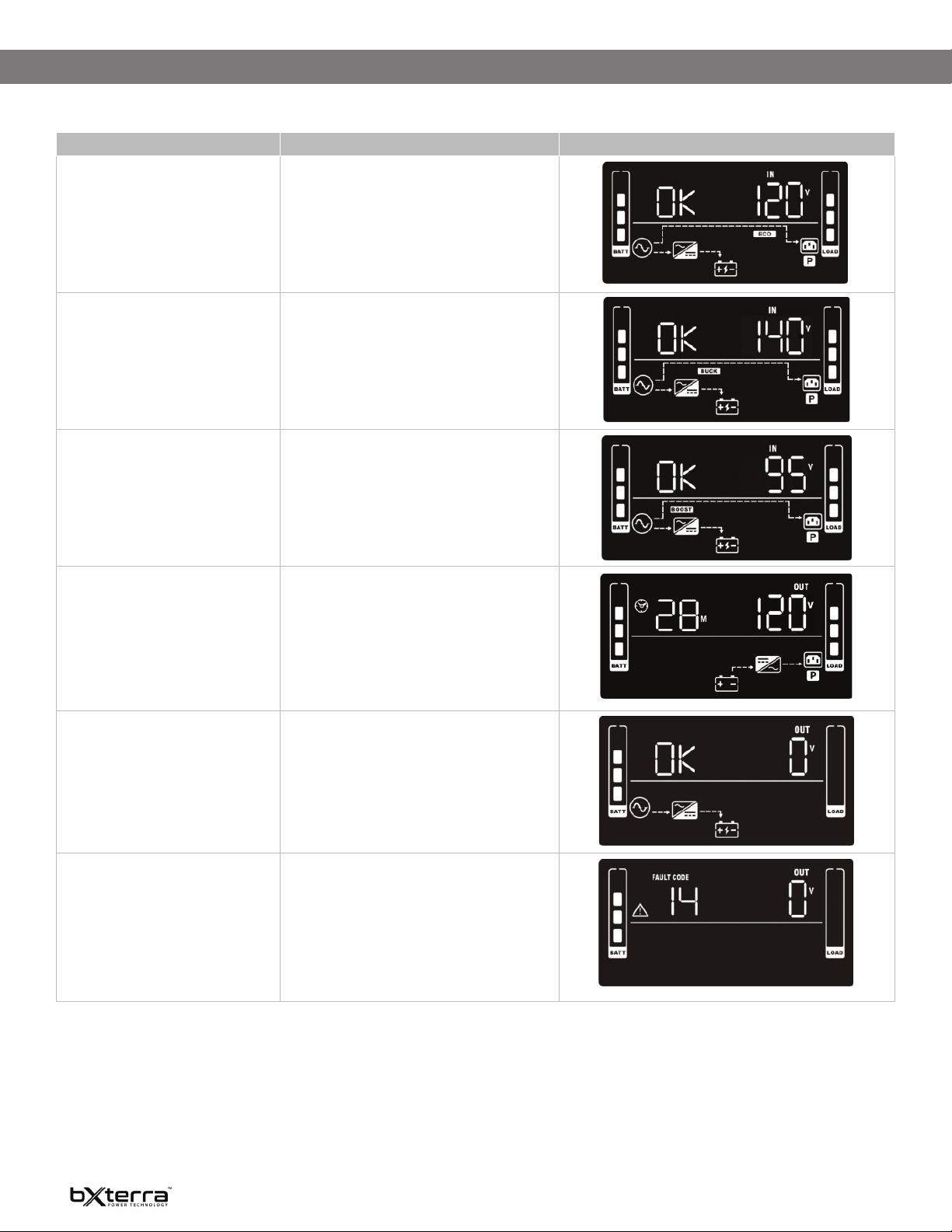
STEPS FOR SETTING PROGRAMMABLE/NONCRITICAL OUTLETS
Step 1:
Before entering Setting Mode, the UPS should be in Standby Mode (o-
charging) and make sure the battery is connected. The LCD display is shown
below.
Step 2:
Press and hold the “Selection” button for three seconds to enter Setting Mode.
Step 3:
Press the “Up” button (ON/MUTE) to switch to “02” of program list. Then press
“Enter” button to enter value setting of Parameter 2. Press the “Up” button to
change the value to “ENA” to enable the programmable outlet function. Then
press “Enter” button again to conrm the setting.
09: LCD DISPLAY BACKLIGHT SETTING
SETTING
Parameter 2: Set up the working conditions for the LCD display backlight.
Aon: LCD display backlight is on all the time.
Aut: LCD display backlight will turn o after 60 seconds of receiving no input.
(Default)
00: EXIT SETTING
SETTING
Exit the Setting Mode.
Step 4:
Press the “Up” button (ON/MUTE) again to switch to “03” of program list. Then
press “Enter” button for setting programmable outlet time. Push “Up” button to
change the value of backup time according to your demand. Then press “Enter”
to conrm the setting.
Step 5:
Press “Up” button (ON/MUTE) to switch to “00” of program list. Then press
“Enter” button to exit the setting menu.
Step 6:
Disconnect AC input and wait until the LCD display is o. The new setting will be
activated when turning on the UPS again.
13
Page 15
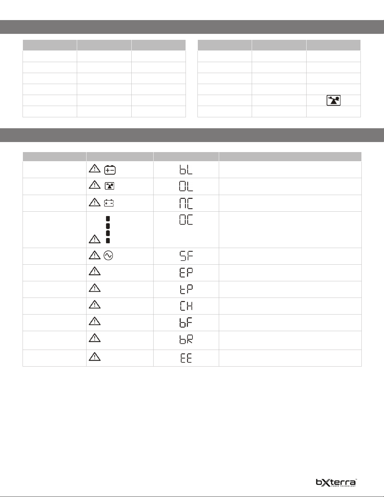
UPS SETTINGS CONTINUED
OPERATING MODE DESCRIPTION
OPERATING MODE DESCRIPTION LCD DISPLAY
ECO mode When the input voltage is within voltage regulated
range, the UPS will power the output directly from
the main power source. ECO is an abbreviation of
Eciency Corrective Optimizer. In this mode, when
the battery is fully charged, the fan will stop working
to save energy.
Buck Mode when AC power is normal When the input voltage is higher than the voltage
Boost Mode when AC power is normal When the input voltage is lower than the voltage
Battery Mode The UPS will supply backup power from the battery
Standby Mode The UPS is powered o and is not supplying output
regulation range but lower than the high-loss point,
the buck AVR will be activated.
regulation range but higher than the low-loss point,
the boost AVR will be activated.
and display estimated remaining runtime, in minutes, when the input voltage is beyond the acceptable range or a power failure occurs.
power, but is still charging its batteries.
Fault Mode When a fault occurs, the ERROR icon and the fault
code will be displayed.
14
Page 16
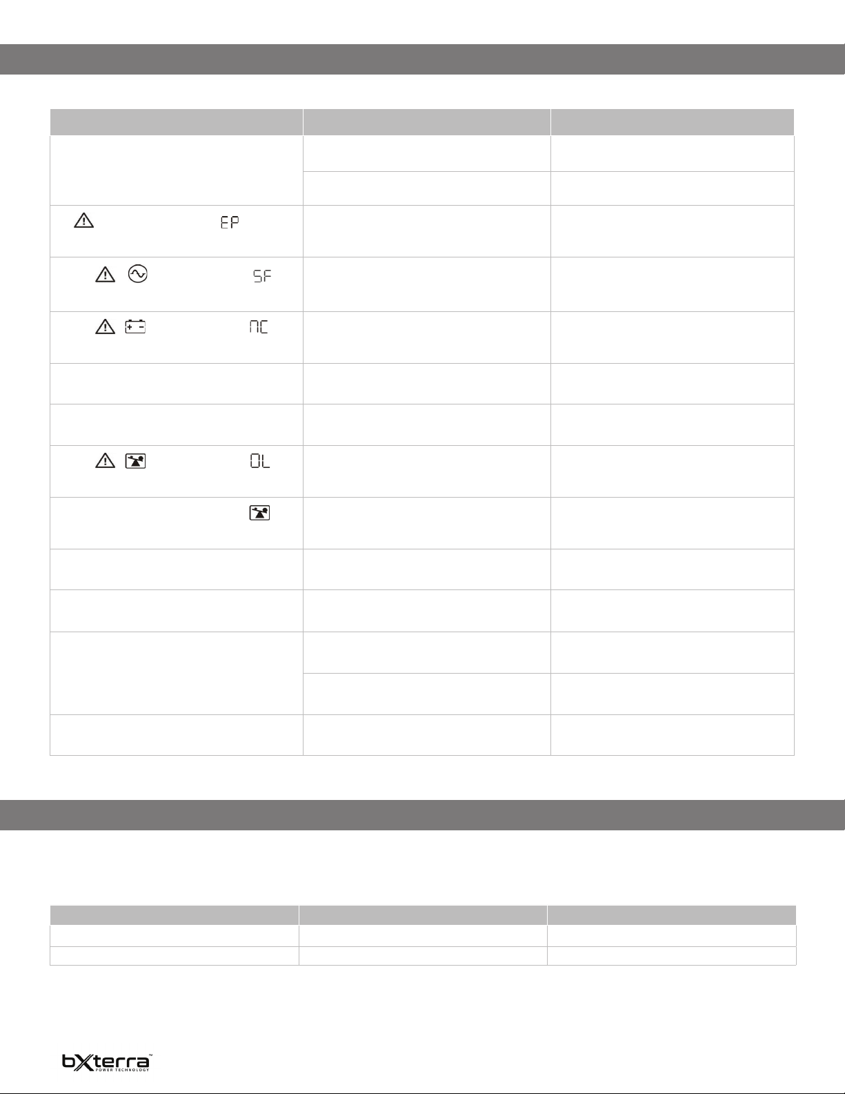
FAULT CODES
FAULT EVENT FAULT CODE ICON
Bus start fail 01 X
Bus over 02 X
Bus under 03 X
Inverter soft start fail 11 X
Inverter voltage high 12 X
Inverter voltage low 13 X
FAULT EVENT FAULT CODE ICON
Inverter output short 14 X
Battery voltage too high 27 X
Battery voltage too low 28 X
Over temperature 41 X
Overload 43
Charger failure 45 X
WARNING INDICATORS
WARNING ICON (FLASHING) CODE ALARM
Low battery Beeping every two seconds
Overload
Battery is not connected
Overcharge
Beeping every second
Beeping every two seconds
Beeping every two seconds
Site wiring fault
EPO enable
Over temperature
Charger failure
Battery fault
Battery replacement
EEPROM error Beeping every two seconds
NOTE: “Site Wiring Fault” function can be enabled/disabled via our software. Please check the software manual for details.
Beeping every two seconds
Beeping every two seconds
Beeping every two seconds
Beeping every two seconds
Beeping every two seconds
Beeping every two seconds
(At this time, the UPS is o to remind users something is wrong
with the battery)
15
Page 17
TROUBLESHOOTING
If the UPS system does not operate correctly, please refer to the table below.
SYMPTOM POSSIBLE CAUSE REMEDY
The UPS is not functioning and shows no error
indications even though the main power source is
functioning normally
icon and the warning code are ashing
The
on the LCD display and the alarm is beeping every
two seconds
The icon
ashing on the LCD display and the alarm is beeping
every two seconds
The icon
ashing on the LCD display and the alarm is beeping
every two seconds
The fault code is shown as 27 on the LCD display and
the alarm is continuously beeping
The fault code is shown as 28 on the LCD display and
alarm is continuously beeping
The icon
ashing on LCD display and the alarm is beeping
every second
The fault code is shown as 43 and the icon
is lit on the LCD display. The alarm is continuously
beeping.
The fault code is shown as 14 and the alarm is
continuously beeping
, and the warning code are
, and the warning code are
, and the warning code are
The AC input power connection is not connected
properly
The AC input is connected to the UPS output Plug the AC input power cord to the AC input
The EPO function is activated Set the circuit in the closed position to disable the
The line and neutral conductors of the UPS input are
reversed
The external or internal battery is incorrectly
connected
The battery voltage is too high or the charger is
faulty
The battery voltage is too low or the charger is faulty Contact bXterra Technical Support
The UPS is overloaded Remove excess loads from the UPS output
The UPS shut down automatically because of an
overload at the UPS output
The UPS shut down automatically because a short
circuit occurred on the UPS output
Check if the input power cord is rmly connected to
the main power source
correctly
EPO function
Rotate the main power socket by 180° and then
connect it to the UPS system
Check if the batteries are connected properly
Contact bXterra Technical Support
Remove excess loads from the UPS output and
restart it
Check output wiring and if the connected devices
are in short circuit status
The fault code is shown as 01, 02, 03, 11, 12, 13 and
41 on the LCD display and the alarm is continuously
beeping
Battery backup time is shorter than expected The batteries are not fully charged Charge the batteries for at least ve hours and then
The fault code is shown as 45 on the LCD display. At
the same time, the alarm is continuously beeping.
A UPS internal fault has occurred Contact bXterra Technical Support
check capacity. If the problem persists, contact
bXterra Technical Support.
The batteries are defective Contact bXterra Technical Support for replacement
The charger does not have output and the battery
voltage is less than 10V/PC
batteries
Contact bXterra Technical Support
STORAGE AND MAINTENANCE
The UPS system contains no user-serviceable parts. If the battery service life (3~5 years at 77°F ambient temperature) has been exceeded, the batteries must be
replaced. In this case, please contact your dealer.
Before storing, charge the UPS at least ve hours. Store the UPS covered and upright in a cool, dry location. During storage, recharge the battery in accordance with
the following table:
STORAGE TEMPERATURE RECHARGE FREQUENCY CHARGING DURATION
-13°F - 104°F Every three months 1-2 hours
104°F - 113°F Every two months 1-2 hours
16
Page 18

TECHNICAL SPECIFICATIONS
MODEL SP1000LCDRT2U SP1000LCDRTXL2U SP1500LCDRT2U SP1500LCDRTXL2U SP2200LCDRT2U SP2200LCDRTXL2U SP3000LCDRT2U SP3000LCDRTXL2U
Topology Line Interactive
INPUT
Voltage 120 VAC
Frequency Range 50/60Hz (auto-sensing)
Input Voltage Range 81-152VAC
Plug Type NEMA 5-15P, 16 AWG NEMA 5-15P, 14 AWG NEMA 5-20P, 12 AWG NEMA L5-30P, 10 AWG
Plug Style Straight Type
Cord Length 10ft
OUTPUT
VA 1000VA 1500VA 1920VA 3000VA
Watts 990W 1350W 1920W 2700W
Automatic Voltage
Regulation
On Battery Voltage 120 VAC ± 1.5%
On Battery Frequency 50/60 Hz ± 0.1 Hz
On Battery Wave Form Pure Sine Wave
Outlet Type NEMA 5-15R NEMA 5-15R NEMA 5-20R NEMA 5-20/30R
Outlet Total 8 8 8 7
Battery and Surge
Protected
Outlets - Critical Load 4 4 4 4
Load Management
Receptacles
Overload Protection Firmware / Circuit Breaker
Transfer Time 4ms Typical
BATTERY
Runtime at Half Load 10.2 minutes 12.5 minutes 12 minutes 12 minutes
Runtime at Full Load 2.9 minutes 4.4 minutes 4 minutes 3.7 minutes
Battery Type Leakproof Sealed Lead-Acid
Battery Size 12V/9AH 12V/7AH 12V/7AH 12V/9AH
Battery Quantity 2 4 6 6
User Replaceable Yes
DC System Voltage
(VDC)
Typical Recharge Time 4 hours
Extended Runtimes
Available
SURGE PROTECTION & FILTERING
Surge Suppression 1372 Joules on UL report (Maximum)
Phone Protection RJ11/
Ethernet RJ45
EMI/RFI Filtration Full time multi-pole noise ltering : 5% IEEE surge let-through : zero clamping response time : meets UL 1449
MANAGEMENT & COMMUNICATIONS
Multifunction LCD
Panel
HID Compliant USB
Port
Serial Port Yes
EPO Port Yes
Management Cable USB Cable, Serial Cable, EPO Cable(optional)
Audible Alarms Battery Mode, Low Battery, Overload, Fault
Software PowerFrame
SNMP / HTTP Remote
Monitoring
N/A Yes N/A Yes N/A Yes N/A Yes
Displays: Load/Level, Runtime, Battery Level, Battery In Use, Input Voltage, Output Voltage, Output Frequency, Overload, Wiring Fault, Battery
8 8 8 7
4 4 4 3
24VDC 48VDC 72VDC 72VDC
Power management from SNMP Manager and web browser (optional)
Boost +15% / Buck -13%
1-In, 1-Out
Voltage, Silent Mode, Normal Mode
Yes
TM
UPS Management Software
17
Page 19

TECHNICAL SPECIFICATIONS CONTINUED
MODEL SP1000LCDRT2U SP1000LCDRTXL2U SP1500LCDRT2U SP1500LCDRTXL2U SP2200LCDRT2U SP2200LCDRTXL2U SP3000LCDRT2U SP3000LCDRTXL2U
PHYSICAL
Form Factor Rack/Tower
Rack Size 2U
Dimensions (in) 17.24 × 3.46 × 16.14 17.24 × 3.46 × 20.08 17.24 × 3.46 × 24.80 17.24 × 3.46 × 24.80
Weight (lbs) 29.5 41.4 61.1 64.6
ENVIRONMENTAL
Operating Temperature 32°F to 104°F / 0°C to 40°C
Storage Temperature -13°F to 113°F / -25°C to 50°C
Operating Humidity 0% - 95%RH@32-104°F (0-40°C) non-condensing
Storage Relative
Humidity
Maximum Operating
Elevation
Maximum Storage
Elevation
Audible Noise <45dB
AC Mode Thermal
Dissipation
CERTIFICATIONS
Safety cULus, FCC Part 15 Class B, ENERGY STAR
Environmental RoHS Compliant
WARRANTY
Product Warranty 3 Year Limited
Connected Equipment
Guarantee
141 BTU/Hr 192 BTU/Hr 224 BTU/Hr 315 BTU/Hr
0 to 95%
10,000 ft / 3,000 m
50,000 ft / 15,000 m
Yes
®
Qualied
Product specications are subject to change without prior notice
EXTENDED BATTERY MODULE SPECIFICATIONS
MODEL BP24V-SP2U BP48V-SP2U BP72V-SP2U
Used with UPS Models SP1000LCDRTXL2U SP1500LCDRTXL2U SP2200LCDRTXL2U/SP3000LCDRTXL2U
Battery Type 12V/9Ah 12V/9Ah 12V/9Ah
DC System Voltage(VDC) 24VDC 48VDC 72VDC
Rack Size 2U 2U 2U
Battery Numbers 4 8 12
Dimensions (in) 17.24 x 3.46 x 16.14 17.24 x 3.46 x 20.08 17.24 x 3.46 x 24.8
Weight (lbs) 37.7 63.93 90.83
NOTE: To avoid potential problems with the UPS and/or EBM, please use the appropriate Extended Battery Module when connecting to the UPS.
WARRANTY INFORMATION
Your bXterra product comes with a Limited 3-Year Warranty. bXterra warrants this product, if used appropriately and in full accordance with all
applicable instructions, to be free from original defects in material and workmanship for 3 years from the date of initial purchase. If the product
can be proven defective in material or workmanship during that 3-year period, bXterra will, subject to the full terms and limitations of the
product’s Limited Warranty available on our website, repair or replace that product. bXterra will act on its own discretion as the sole remedy for
bXterra’s breach of its Limited Warranty. Full details of this Limited Warranty and bXterra’s Connected Equipment Guarantee can be found on
our website at www.bxterra.com/warranty or at the individual product’s page on our website. Please register your product at www.bxterra.com/
registration to certify your product’s warranty.
18
Page 20

This manual is believed to be accurate, but bXterra reserves the right to change or correct the contents of this manual at a later date and does not assume any
All content is owned by Bxterra Power Technology. All Rights Reserved.
Reproduction is prohibited without permission. www.bxterra.com.
responsibility for omissions or errors.
19
 Loading...