

Page 1
B&W Trailer Hitches
1216 Hawaii Road / PO Box 186
Humboldt, KS 66748
800.248.6564
www.turnoverball.com
620.473.3664
Fax:620.473.3766
NOTE: We recommend reading instructions before beginning the installation.
WARNING: The tow vehicle’s towing capacities should under NO circumstances be exceeded.
TurnoverballTM Gooseneck Hitch Installation Instructions
Model 1197R
Ford (1997-2003) and 2004 Ford Heritage (Old body Style)
1/2 Ton & Light 3/4 Ton, Short and Long Bed
Light Duty Body Style
Except 1997 Ford w/ Air Bag Overloads
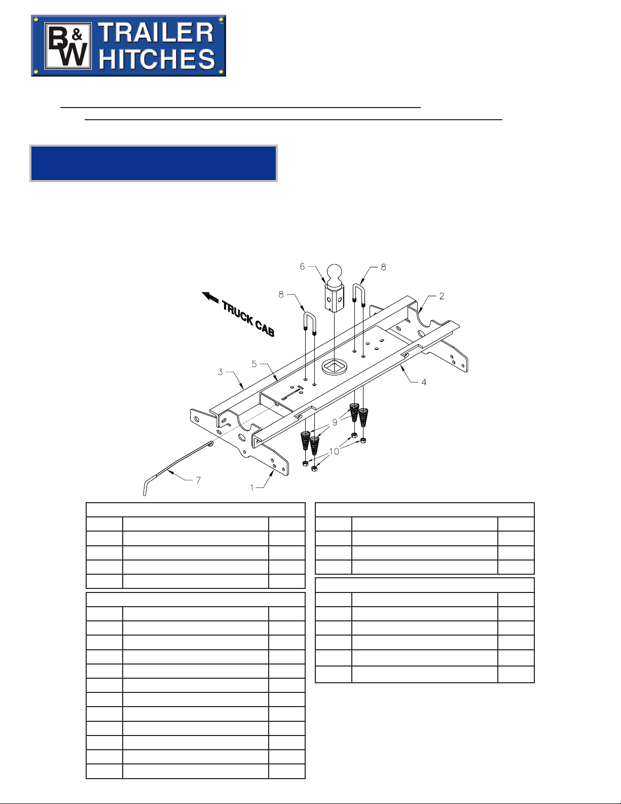
Mounting Kit Box (GNRM1197)
ITEM DESCRIPTION QTY
1 Driver Side Plate 1
2 Passenger Side plate 1
3 Front Crossmember 1
4 Rear Crossmember 1
Mounting Kit Bolt Bag
7/16” X 1-1/2 Cap Screw 4
7/16 Flat Washer 4
7/16" Lock Washer 4
7/16" Hex Nut 4
1/2” X 1-1/2” Cap Screw 10
1/2" Flat Washer 14
1/2” Lock Washer 10
1/2” Finish Nut 10
7/8” X 2-1/2” Cap Screw 2
7/8” Flat Washer 2
7/8” Lock Washer 2
7/8” Finish Nut 2
Center Box (GNRC800)
ITEM DESCRIPTION QTY
5 Center Section 1
6 2-5/16" Ball 1
7 Latch pin Handle 1
Safety Chain Kit Bolt Bag
8 1/2” U-Bolt 2
9 Conical Springs 4
10 1/2” Lock Nut 4
5/16” X 3/4” Carriage Bolt 1
5/16” X 3/4” Cap Screw 1
5/16” Lock Nut 1
Page 2

NOTICE: This product was designed to t vehicles in their original, “as manufactured” condition.
Compatibility with vehicles having replacement parts, or other modications is not guaranteed. Inspect
vehicle for modications before installation of this product.
BEFORE INSTALLING
OVERHEAD LIFTING DEVICE
An overhead-lifting device, such as chain falls, engine hoist, or cable come-a-long, can be used to lift the
center section of the hitch in place. Lower a loop of rope or chain through the 4” hole in the truck bed
oor and attach it to the latch pin in the round hitch receiver tube in the center section. Use the lifting
device to raise the center section until the round hitch receiver tube that protrudes from the center sec-
tion ts in the 4” hole in the truck bed oor. Maintaining upward pressure may facilitate fastening the
crossmember to the center section, especially if the truck bed oor has been distorted downward from
heavy use. If you use an overhead-lifting device, it should be disconnected before squaring the center
section across the frame, installing the sideplates and torquing fasteners.
WARNING
Most trucks have FUEL LINES and/or BRAKE LINES and/or ELECTRICAL WIRES located along the frame
rails where B&W Turnoverball™ hitches install. Carefully examine the location of fuel lines, brake lines
and electrical wires BEFORE INSTALLATION. Be certain you will not damage fuel lines, brake lines or
electrical wires when positioning hitch components, drilling holes, tightening fasteners, and lifting and
lowering the truck bed. The fuel tank vent, located on top of the gas tank, can be easily damaged during
the installation of the hitch components. Care must be taken when positioning the front crossmember
and center section components. We recommend removing the bed bolts on the driver’s side and lifting
the bed to give you more clearance during installation of the hitch parts under the bed oor.
WARNING
ON SHORT BED TRUCKS, BEFORE INSTALLING THIS HITCH, CHECK FOR ADEQUATE TURNING CLEARANCE BETWEEN
THE FRONT OF ALL OF YOUR TRAILERS AND THE TRUCK CAB.
WARNING
DO NOT INVERT THE BALL IN THE SOCKET WHEN CARRYING HEAVY LOADS ON 2 WHEEL DRIVE TRUCKS. THE
BALL MAY HIT THE TOP OF THE DIFFERENTIAL. REMOVE THE BALL FROM THE SOCKET BEFORE LOADING. A PLUG
FOR THE SOCKET IS AVAILABLE FROM B&W.
INSTALLATION INSTRUCTIONS
STEP ONE
Mark a 4” round hole on the topside of the truck bed oor. Center the hole between the wheel wells and
46 1/2 “ to the center of the hole from the back edge of the truck bed (tail gate end). This will place the
Turnoverball™ hitch about 6” forward of the truck axle center. Drill a small hole inside the area marked
and cut out the round hole, using a 4” hole saw or use a saber saw and metal cutting blade.
STEP 2
Select the rear crossmember that is notched on one side. With the long (2 ½”) side of the angle iron
pointing down and the short (2”) side with the notches facing the rear of the truck, position it across the
top of the frame rails, between the bed and frame, by pushing it through the opening in the wheel well on
the driver’s side of the truck. Make certain that the notches t tightly against the truck bed crossmember
on the back of the truck. Select the second crossmember without notches and place it between the bed
and frame, by pushing it through the opening in the wheel well on the driver’s side of the truck. With
the two crossmembers approximately parallel, position them about 9” apart, equally spaced in front and
behind the hole in the truck bed oor and hanging over the same distance on each side of the frame rails.
Page 3
STEP 3
With the latch pin mechanism on the driver’s side of the truck, raise the center section of the hitch into position between the crossmembers from beneath the truck. The round tube hitch receiver that protrudes from
the center section must t through the hole in the truck bed oor. Fasten the center section to the crossmembers, as shown in Fig. A, using the six ½” x 1 ½” bolts. Start these bolts through the slots in the cross-
member using a at washer and lock washer on each bolt. Align the assembly with frame rails and tighten.
STEP 4
Square the assembled center section and crossmembers across the frame. Install the sideplates on the out-
side of the frame rails by attaching the sideplates to the crossmembers using ½” x 1 ½” bolts, at washer,
lock washer and nut. Do not fully tighten. Attach the sideplate to the frame utilizing 7/8” X 2 ½” bolt and the
7/16” X 1 ½” bolts provided in the mounting kit. Repeat steps on opposite side. On some frames it may be
necessary to drill the 7/16” hole. Drill one of the 3 holes at the rear of the sideplate, taking care to avoid the
fuel line, brake line and electrical wires located on the inside of the frame. With the crossmembers, center
section and sideplates installed, torque all fasteners to 90 ft. lbs., in the following sequence. (Use caution
not to damage the brake line or fuel line). First, torque the crossmembers to the center section. Second,
torque the crossmembers to the sideplates. Third, torque the sideplates to the frame rails.
STEP 5
To install the safety chain brackets it is necessary to drill four ½” holes through the truck bed oor. Drill the
holes from beneath the truck, through the four holes furthest from the round hitch receiver tube in the cen-
ter section. Drop a U-bolt through each pair of holes from the topside of the truck bed oor. Place a spring
and lock nut on each of the four legs. Tighten the lock nuts until ¼” of thread extends through the lock nut.
STEP 6 – INSTALL LATCH PIN RELEASE HANDLE
WARNING: LATCH PIN WILL NOT FUNCTION PROPERLY IF HANDLE IS NOT INSTALLED CORRECTLY.
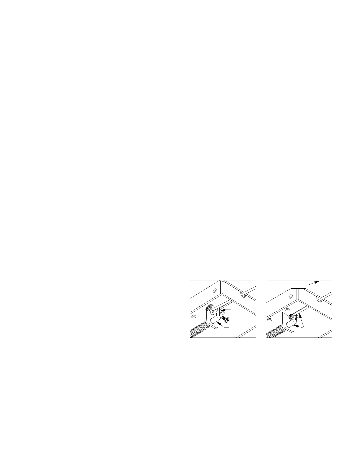
Install the latch pin release handle by inserting it through the slot in the end of the center section on the
driver’s side of the truck. Align the handle eyelet with the square hole in the latch pin so the handle is in
line with the latch pin as shown. Secure the handle to the pin with the 5/16 X 3/4” carriage bolt and 5/16”
locking ange nut as shown. Note: The included 5/16” cap screw can replace the carriage bolt if wrench
access on the “cab side” of the handle is limited. Tighten the nut until it is secure. Do not over-tighten
and deform the handle eyelet.
TAB
LATCH
PIN
STEP 7
Retract the latch pin by pulling the handle out until it stops and then rotating it slightly to the left. Place
the 2-5/16” ball in the hitch receiver. Engage the latch pin by rotating the handle slightly to the right. Be
certain the latch pin passes through the holes in the 2-5/16” ball and fully engages through both sides of
the receiver tube. Repeat this process with the 2-5/16” ball in all four positions, both upright and inverted.
Lightly lubricate the four corners of the hitch ball.
DRIVER SIDE
IN−LINE
Copyright 2014
B&W Custom Truck Beds, Inc.
ALL RIGHTS RESERVED
1197R - 05 01 2014
 Loading...