

Page 1
User Manual
1, 2, 3, 4, 5 Gas Detector
Page 2

Limited Warranty and Limitation Liability
BW Technologies LP (BW) warrants the product to be free from defects in material and workmanship under normal use and service for a period of two years,
beginning on the date of shipment to the buyer. This warranty extends only to the sale of new and unused products to the original buyer. BW’s warranty obligation is
limited, at BW’s option, to refund of the purchase price, repair or replacement of a defective product that is returned to a BW authorized service center within the
warranty period. In no event shall BW’s liability hereunder exceed the purchase price actually paid by the buyer for the Product.
This warranty does not include:
a) fuses, disposable batteries or the routine replacement of parts due to the normal wear and tear of the product arising from use;
b) any product which in BW’s opinion, has been misused, altered, neglected or damaged, by accident or abnormal conditions of operation, handling or use;
c) any damage or defects attributable to repair of the product by any person other than an authorized dealer, or the installation of unapproved parts on the
product; or
The obligations set forth in this warranty are conditional on:
a) proper storage, installation, calibration, use, maintenance and compliance with the product manual instructions and any other applicable recommendations of
BW;
b) the buyer promptly notifying BW of any defect and, if required, promptly making the product available for correction. No goods shall be returned to BW until
receipt by the buyer of shipping instructions from BW; and
c) the right of BW to require that the buyer provide proof of purchase such as the original invoice, bill of sale or packing slip to establish that the product is within
the warranty period.
THE BUYER AGREES THAT THIS WARRANTY IS THE BUYER’S SOLE AND EXCLUSIVE REMEDY AND IS IN LIEU OF ALL OTHER WARRANTIES, EXPRESS OR IMPLIED, INCLUDING BUT
NOT LIMITED TO ANY IMPLIED WARRANTY OF MERCHANTABILITY OR FITNESS FOR A PARTICULAR PURPOSE. BW SHALL NOT BE LIABLE FOR ANY SPECIAL, INDIRECT, INCIDENTAL,
OR BASED ON CONTRACT, TORT OR RELIANCE OR ANY OTHER THEORY.
Since some countries or states do not allow limitation of the term of an implied warranty, or exclusion or limitation of incidental or consequential damages, the
limitations and exclusions of this warranty may not apply to every buyer. If any provision of this warranty is held invalid or unenforceable by a court of competent
jurisdiction, such holding will not affect the validity or enforceability of any other provision.
Warranty Registration
http://www.honeywellanalytics.com/support/product-registration
Contacting BW Technologies by Honeywell
USA & Canada: 1-888-749-8878 Europe: 00800-333-222-44 Other countries: 1-403-248-9226
Bwa.customerservice@honeywell.com www.honeywellanalytics.com
Page 3

Table of Contents
Title Page
Introduction ......................................................................................................................................................................... 1
Gases Monitored ............................................................................................................................................................. 2
Safety Information - Read First.......................................................................................................................................... 2
aCautions .......................................................................................................................................................................... 3
Sensor Poisons and Contaminants .................................................................................................................................. 6
Getting Started .................................................................................................................................................................... 8
Parts of the GasAlertMicro 5/PID/IR .................................................................................................................................. 9
Screen Elements ............................................................................................................................................................... 10
Buttons .............................................................................................................................................................................. 11
Activating the
Detector ............................................................................................................................................................................. 12
Self-Tests....................................................................................................................................................................... 12
Battery Test .............................................................................................................................................................. 12
Datalogging (Optional).............................................................................................................................................. 13
Pump Test ................................................................................................................................................................ 15
Due-Lock Enabled .................................................................................................................................................... 17
Force Calibration Enabled ........................................................................................................................................ 17
Bump Daily Enabled ................................................................................................................................................. 18
Self-Test Pass ............................................................................................................................................................... 19
Self Test Fail.................................................................................................................................................................. 19
Battery Test ................................................................................................................................................................... 20
Datalogger Operation (Optional).................................................................................................................................... 20
Deactivating the Detector................................................................................................................................................. 21
i
Page 4

GasAlertMicro 5/PID/IR
User Manual
Title Page
User Options Menu ........................................................................................................................................................... 21
Exit User Options Menu ................................................................................................................................................. 22
Options Menu................................................................................................................................................................. 22
Backlight ................................................................................................................................................................... 23
Confidence Beep ...................................................................................................................................................... 23
Due-Lock .................................................................................................................................................................. 23
Latched Alarms......................................................................................................................................................... 24
Passcode Protect...................................................................................................................................................... 24
Safe Display.............................................................................................................................................................. 25
Sensor Configuration ..................................................................................................................................................... 25
Sensor Enable/Disable ............................................................................................................................................. 26
Span Gas Value........................................................................................................................................................ 27
STEL Period ............................................................................................................................................................. 28
TWA Method ............................................................................................................................................................. 28
Resolution................................................................................................................................................................. 29
%Vol CO
%Vol CH
(CO2 Sensors Only)................................................................................................................................. 29
2
(LEL Sensors Only).................................................................................................................................. 30
4
Correction Factor (CF) .............................................................................................................................................. 30
Logger Option ................................................................................................................................................................ 33
Clock Option .................................................................................................................................................................. 33
Language Selection ....................................................................................................................................................... 34
Tech Mode ..................................................................................................................................................................... 35
Sensors..................................................................................................................................................................... 36
Initialize ..................................................................................................................................................................... 37
Force Calibration ...................................................................................................................................................... 37
Bump Daily ............................................................................................................................................................... 38
Stealth Mode............................................................................................................................................................. 38
ii
Page 5

GasAlertMicro 5/PID/IR
User Manual
Title Page
Sleep Mode............................................................................................................................................................... 39
Alarms ................................................................................................................................................................................ 40
Gas Exposures Computed ............................................................................................................................................. 43
Viewing Gas Exposures ................................................................................................................................................. 43
Clearing Gas Exposures ................................................................................................................................................ 44
Gas Alarm Setpoints ...................................................................................................................................................... 44
Viewing the Alarm Setpoints .......................................................................................................................................... 44
Resetting Gas Alarm Setpoints ...................................................................................................................................... 45
Stopping a Gas Alarm .................................................................................................................................................... 46
Sensor Alarm ................................................................................................................................................................. 46
Pump Alarm ................................................................................................................................................................... 46
Low Battery Alarm.......................................................................................................................................................... 47
Automatic Deactivation Alarm ........................................................................................................................................ 47
Bump Test.......................................................................................................................................................................... 47
Performing a Bump Test ................................................................................................................................................ 47
Calibration and Setting Alarm Setpoints ........................................................................................................................ 48
Guidelines ...................................................................................................................................................................... 48
Diagnostics Testing........................................................................................................................................................ 49
Applying Gas to the Sensors ......................................................................................................................................... 50
Single Gas Calibration Cap ...................................................................................................................................... 50
Calibration Procedure .................................................................................................................................................... 51
Start Calibration ........................................................................................................................................................ 52
Auto Zero and Oxygen (O
Zero CO
(GasAlertMicro 5 IR only) ......................................................................................................................... 52
2
) Sensor Calibration ....................................................................................................... 52
2
Passcode Protect Activated ...................................................................................................................................... 53
Auto Span ................................................................................................................................................................. 54
Successful Span ....................................................................................................................................................... 56
iii
Page 6

GasAlertMicro 5/PID/IR
User Manual
Title Page
Setting the Calibration Due Date .............................................................................................................................. 57
Alarm Setpoints ........................................................................................................................................................ 58
Setting the Remaining Alarm Setpoints .................................................................................................................... 60
Finish Calibration ...................................................................................................................................................... 60
Verification ................................................................................................................................................................ 61
Unsuccessful Span ................................................................................................................................................... 61
Pump .................................................................................................................................................................................. 64
....................................................................................................................................................................................... 64
Identifying the Pump ...................................................................................................................................................... 64
Generation 1: 116885-L3 (yellow) and 118933-L3 (black)........................................................................................ 64
Generation 2: 130916-L3 (yellow) and 130917-L3 (black)........................................................................................ 65
Installing the Pump Module ............................................................................................................................................. 66
Replacing the Pump Filter (Generation 2 Pump) ........................................................................................................... 67
Replacing the Pump Nozzle (Generation 2 Pump) ........................................................................................................ 68
Attaching the Auxiliary Filter .......................................................................................................................................... 68
Confined Space Sampling ............................................................................................................................................. 70
Maximum Hose Length when Confined Space Sampling......................................................................................... 71
Datalogger ......................................................................................................................................................................... 72
MMC/SD Card Compatibility............................................................................................................................................. 72
Inserting the MMC/SD Card ........................................................................................................................................... 72
MMC/SD Card Troubleshooting ....................................................................................................................................... 73
Restoring Datalog Files.................................................................................................................................................. 74
Reformatting the MMC/SD Card .................................................................................................................................... 75
Import Datalogs to Fleet Manager II ................................................................................................................................ 76
Minimum PC Requirements ........................................................................................................................................... 76
Importing from MicroDock II to Fleet Manager II............................................................................................................ 76
Import to Fleet Manager II Using a Card Reader ........................................................................................................... 76
iv
Page 7

GasAlertMicro 5/PID/IR
User Manual
Title Page
View Datalog Files in Spreadsheets ................................................................................................................................ 77
Example of a Datalog Spreadsheet .......................................................................................................................... 78
Maintenance ...................................................................................................................................................................... 81
Battery Cautions ........................................................................................................................................................... 81
Charging the Battery ...................................................................................................................................................... 81
Replacing the Alkaline Batteries .................................................................................................................................... 82
Replacing the Lithium Battery Pack ............................................................................................................................... 83
Replacing a Sensor or Sensor Filter .............................................................................................................................. 83
Photoionization Detector (PID) ...................................................................................................................................... 85
Clean or Replace the Lamp ...................................................................................................................................... 85
Replace the Lamp..................................................................................................................................................... 86
Replace the Electrode Stack .................................................................................................................................... 87
WEEE Battery Directive ................................................................................................................................................. 87
Removal and Disposal of the Battery Pack............................................................................................................... 87
Removal and Disposal of the Coin Cell .................................................................................................................... 87
Troubleshooting................................................................................................................................................................ 89
Replacement Parts and Accessories .............................................................................................................................. 95
Specifications.................................................................................................................................................................... 97
General Specifications for Datalogger Units ................................................................................................................ 100
GasAlertMicro 5/PID/IR Downloadable Datalogger ..................................................................................................... 101
PID Correction Factor (CF) Library................................................................................................................................ 102
v
Page 8

GasAlertMicro 5/PID/IR
User Manual
Title Page
vi
Page 9

List of Figures
Figure Title Page
1. Parts of the GasAlertMicro 5/PID/IR...................................................................................................................... 9
2. Screen Elements ................................................................................................................................................. 10
3. Applying Gas to the Sensors ............................................................................................................................... 50
4. Single Gas Calibration Cap ................................................................................................................................. 51
5. Removing the Single Gas Calibration Cap .......................................................................................................... 51
6. Installing the Pump Module ................................................................................................................................. 66
7. Replacing the Pump Filter (Generation 2 Pump)................................................................................................. 67
8. Replacing the Pump Nozzle ................................................................................................................................ 68
9. Attaching the Auxiliary Filter ............................................................................................................................... 68
10. Attaching the Filter Cord..................................................................................................................................... 69
11. Attaching the Sample Probe................................................................................................................................ 70
12. Inserting/Removing the MMC/SD Card ............................................................................................................... 73
13. Replacing the Alkaline Batteries.......................................................................................................................... 82
14. Replacing the Lithium Battery Pack .................................................................................................................... 83
15. Replacing a Sensor or Sensor Filter ................................................................................................................... 84
16. Parts of the PID ................................................................................................................................................... 86
vii
Page 10

GasAlertMicro 5/PID/IR
User Manual
viii
Page 11

List of Tables
Table Title Page
1. Gases Monitored ................................................................................................................................................... 2
2. Sensor Poisons and Contaminants ....................................................................................................................... 6
3. International Symbols ............................................................................................................................................ 7
4. Parts of the GasAlertMicro 5/PID/IR...................................................................................................................... 9
5. Screen Elements ................................................................................................................................................. 10
6. Button .................................................................................................................................................................. 11
7. Alarms ................................................................................................................................................................. 40
8. Computed Gas Exposures .................................................................................................................................. 43
9. Gas Alarm Setpoints ........................................................................................................................................... 44
10. OSHA Sample Factory Alarm Setpoints.............................................................................................................. 45
11. Applying Gas to the Sensors ............................................................................................................................... 50
12. Single Gas Calibration Cap ................................................................................................................................. 51
13. Time Required to Span ....................................................................................................................................... 55
14. Installing the Pump Module ................................................................................................................................. 66
15. Generation 1 Pump Maximum Hose Length ....................................................................................................... 71
16. Generation 2 Pump Maximum Hose Length ....................................................................................................... 71
17. Datalog Spreadsheet Example............................................................................................................................ 78
18. Datalog Status Codes ......................................................................................................................................... 79
19. Datalog Gas and Correction Factor Sensor Codes ............................................................................................. 80
20. Replacing the Alkaline Batteries.......................................................................................................................... 82
21. Replacing a Sensor or Sensor Filter .................................................................................................................. 85
22. Parts of the PID sensor ....................................................................................................................................... 85
23. Troubleshooting................................................................................................................................................... 89
ix
Page 12

GasAlertMicro 5/PID/IR
User Manual
24. Replacement Parts and Accessories .................................................................................................................. 95
25. PID Corrections Factor (CF) Library.................................................................................................................. 102
x
Page 13

ISO 9001
GasAlertMicro 5/PID/IR
Introduction
GasAlertMicro 5/PID/IR
Introduction
a Warning
To ensure personal safety, read the Safety Information -
Read First and Cautions before using the detector.
The GasAlertMicro 5, GasAlertMicro 5 PID, and GasAlertMicro 5 IR
gas detectors (“the detector”) warn of hazardous gas at levels above
user-defined alarm setpoints.
The detector is a personal safety device. It is your responsibility to
respond properly to the alarm.
Note
Unless reference is made to a specific detector model, the
GasAlertMicro 5, GasAlertMicro 5 PID, and GasAlertMicro 5 IR
detectors are referred to as GasAlertMicro 5/PID/IR.
Refer to Gases Monitored
prior to operating the detector.
1
Page 14

GasAlertMicro 5/PID/IR
User Manual
Gases Monitored
The following table lists the gases that are monitored by the detector.
Table 1. Gases Monitored
Gas Detected Unit of Measure
Oxygen (O2)
Combustible gases (LEL)
Carbon monoxide (CO) parts per million (ppm)
Hydrogen sulfide (H
Phosphine (PH
Sulfur oxide (SO
Chlorine (Cl
)
2
Ammonia (NH
Nitrogen dioxide (NO
S)
2
)
3
)
2
)
3
)
2
Hydrogen cyanide (HCN) parts per million (ppm)
Chlorine dioxide (ClO
Ozone (O
)
3
)
2
Volatile organic compounds
(VOC)
Carbon dioxide (CO
) parts per million or %vol CO
2
% volume
a) percent of lower explosive
limit (%LEL)
b) percent by volume
methane 0-5.0% v/v
parts per million (ppm)
parts per million (ppm)
parts per million (ppm)
parts per million (ppm)
parts per million (ppm)
parts per million (ppm)
parts per million (ppm)
parts per million (ppm)
parts per million (ppm)
CAUTION: FOR SAFETY REASONS, THIS EQUIPMENT MUST BE
OPERATED AND SERVICED BY QUALIFIED PERSONNEL ONLY.
READ AND UNDERSTAND THIS USER MANUAL COMPLETELY
BEFORE OPERATING AND SERVICING.
Safety Information - Read First
Use the detector only as specified in this user manual, otherwise the
protection provided by the detector may be impaired.
International symbols used on the detector and in this user manual are
defined in Table 3.
Read the Cautions on the following pages before using the detector.
ec Warning
This instrument contains batteries. Do not mix with the
solid waste stream. Spent batteries must be disposed of
by a qualified recycler or hazardous materials handler.
Dispose of lithium cells immediately. Do not
disassemble and do not dispose of in fire. Do not mix
with the solid waste stream. Spent batteries must be
disposed of by a qualified recycler or hazardous
materials handler.
2
2
Page 15

GasAlertMicro 5/PID/IR
aCautions
aCautions
• Warning: Substitution of components may impair Intrinsic
Safety.
• Caution: For safety reasons, this equipment must be
operated and serviced by qualified personnel only. Read
and understand this user manual completely before
operating or servicing.
• Do not use the detector if it is damaged. Inspect the
detector before using. Look for cracks and/or missing parts.
• If the detector is damaged or parts are missing, contact BW
Technologies by Honeywell immediately.
• Use only sensor(s) that are specifically designed for the
GasAlertMicro 5/PID/IR detectors. Refer to Replacement
Parts and Accessories.
• Calibrate the detector before first-time use and then on a
regular schedule, depending on use and sensor exposure
to poisons and contaminants. Sensors must be calibrated
regularly and at least once every 180 days (6 months).
• BW recommends to bump test the sensors, before each
day’s use, to confirm their ability to respond to gas by
exposing the detector to a gas concentration that exceeds
the alarm setpoints. Manually verify that the audible and
visual alarms are activated. Calibrate if the readings are not
within the specified limits.
• BW recommends the combustible sensor be checked with a
known concentration of calibration gas after any known
exposure to catalyst contaminants/poisons (sulfur
compounds, silicon vapors, halogenated compounds, etc).
• The combustible sensor is factory calibrated to 50% LEL
methane. If monitoring a different combustible gas in the %
LEL range, calibrate the sensor using the appropriate gas.
• Warning: High off-scale LEL readings may indicate an
explosive concentration.
• Only the combustible gas detection portion of this
instrument has been assessed for performance by CSA
International.
• Protect the combustible sensor from exposure to lead
compounds, silicones, and chlorinated hydrocarbons.
Although certain organic vapors (such as leaded gasoline
and halogenated hydrocarbons) may temporarily inhibit
sensor performance, in most cases, the sensor will recover
after calibration.
aCautions
• Before using common products around sensors, refer to
Sensor Poisons and Contaminants
• High concentrations of certain toxic gases, for example
H2S, may have an adverse effect on the LEL sensor. This
effect, known as inhibition, is usually temporary but in
extreme circumstances can impair the sensitivity of the LEL
sensor.
After any gas exposure that causes an alarm in the toxic
gas sensors, the LEL sensor should be verified with a bump
test, and recalibrated if necessary.
• Any rapid up-scaling reading followed by a declining or
erratic reading may indicate a gas concentration beyond
upper scale limit, which may be hazardous.
.
3
Page 16

GasAlertMicro 5/PID/IR
User Manual
• Calibrate only in a safe area that is free of hazardous gas, in
an atmosphere of 20.9% oxygen.
• Use only BW approved batteries for the GasAlertMicro 5/
PID/IR detectors. Refer to Replacement Parts and
Accessories.
• Charge the detector before first-time use. BW recommends
the detector be charged after every workday.
• Charge the battery pack immediately when a low battery
alarm occurs.
• Read and adhere to the battery cautions provided in Battery
Cautions.
• Charge the GasAlertMicro 5/PID/IR batteries using the
recommended charging adapter only. Do not use any other
charging adapter. Failure to adhere to this caution can lead
to fire and/or explosion.
• Read and adhere to all instructions in the charger user
manual. Failure to do so can result in fire, electrical shock,
personal injury, and/or property damage.
• Extended exposure of the GasAlertMicro 5/PID/IR detectors
to certain concentrations of combustible gases and air may
stress a detector element, which can seriously affect its
performance. If an alarm occurs due to high concentration
of combustible gases, recalibration should be performed, or
if needed, the sensor replaced.
aCautions
• Protect the PID sensor from exposure to silicone vapors.
• When calibrating O
the Toxic 2 sensor position, a single gas calibration cap
must be used to ensure accurate calibration. For more
information, refer to Single Gas Calibration Cap
• Replace the CO
area that is free of hazardous gas.
• The optional pump (M5-PUMP) is certified for use with the
GasAlertMicro 5/PID/IR detectors only.
• Do not immerse the detector in liquids.
• Do not test the combustible sensor’s response with a
butane cigarette lighter; doing so will damage the sensor.
• Do not expose the detector to electrical shock or severe
continuous mechanical shock.
• Do not attempt to disassemble, adjust, or service the
detector unless instructions for that procedure are provided
in the user manual and/or that part is listed as a
replacement part. Use only BW Technologies by Honeywell
Replacement Parts and Accessories
• The detector warranty is void if customer, personnel, or
third parties damage the detector during repair attempts.
Repair attempts made by non-BW Technologies by
Honeywell repair/service personnel voids this warranty.
Lithium Battery Packs
• Warning: The lithium battery (M5-BAT08) may present a risk
of fire or chemical burn hazard if misused. Do not
disassemble,
heat above 100°C (212°F), or incinerate.
and ClO2 sensors that are located in
3
sensor only in a safe and non-hazardous
2
.
.
4
Page 17

• Do not use any other lithium batteries with the
GasAlertMicro 5/PID/IR detectors. Use of any other cell can
cause fire and/or explosion. To order and replace the M5BAT08 battery, refer to Replacement Parts and Accessories.
• Warning: Lithium polymer cells exposed to heat at 130°C
(266°F) for 10 minutes can cause fire and/or explosion.
• Dispose of used lithium cells immediately. Do not
disassemble and do not dispose of in fire. Do not mix with
the solid waste stream. Spent batteries must be disposed
of by a qualified recycler or hazardous materials handler.
• Keep lithium cells away from children.
• Products may contain materials that are regulated for
transportation under domestic and international dangerous
goods regulations. Return product in compliance with
appropriate dangerous goods regulations. Contact freight
carrier for further instructions.
GasAlertMicro 5/PID/IR
aCautions
5
Page 18

GasAlertMicro 5/PID/IR
User Manual
Sensor Poisons and Contaminants
Several cleaners, solvents, and lubricants can contaminate and cause
permanent damage to sensors. Before using cleaners, solvents, and
lubricants in close proximity to the detector sensors, read and adhere
to the following caution and table.
a Caution
Use only the following BW Technologies by Honeywell
recommended products and procedures:
• Use water based cleaners.
• Use non-alcohol based cleaners.
• Clean the exterior with a soft, damp cloth.
• Do not use soaps, polishes, or solvents.
The following table lists common products to avoid using around
sensors.
Table 2. Sensor Poisons and Contaminants
Cleaners and
Lubricants
Brake cleaners Silicone cleaners
Lubricants Silicone based
Rust inhibitors Hand/body and
Window and glass
cleaners
Dishsoaps Mold releasing
Citrus based cleaners Polishes
Alcohol based
cleaners
Hand sanitizers
Anionic detergents
Methanol
(fuels and antifreezes)
Silicones Aerosols
Bug repellents
and protectants
adhesives, sealants, and gels
medicinal creams
that contain silicone
Tissues containing
silicone
agents
and sprays
Lubricants
Rust inhibitors
Window and
glass cleaners
6
Page 19

Table 3. International Symbols
Symbol Description
GasAlertMicro 5/PID/IR
Sensor Poisons and Contaminants
n
g
X
ATEX
IECEx
EAC Ex
Approved to both U.S. and Canadian Standards by CSA International
European Explosives Protection
Conforms to European Union Directives
Conforms to European ATEX Directives
International Electrotechnical Commission Scheme for Certification to Standards for Electrical Equipment for
Explosive Atmospheres
Conforms to Russian Custom Union Certification and Declaration
Conforms to Korea Testing Laboratory (KTL) Certification
Conforms to Brazilian InMetro Certification
Australian Regulatory Compliance Mark
7
Page 20

GasAlertMicro 5/PID/IR
User Manual
Getting Started
The list below provides the standard items included with the detector.
If the detector is damaged or parts are missing, contact the place of
purchase immediately.
• Batteries: Three replaceable alkaline cells with battery pack, or
one rechargeable lithium battery pack
• Sensors: O
PID, or CO
• Calibration cap and hose
• Single gas calibration cap
• Screwdriver
• Quick reference guide
• Quick reference card
• Technical Reference Guide and training on CD-ROM
• Fleet Manager II (if applicable)
To order parts, refer to Replacement Parts and Accessories
, combustible (LEL), toxic, H2S/CO (TwinTox sensor),
2
2
.
The detector is shipped with the sensors, and battery packs installed.
To replace sensors, the pump, or the battery pack, refer to Replacement
Parts and Accessories.
To become oriented with the features and functions of the detector, refer
to the following figures and tables:
• Figure 1.
• Figure 2. and Table 5. describe the detector’s screen elements.
• Table 6.
and Table 4. describe the detector’s components.
describes the detector’s button.
8
Page 21
GasAlertMicro 5/PID/IR
Parts of the GasAlertMicro 5/PID/IR
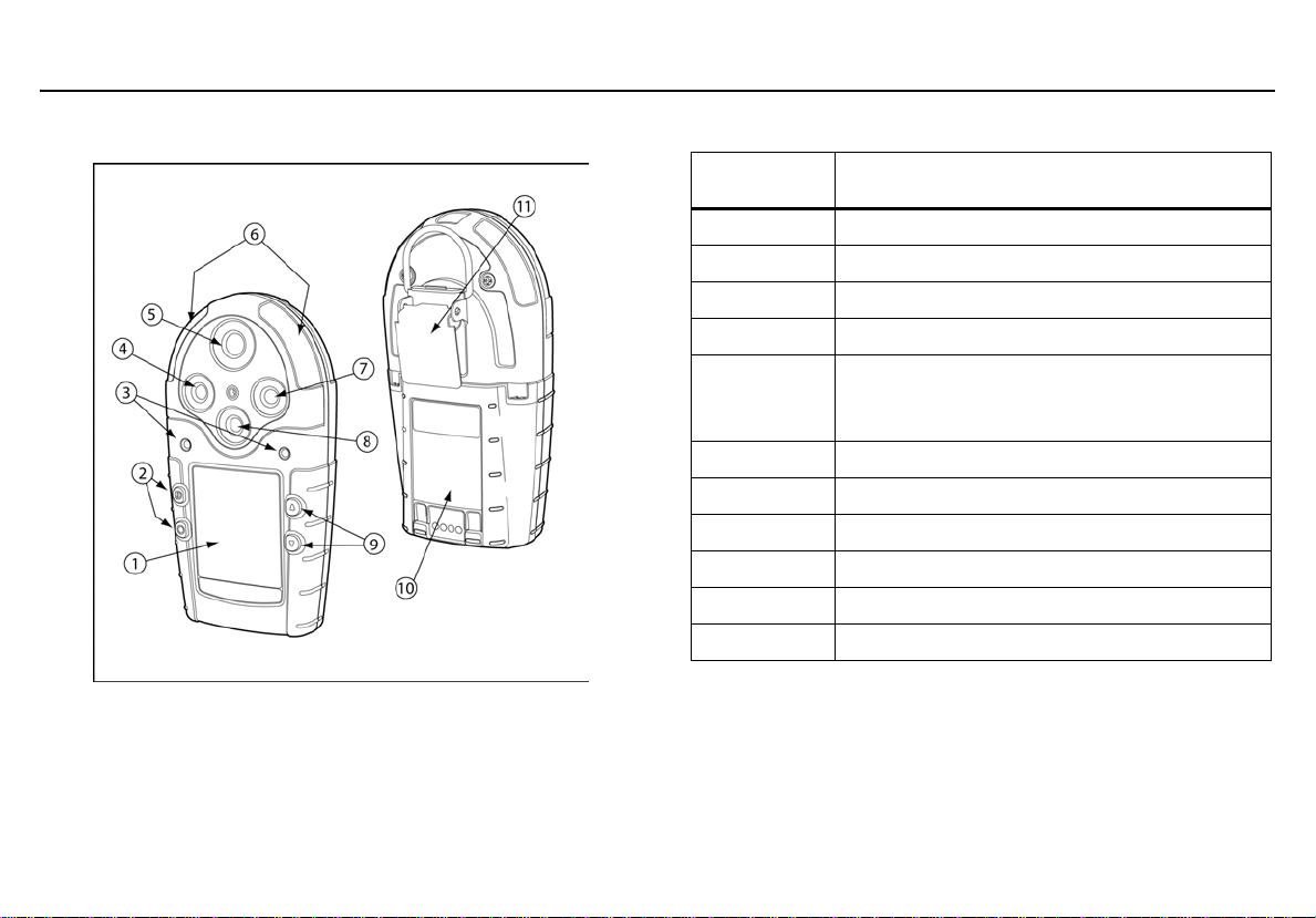
Parts of the GasAlertMicro 5/PID/IR
Figure 1. Parts of the GasAlertMicro 5/PID/IR
Table 4. Parts of the GasAlertMicro 5/PID/IR
Item Description
1 Liquid crystal display (LCD)
2 Buttons
3 Audible alarms
4 Toxic 2 sensor
Toxic 1/PID sensor (GasAlertMicro 5 PID)
5
6 Visual alarm indicators (LEDs)
7 LEL sensor
8 Oxygen sensor
9 Buttons
10 Battery pack
11 Alligator clip
or
Toxic 1/IR (CO
) sensor (GasAlertMicro 5 IR)
2
9
Page 22
GasAlertMicro 5/PID/IR
User Manual
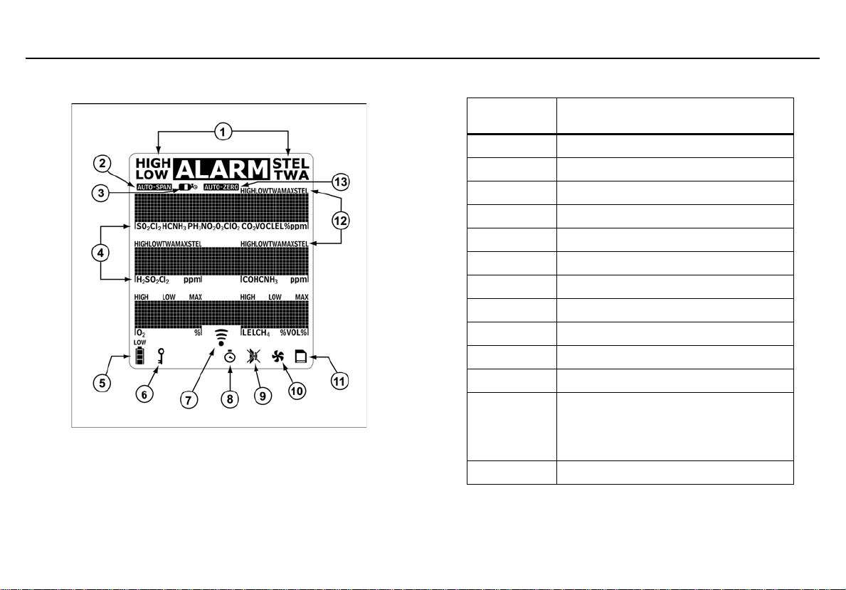
Screen Elements
Figure 2. Screen Elements
Note
If enabled, the backlight automatically activates for 8 seconds
when there is an alarm condition and whenever there is
insufficient light to view the LCD. Any but ton reactivates the
backlight in low light conditions.
Table 5. Screen Elements
Item Description
1 Alarm condition
2 Automatically span sensor
3 Gas cylinder
4Gas type
5 Battery life indicator
6 Passcode lock
7 Data transmission
8Clock
9 Stealth mode
10 Pump indicator (optional)
11 MMC indicator (optional)
Alarm condition (low, high, TWA,
12
13 Automatically zero sensor
STEL, or multi alarm) or view TWA,
STEL and peak (MAX) gas exposures
10
Page 23

GasAlertMicro 5/PID/IR
Buttons
Buttons
Button Description
A
G
H
C
Table 6. Button
• To activate the detector press A.
• To deactivate the detector, press and hold A until the countdown is complete.
• To increment the displayed value or scroll up, press G.
• To enter the user options menu, press and hold G and H simultaneously until the countdown is complete.
• To clear the TWA, STEL, and peak (MAX) gas exposure readings, press and hold C and G simultaneously
until the countdown is complete.
• To view the date and time, alarm setpoints (TWA, STEL, low, high) of all sensors, and the LEL/PID correction factor
(if applicable) press G.
• To decrement the displayed value or scroll down, press H.
• To initiate calibration and to define alarm setpoints, press and hold C and H simultaneously until the countdown
is complete.
• To view the TWA, STEL, and peak (MAX) gas exposure readings, press C.
• To acknowledge latched alarms, press C. Refer to
Latched Alarms on page 24.
11
Page 24
GasAlertMicro 5/PID/IR
User Manual
Activating the Detector
If using the pump module, attach it and the pump accessories prior to
activating the detector.
For illustrations and procedures, refer to the following:
.
•
• Confined Space Sampling
• Replacing the Pump Filter (Generation 2 Pump)
• Replacing the Pump Nozzle (Generation 2 Pump)
• Attaching the Auxiliary Filter
Note
Only activate the detector in a safe atmosphere that is free of
hazardous gas in an atmosphere of 20.9% oxygen.
To activate the detector, press A.
Self-Tests
When the detector is activated, it performs several self-tests. Confirm
the following tests occur.
Note
If an error message displays during the self-test, refer to
Troubleshooting
.
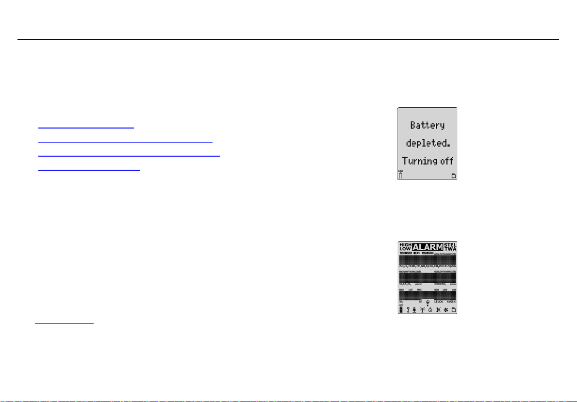
Battery Test
The detector performs a battery test during startup. If the battery has
insufficient power to operate, the following screen displays before
deactivating.
Replace the batteries and reactivate the detector.
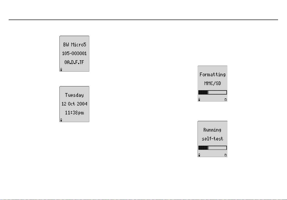
1. All of the LCD elements display simultaneously as the detector beeps, flashes, vibrates, and briefly activates the backlight.
12
Page 25
GasAlertMicro 5/PID/IR
Activating the Detector
2. The version and serial number of the detector displays.
3. The date and time displays.
Datalogging (Optional)
4. If the detector is a datalogging unit, it determines if
• a MultiMediaCard (MMC) or Secure Digital (SD) card is
inserted,
• the detector can communicate with the card,
• the detector supports the size of the card, and
• the card requires formatting.
Note
If there is a problem with the MMC/SD card, Datalogger
disabled displays. The detector then automatically continues
with the self-test.
If the card requires formatting, the following screen
displays as the card is automatically formatted.
5. The detector then runs a self-test to verify the sensors and power supply are operating correctly.
13
Page 26
GasAlertMicro 5/PID/IR
User Manual
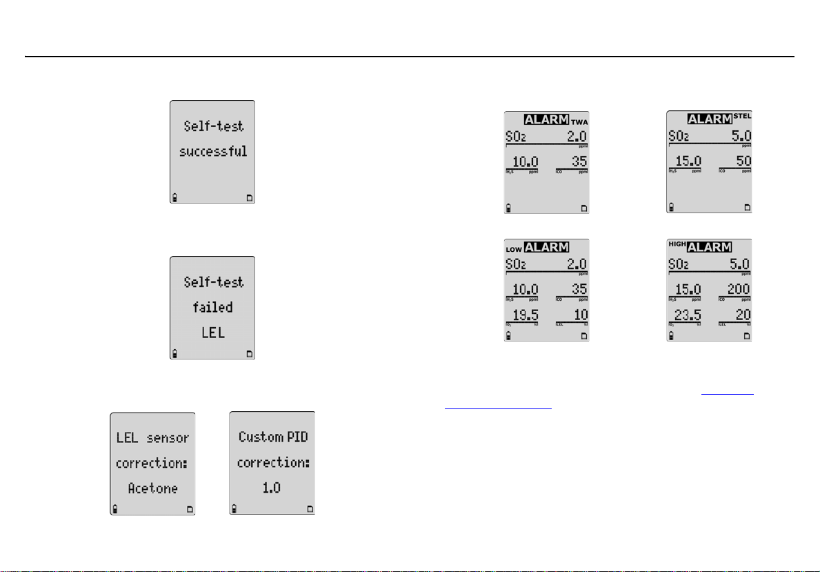
Self-test Successful: If successful, the following screen displays.
Self-test Unsuccessful: If a sensor fails the self-test, a warning
displays indicating which sensor(s) has failed.
6. If correction factors are set in the user options, the LEL or PID (custom) correction factors display.
7. The TWA, STEL, low, and high alarm setpoints then display in the following order (left to right).
TWA STEL
Low High
Note
The alarm setpoints may vary by region. Refer to Resetting
Gas Alarm Setpoints.
14
Page 27
Pump Test
a Warning
If the pump module is installed on the detector, the
following three things must occur during start-up. If any
one of the conditions below does not occur, discontinue
use of the detector and contact BW Technologies by
Honeywell immediately.
• The detector prompts for a pump test during start-up
• The pump module passes the pump test at start-up when
the pump inlet or sample chain inlet is blocked
•The J icon displays on the LCD
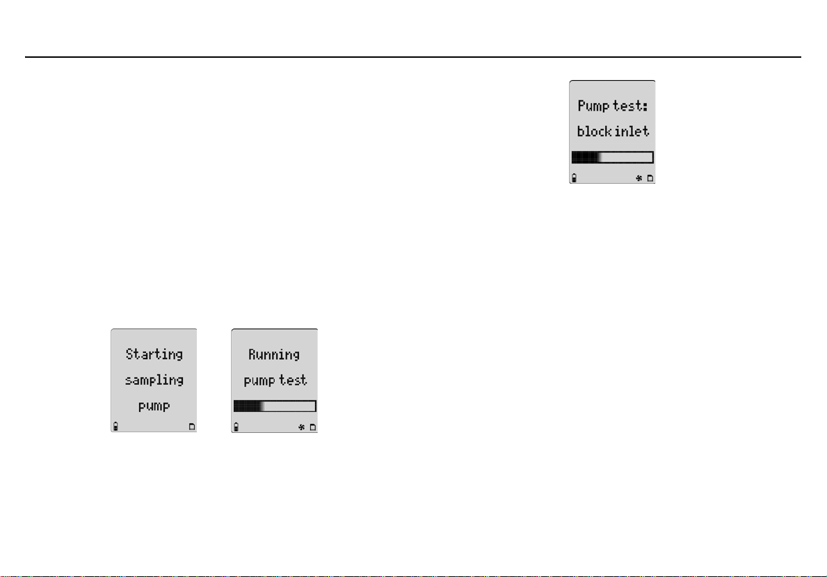
8. If the pump module is attached to the detector, the following screens display.
GasAlertMicro 5/PID/IR
Activating the Detector
When the following screen displays, block the pump inlet.
15
Page 28
GasAlertMicro 5/PID/IR
User Manual
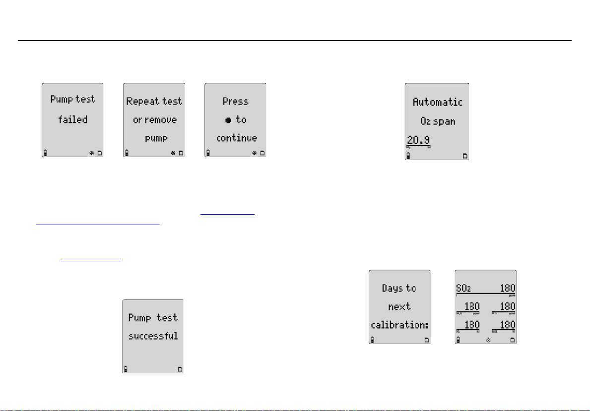
If the pump inlet is not blocked within 10 seconds or the pump
test fails, the following screens display.
If C is not pressed or the pump is not removed within
25 seconds, the detector performs the pump test again.
Note
The pump may require a new filter. Refer to Replacing the
Pump Filter (Generation 2 Pump).
If the pump alarm persists, remove the battery pack to deactivate the detector and then refer to the “Pump Operation” section of Troubleshooting
.
If the pump test is successful, the following screen
displays and the self-test continues.
9. Unless disabled in user options, the oxygen (O
) sensor is cali-
2
brated automatically.
If the calibration is successful, the detector beeps twice.
Note
If the automatic O
Automatic O
calibration feature has been disabled,
2
span disabled displays.
2
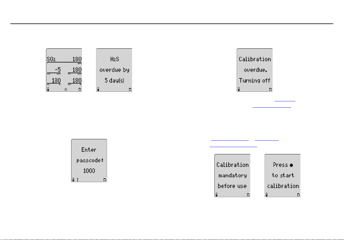
10. The number of days remaining before calibration is due displays for all sensors.
16
Page 29
GasAlertMicro 5/PID/IR
Activating the Detector
If any sensor is over due for calibration, the LCD displays the
name of the sensor and the number of days past due.
Due-Lock Enabled
The Due-lock option ensures that a passcode must be entered when
calibration is past due, otherwise the detector automatically deactivates.
11. If Due-Lock is enabled in the user options, the following
screen displays.
Enter the correct passcode and press C to confirm.
If no passcode is entered, or it is entered incorrectly, the following screen displays.
To enable/disable this option, refer to Due-Lock
options menu. Also refer to Passcode Protect
in the user
.
Force Calibration Enabled
12. If Force cal (force calibration) is enabled in tech mode, calibra-
tion is mandatory before the detector enters normal operation.
Refer to Force Calibration
refer to Calibration Procedure
in Tech Mode to enable/disable, and
to calibrate.
Note
If any sensor is overdue, Y displays continually until calib ration
is performed.
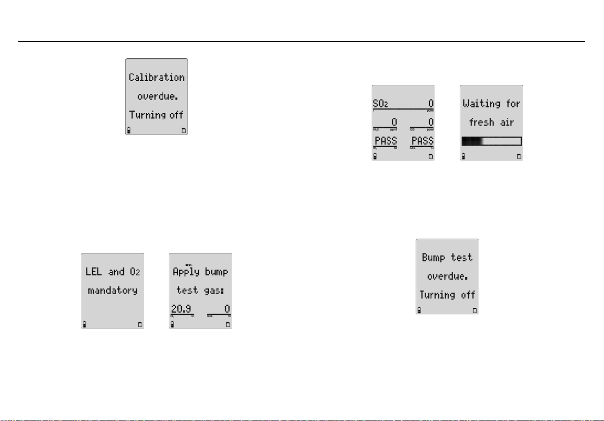
If C is not pressed to start calibration, the following screen displays and the detector deactivates.
17
Page 30
GasAlertMicro 5/PID/IR
User Manual
Successful Bump Test: If the bump test passes, the following screens
display.
Bump Daily Enabled
a Caution
BW recommends that a bump test to all sensors be
performed every 24 hours prior to the beginning of the
work shift.
13. If Bmp Daily (bump daily) is enabled in tech mode, the follow-
ing screens display.
If a bump test of the LEL and O
detector will deactivate.
Apply the LEL gas and then apply the O
percentage than the default 20.9%, such as 18% O
18
sensor is not performed, the
2
(a higher or lower
2
).
2
The detector waits for the sensor(s) to clear (30 seconds) and then
enters normal operation.
Unsuccessful Bump Test: If the bump test is unsuccessful or the bump
test is not performed, the following screen displays and the detector
deactivates.
Page 31

GasAlertMicro 5/PID/IR
Activating the Detector
If additional sensors require a bump test but are not mandatory, the
following screens display.
Press C Yes to accept and proceed to normal operation.
Or
If A No is pressed, or no buttons are pressed, the sensor(s) that is
past due displays as FAIL when the detector enters normal operation.
In the following screen example, only the SO
operational.
The self-test is now complete.
, CO, and O2 sensors are
2
Self-Test Pass
If the detector passes the self-test, it enters normal operation and
displays the ambient gas readings.
The detector begins recording the peak (MAX) gas exposure and calculating the short-term exposure level (STEL) and time-weighted average
(TWA) exposures.
Self Test Fail
If a sensor fails, FAIL flashes above that sensor on the normal operation
screen. For possible problems and solutions, refer to Troubleshooting
.
19
Page 32

GasAlertMicro 5/PID/IR
User Manual
Battery Test
The batteries are tested when the detector is activated and continuously
thereafter. The battery power icon displays continually during normal
operation. If battery power is low, flashes.
Datalogger Operation (Optional)
a Caution
Do not remove the battery pack while the detector is
activated. Doing so will prevent the datalogger from
logging correctly.
Datalogger operation is automatic and requires no settings. During
normal operation the card is tested every 20 seconds.
Note
The MMC/SD card icon (S) displays continuously on the LCD
when the card is inserted. The card is not required for operation; however, if the card is not inserted the detector will not
record data.
20
Page 33

GasAlertMicro 5/PID/IR
Deactivating the Detector
Deactivating the Detector
To deactivate the detector, press and hold A while it beeps and flashes
to the corresponding countdown.
At the end of the countdown, the detector emits an extended beep and
flash then displays 0 before deactivating.
Note
If A is not held down for the complete countdown, the detector
remains activated.
User Options Menu
If the detector is passcode protected, a passcode must be entered to
access the user options menu. For more information, refer to Passcode
Protect.
The available user options are as follows:
1. Exit
2. Options: Backlight, confidence beep, due-lock, latch, passcode, and safe mode.
3. Sensors: Sensor enable/disable, span gas, STEL period, TWA
method, resolution, % vol CH
calibration, and % vol CO
4. Logger
5. Clock
6. Language: English, French, German, Spanish, and Portuguese.
7. Tech mode: Sensors, initialize, forced calibration, daily bump
test, stealth, and zero level (CO
Tech mode is not visible in the user options menu. To access
this option, refer to Tech Mode
, correction factor, automatic O2
4
(CO2 sensor only)
2
sensor only).
2
Note
.
21
Page 34

GasAlertMicro 5/PID/IR
User Manual
1. To enter the user options menu, press and hold G and H
simultaneously as the detector beeps and flashes to the corresponding countdown.
H must be held down for the entire countdown to
G and
access the user options menu.
When the countdown is complete, the revision/serial number
screen displays followed by the options menu.
2. To scroll through the options, press H or G. When the cursor displays beside the desired option, press C.
3. To return to the previous menu, scroll to Back and press C or press A.
Note
If no buttons are pressed within 20 seconds, the detector
returns to normal operation.
Exit User Options Menu
To exit the user options menu and return to normal operation, scroll to
Exit and press C. The following screen displays.
The user options menu can also be exited by repeatedly pressing A
until the detector returns to normal operation.
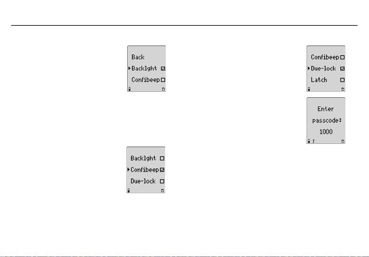
Options Menu
Each feature within the Options menu is enabled/disabled by pressing
C to toggle between the checkboxes.
Enabled
Disabled
22
Page 35
GasAlertMicro 5/PID/IR
User Options Menu
Backlight
The Backlght (backlight) option enables
the LCD backlight to activate automatically
in low-light conditions.
If disabled, the backlight activates only
when the detector is in alarm mode.
Note
In stealth mode, the backlight does
not activate.
The detector is shipped with the Backlght
option enabled.
Confidence Beep
The Confibeep (confidence beep) option
provides continuous confirmation that the
detector is operating properly. When confidence beep is enabled, the audible alarm
beeps once every 10 seconds.
Note
Confidence beep is automatically
disabled during a low battery alarm.
The detector is shipped with the
Confibeep option disabled.
Due-Lock
If the Due-lock (calibration user lockout)
option is enabled and a sensor is overdue
for calibration upon startup, the passcode
must be entered to access normal operation.
Note
If the correct passcode is not
entered, the detector deactivates.
The detector is shipped with the Due-lock
option disabled.
23
Page 36

GasAlertMicro 5/PID/IR
User Manual
Latched Alarms
If enabled, the Latch (latched alarms)
option causes the low and high gas alarms
(audible, visual, and vibrator) to persist
until they are acknowledgedby pressing C
and the gas concentration is below the low
alarm setpoint. The peak concentrations display continually until the alarm condition no
longer exists. Local regulations may require
Latch option be enabled.
The detector is shipped with the Latch
option disabled.
Passcode Protect
The Passcode option prevents unauthorized
access to the user options menu, the calibration function, and to adjusting the alarm
setpoints.
Note
The passcode is provided separately
in the supplementary booklet.
If passcode protect is enabled and the Enter
passcode: 1000 screen displays, press G or
H to scroll to the correct passcode and then
press C to confirm.
The detector is shipped with the Passcode
option disabled.
If an incorrect passcode is entered or C is not
pressed within 5 seconds to confirm the correct
passcode, Passcode incorrect displays. The
alarm beeps three times and the detector
either
• resumes normal operation
(for user options), or
• deactivates
(for calibration if Due Lock is enabled).
24
Page 37
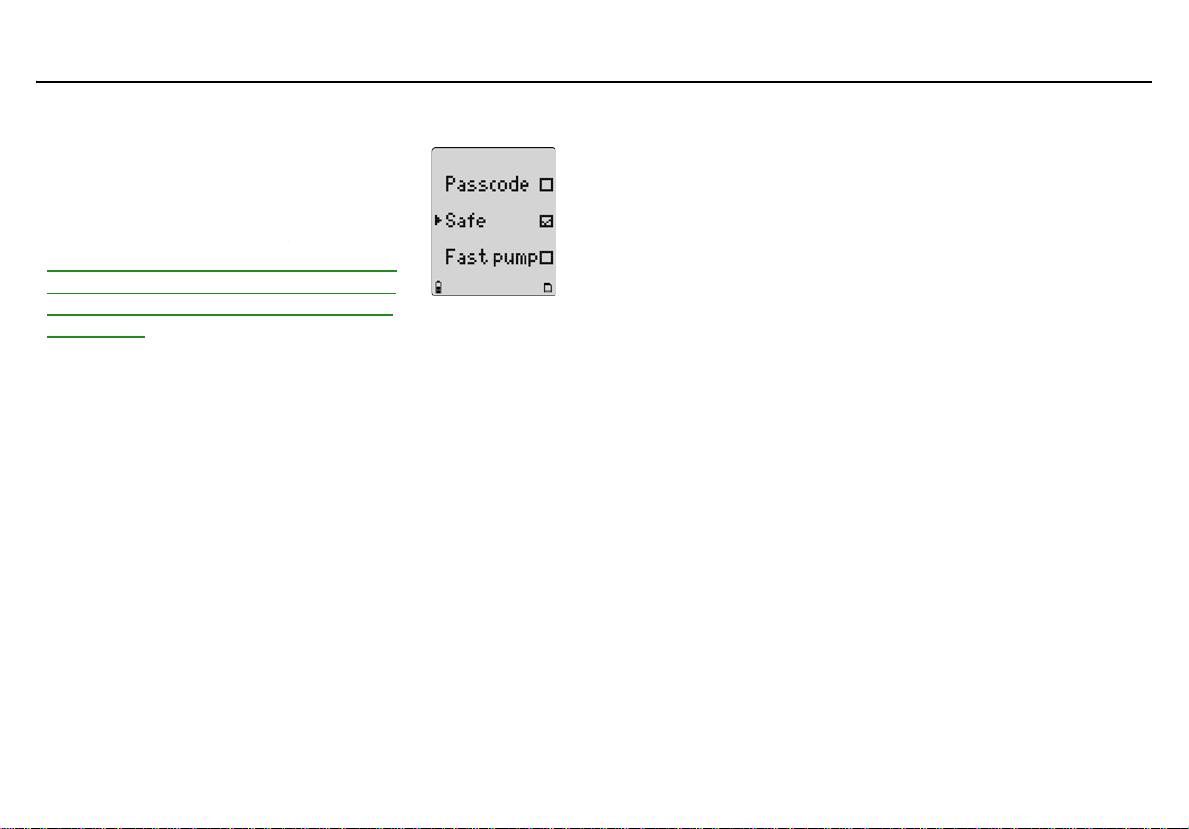
Safe Display Sensor Configuration
When enabled, the Safe option confirms that
conditions are normal and there are no gas
hazards present. When all gas levels are
normal or below the alarm setpoints, Safe
displays continually on the LCD.
Safe does not display if any active sensor has
failed, if any active sensor has an overdue calibration, and/or if any active sensor has failed
a bump test.
The detector is shipped with the Safe option
disabled.
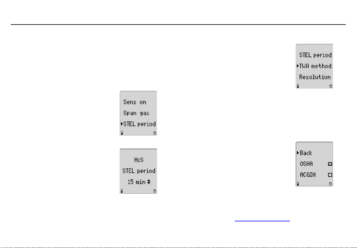
The Sensor option provides access to additional options and functions
for each sensor.
Depending upon the sensor that is selected, some or all of the following
options are available for configuration:
• Enabling/disabling a sensor
• Setting the span gas value
• Adjusting the STEL period (not applicable to LEL and O
• Selecting the TWA method (not applicable to LEL and O
• Resolution setting (not applicable to CO, LEL, O
sensors)
•% vol CO
•% vol CH
(CO2 sensor only)
2
(LEL sensor only)
4
• Selecting the correction factor (LEL and PID sensors only)
• Automatic calibration (O
sensor only)
2
GasAlertMicro 5/PID/IR
User Options Menu
sensors)
2
sensors)
2
, and CO2
2
25
Page 38

GasAlertMicro 5/PID/IR
User Manual
1. From the option menu screen, scroll to Sensors and press
C to access the following screen.
2. Press G or H to scroll to the desired sensor. Press C to con-
firm and to access the menu options specific to the selected
sensor.
For all sensor options, if a value is changed but not
confirmed within 5 seconds, the detector emits an
audible alarm and displays the following error message.
The detector retains the previous setting and returns to the
user options menu.
Sensor Enable/Disable
a Warning
Disabling a sensor should only be performed with
extreme caution. The disabled sensor cannot measure
and alarm against the applicable gas.
If a sensor fails, disabling the sensor deactivates the fail alarm. The
sensor should be replaced and enabled as soon as possible. The
detector will function normally with the remaining enabled sensors.
Note
Detectors that are configured for a 1, 2, 3, or 4 gases may contain a dummy sensor in one of the four sensor locations.
After selecting the desired sensor, the following screen displays.
Press C to toggle between enable/disable (sensor can be enabled at
any time).
Enabled
Disabled
26
Page 39

GasAlertMicro 5/PID/IR
User Options Menu
If disabled, the readings and the gas type for the sensor do not display
when in normal operation.
If a sensor is enabled but it is not installed in the detector, FAI L flashes
above the gas type of the missing sensor.
Disabled Enabled/not installed
If all the sensors are disabled, the following screens display.
Enable one or more sensors to exit and access normal operation.
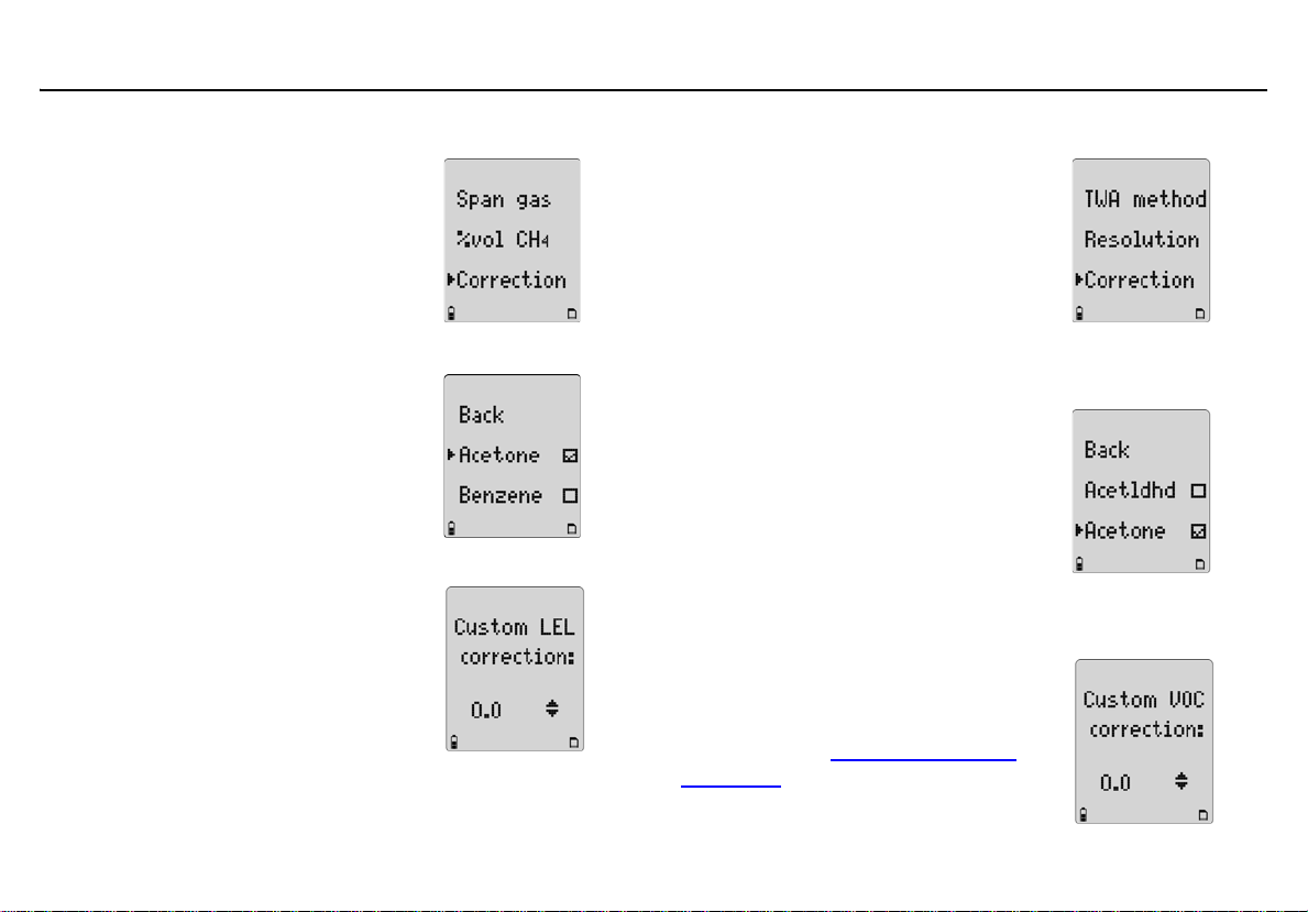
Span Gas Value
The Span gas option increases or
decreases the gas concentration for
calibration (must match the gas
concentration listed on the gas cylinder).
After selecting the sensor, press H to
scroll to Span gas and press C within
20 seconds to confirm.
Depending upon the sensor selected, a
screen similar to A or B displays. Press
G or H to scroll to the desired value and
press C within 5 seconds to confirm.
If C is not pressed within 5 seconds to
confirm the new value, the detector
retains the previous value and returns to
the user options menu.
Note
BW recommends that span concentration
values be set between specific ranges.
Refer to the Resetting Gas Alarm
Setpoints.
A
B
27
Page 40
GasAlertMicro 5/PID/IR
User Manual
STEL Period TWA Method
The short-term exposure limit (STEL period) option provides
protection for workers from over exposure to high concentrations
of gas, and is based on 5-15 minute intervals.
The STEL period option is available for
every toxic sensor.
After selecting the desired sensor, press
H to scroll to STEL period and press C
within 20 seconds to confirm.
The STEL period can be set from 5 to
15 minutes. Press G or H to scroll to the
required value, and then press C within
5 seconds to confirm.
If C is not pressed within 5 seconds to
confirm the new value, the detector
retains the previous value and returns to
the user options menu.
The detector is shipped with the STEL
period set to 15 minutes.
The TWA method (time-weighted average)
option is a safety measure used to calculate
accumulated averages of gases to notify the
user when the maximum average is
accumulated. The options are the OSHA or
ACGIH calculating method.
OSHA Method: 8 hour moving average—oldest value (first hour) is
replaced by the newest value (ninth hour).
ACGIH Method: Infinite accumulated average to 8 hours—total
accumulation, whether it is 2 hours or 8 hours.
After selecting the desired sensor, press H to scroll to TWA method.
Press C within 20 seconds to confirm.
A check displays in the checkbox of the
currently selected method. To select the
other method, press H to move the check
to the other method. Press C to confirm the
selection.
The detector is shipped with the OSHA
method enabled.
Note
If the TWA method has been changed, the TWA, STEL, and
MAX values must be reset to ensure the TWA is calculated
correctly. Refer to Clearing Gas Exposures
.
28
Page 41

GasAlertMicro 5/PID/IR
User Options Menu
Resolution
The Resolution option displays the gas
measurement using Regular or Extra
resolution.
Regular: Displays gas measurement in
1 ppm increments.
Extra: Displays the gas measurement in
0.1 ppm increments.
Note
Regular resolution for O
extra resolution is 0.01 ppm.
The Resolution option is not available for CO, O
and CO
sensors.
2
After selecting the desired sensor, press H to scroll to Resolution.
Press C within 20 seconds to confirm.
A check displays in the checkbox of the
currently selected resolution. To select the
other resolution, press H to move the
check to other resolution. Press C to
confirm the selection.
The detector is shipped with Regular
resolution enabled for applicable sensors.
and ClO2 sensors is 0.1 ppm, while
3
, LEL, PID,
2
%Vol CO2 (CO2 Sensors Only)
If the %vol CO2 is enabled, the detector
displays the carbon dioxide (CO
readings as %vol (0.0).
From the Sensors option menu, select
.
CO
2
Press H to scroll to %vol CO
to toggle between enable and disable.
Confirmation is not required. If no buttons
are pushed, after 20 seconds the detector
returns to the sensor selection screen.
The change is saved automatically.
The detector is shipped with %vol CO
disabled.
Correction factors are not applicable to the CO
)
2
. Press C
2
Note
2
sensor.
2
29
Page 42

GasAlertMicro 5/PID/IR
User Manual
%Vol CH4 (LEL Sensors Only) Correction Factor (CF)
If %vol CH
is enabled, any currently
4
enabled correction factor is ignored and
the detector operates assuming a
methane (CH
) calibration.
4
From the Sensors menu, select LEL and
press C to confirm.
Next, press H to scroll to %vol CH
and
4
press C within 20 seconds to confirm.
Press C to toggle between enable and
disable.
Confirmation is not required. If no buttons
are pushed within 20 seconds, the
detector returns to the sensor selection
screen. The change is saved
automatically.
Note
If changing the measurement unit
from % LEL to % Vol. or from % Vol.
to % LEL, a calibration must be completed and the alarm setpoints
changed. For calibration information
and for alarm setpoint information
refer to
Calibration and Setting Alarm
Setpoints on page 48.
Depending upon the selected sensor, refer to the following sections
LEL Sensor
or PID Sensor for more information.
Corrections factors are not applicable to CO
Note
sensors.
2
The detector is shipped with %vol CH
disabled.
30
4
Page 43
GasAlertMicro 5/PID/IR
User Options Menu
LEL Sensor
This option is used to enter compensation
factors for hydrocarbons other than
methane. The factor can only be applied if
the LEL sensor has been calibrated with
methane.
After selecting the LEL sensor, press H
to scroll to Correction. Press C within
20 seconds to confirm and access the LEL
correction library.
Scroll to the required gas type and
press C. A check displays in the
corresponding checkbox. The detector
automatically applies the correction factor.
To disable the Correction option, press H
to scroll to None or to Methane. A check
displays in the corresponding checkbox. If
required, select a different gas type
correction factor.
Custom: To enter a correction factor that
is not listed in the library, press H to scroll
to Custom and press C within 5 seconds
to confirm.
The Custom LEL correction screen displays. Press G or H to select the
required value, and press C within 5 seconds to confirm.
PID Sensor
This option is used to enter compensation
factors for selected gas types. The factor
can only be applied if the PID sensor has
been calibrated with isobutylene.
After selecting the PID sensor, press H
to scroll to Correction. Press C within
20 seconds to confirm and access the
PID correction library.
Scroll to the required gas type and
press C. A check displays in the
corresponding checkbox. The detector
automatically applies the correction factor.
To disable the Correction option,
press H to scroll to None or to Isobutyl.
A check displays. If required, select a
different gas type correction factor.
Custom: To enter a correction factor for
a custom PID sensor, scroll to Custom
and press C. Press G or H to scroll to
the required value, and press C within
5 seconds to confirm. Refer to the PID
Correction Factor PID Correction Factor
(CF) Library Library for gas types and
corresponding correction factor values.
31
Page 44

GasAlertMicro 5/PID/IR
User Manual
Note
The PID sensor is not sensitive enough to detect VOCs Benzene, Butadiene, and Vynil Chloride before they exceed their
toxic threshold limit value. The MicroDock II is still able to set
the Micro 5PID/IR to one of these VOCs. In this case the
Micro5/PID/IR will warn that the selection is not supported and
ask if you wish to continue. If the warning is not acknowl ed ged
the Micro 5/PID/IR will fail the PID Sensor until you reboot and
accept, or choose a different VOC.
Automatic Oxygen (O2) Calibration
When the Autocal option is
enabled, it forces the detector to
automatically calibrate the
oxygen sensor during startup.
If the Autocal option is enabled,
ensure the detector is activated
in a safe area that is free of
hazardous gas in an atmosphere
of 20.9% oxygen.
From the Sensor menu, press H
to scroll to O
within 20 seconds to confirm.
Press H to scroll to Autocal.
Press C
to toggle between enable/
disable.
The detector is shipped with the
Autocal option enabled.
and press C
2
32
Page 45

GasAlertMicro 5/PID/IR
User Options Menu
Logger Option
The Logger option is used to define how often the detector records a
datalog sample (once every 1 to 127 seconds).
From the user options menu, press H to scroll to Logger. Press C
within 20 seconds to confirm.
Press G or H to change the current logger rate. When the desired
value displays, press C within 5 seconds to confirm the new value.
If C is not pressed within 5 seconds, the following screen displays.
The detector is shipped with the datalog sample time set to 5 seconds.
Clock Option
The Clock option is used to change the date and time.
From the user options menu, press H to scroll to Clock. Press C
within 20 seconds to confirm.
33
Page 46

GasAlertMicro 5/PID/IR
User Manual
The screen displays showing the month highlighted indicating it is
selected to set.
Press G or H to scroll to the desired month and press C within
20 seconds to confirm. To bypass and retain the current setting, press
C. Continue setting/bypassing the remaining options.
The date/time options are set in the following order:
•month
•day
•year
•hour
• minutes
When the settings have been set or bypassed, the detector beeps twice
and returns to the user options menu.
Note
The detector is shipped with the date and time set to Mountain
Standard Time (MST).
Language Selection
The detector is shipped with English selected as the default language.
The available languages are as follows:
• Français (French)
• Deutsch (German)
• Español (Spanish)
• Prtuguês (Portuguese)
Press H to scroll to Language and press C within 20 seconds to
confirm.
Press G or H to scroll to the desired language and press C. A check
displays in the checkbox of the selected language.
34
Page 47

GasAlertMicro 5/PID/IR
User Options Menu
Wait for 20 seconds until the detector returns to the user options menu,
or press G to scroll to Back (English), Retour (French), Zurück
(German), Regreso (Spanish), or Retornar (Portuguese).
All screens now display in the selected language.
Tech Mode
a Warning
Tech mode should only be accessed by authorized
personnel.
Tec h mod e can only be accessed from the Language option. Press H
to scroll to Language. Do not press C until instructed.
In the following order, press and continue to hold each button until
Tech mode displays below the Language option.
1. Press and hold H with the right index finger.
2. Press and hold G with the right middle finger.
3. Press and hold C with the left thumb.
4. Press C to enter Tech mode. The options are as
follows:
• Sensors
• Initialize
• Force Calibration (Force calibration)
• Bump Daily
• Stealth Mode
• Sleep Mode
(Bump test daily)
35
Page 48

GasAlertMicro 5/PID/IR
User Manual
Sensors
a Caution
To reconfigure the sensor type, physically change the
sensor prior to entering Tech mode.
When a toxic sensor is physically removed and replaced by another toxic
sensor, the detector must be reconfigured to recognize the change.
Note
If a sensor is replaced, the detector will classify the sensor as
overdue for calibration. Calibrate the new sensor immediately.
1. Press H to scroll to Sensors. Press
C within 20 seconds to confirm and
access the toxic sensor menu.
2. Press G or H to scroll to Toxic 1
or Toxic 2 and press C within
20 seconds to confirm.
A corresponding list of toxic sensors
displays. A checkbox displays beside
the current toxic sensor.
Note
Toxic 1: List includes the PID and CO
sensors.
Toxic 2: List includes the H
sensor.
3. Press G or H to scroll to the new sensor and press C to confirm. A checkbox displays beside the new sensor. To reconfigure, exit the user options menu.
The following screen displays. The
detector deactivates and immediately
reactivates. It performs the
reconfiguration during the startup.
The new sensor must be calibrated.
Until the new sensor is calibrated, the
due date displays as OL (over limit)
when in normal operation.
4. Calibrate the new sensor immediately.
S/CO COSH
2
2
36
Page 49
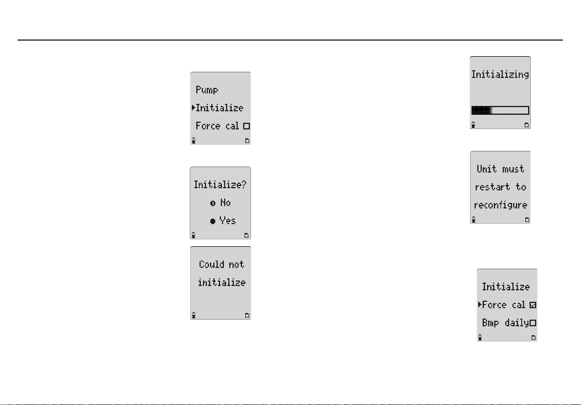
GasAlertMicro 5/PID/IR
User Options Menu
Initialize
The Initialize option restores the original factory default settings of the detector.
1. Press H to scroll to Initialize and press C within 20 seconds to confirm.
2. From the Initialize? screen perform one of the following options within 5 seconds.
• Press A No to exit, or
• Press C Yes to initialize.
If No is selected, the following screen
displays and the detector exits the initialize option.
If Yes is selected, the following screen
displays while performing the initializing
process.
When initializing is complete, the
following screen displays.
The detector deactivates and then
immediately reactivates. The detector
then reconfigures to the default settings
while it performs the self-test.
Verify all settings and alarm setpoints,
and then calibrate the sensors.
Force Calibration
If enabled, the Force cal option
automatically forces the detector to enter
calibration if a sensor is overdue upon
startup. Press H to scroll to Force cal.
Press C to toggle between enable and
disable.
The detector is shipped with the Force cal option disabled.
37
Page 50

GasAlertMicro 5/PID/IR
User Manual
Bump Daily
If enabled, the Bmp daily option forces the
detector to perform a daily bump test to
ensure that it is responding to the test gas.
Press H to scroll to Bmp daily. Press C
to toggle between enable/disable.
When enabled, the following screen
displays during the startup self-test.
The bump test must be performed for the
LEL and O
detector will deactivate. Refer to Bump
Daily Enabled for procedures.
The detector is shipped with the Bmp
daily option disabled.
If Bmp daily is enabled, the O
bump tests whenever the detector is activated (or reactivated)
following 00:00 hours (midnight).
sensors, otherwise the
2
Note
and LEL sensors require daily
2
Stealth Mode
The Stealth option disables the backlight,
visual alarms, and audible alarms when
concealment is required.
Only the vibrator and the LCD activate
during an alarm condition.
Press H to scroll to Stealth. Press C to
toggle between enable and disable.
The detector is shipped with the Stealth option disabled.
38
Page 51

Sleep Mode
Note
BW recommends the Sleep option be enabled when using
rechargeable battery packs.
If Sleep is enabled, sensor circuits remain
active after the detector is deactivated and
inserted into the charging cradle.
Press H to scroll to Sleep. Press C to
toggle between enable/disable.
Note
Enabling the Sleep option may
require the battery be charged more
frequently.
The detector is shipped with the Sleep
option disabled.
GasAlertMicro 5/PID/IR
User Options Menu
39
Page 52

GasAlertMicro 5/PID/IR
User Manual
Alarms
The following table describes the detector alarms and corresponding
screens.
• During an alarm condition, the detector activates the backlight and
displays the current ambient gas reading.
Alarms Screen` Alarms Screen
Low Alarm
• Fast beep
•Slow flash
•
L and gas type flash
• Vibrator alarm activates
High Alarm
• Constant beep
• Fast flash
•
L and gas type flash
• Vibrator alarm activates
• If more than one type or level of alarm exists simultaneously, a
multi alarm results.
• To change the factory-set alarm setpoints, refer to Calibration and
Setting Alarm Setpoints.
Table 7. Alarms
TWA Alarm
• Fast beep
•Slow flash
• L and gas type flash
• Vibrator alarm activates
STEL Alarm
• Constant beep
• Fast flash
• L and gas type flash
• Vibrator alarm activates
40
Page 53
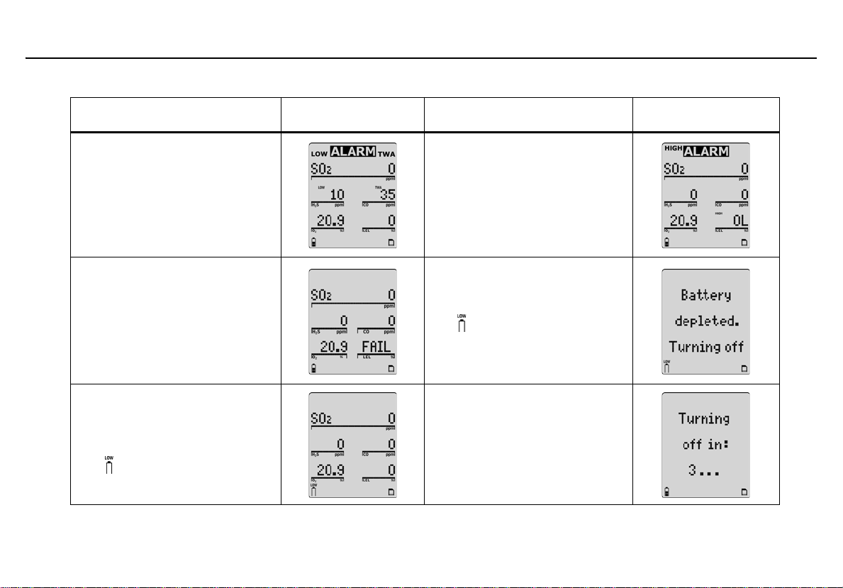
GasAlertMicro 5/PID/IR
Table 7. Alarms
Alarms Screen Alarms Screen
Alarms
Multi Alarm
• Alternating low and high alarm
beep and flash
•
L and gas types flash
• Vibrator alarm activates
Sensor Alarm
• One beep every 15 seconds
• FAIL flashes above the failed
sensor
Low Battery Alarm
• One beep and two flashes
every 25 seconds
• flashes
Over Limit (OL) Exposure
Alarm
• Fast beep and flash
•
L and gas type flash
• Vibrator alarm activates
Automatic Deactivation Alarm
• Eight beeps and flashes
• displays
• Vibrator alarm temporarily
activates
Normal Deactivation
• Three beeps and flashes
41
Page 54

GasAlertMicro 5/PID/IR
User Manual
Alarms Screen Alarms Screen
Table 7. Alarms
Confidence Beep
• One beep, one flash, and one
vibrate every 10 seconds
Alarms Screen
Pump Alarm
• Two fast beeps and alternating flashes
• Vibrator alarm activates
•
L and J flash
Note
If enabled, during an alarm condition the Latch (latching
alarms) option causes the low and high gas alarms (audible,
visual, and vibrator) to persist until the alarm is acknowledged
by pressing C and the gas concentration is below the low
alarm setpoint. The peak concentrations display continually
until the alarm condition no longer exists. Local regulations
may require the Latch Alarms option be enabled.
MMC/SD Fail Alarm
• One beep every 5 seconds
• S flashes
If the Stealth option is enabled, the detector only vibrates
during an alarm; the audible and visual alarms are disabled .
a Caution: If the detector emits a low battery alarm,
charge the lithium battery pack immediately.
42
Page 55

GasAlertMicro 5/PID/IR
Alarms
Gas Exposures Computed
a Warning
To avoid possible personal injury, do not deactivate
the detector during a work shift. TWA and STEL readings
reset if the detector is deactivated for more than
5 minutes.
Table 8. Computed Gas Exposures
Gas Exposure Description
Time-weighted average
(TWA) based on accumulated
TWA (toxic only)
STEL (toxic only)
*Peak (MAX)
exposure to toxic gases averaged over a work day according to OSHA or ACGIH
method.
Short-term exposure limit
(STEL) to gas based on a
5-15 minute user selectable
period.
Peak (MAX) concentration
exposure during work shift.
*For oxygen, it is the highest or the lowest concentration
encountered.
Viewing Gas Exposures
Press and hold C until the
peak (MAX) gas exposures
displays.
The TWA gas exposures
display next.
The STEL gas exposures
display last.
43
Page 56

GasAlertMicro 5/PID/IR
User Manual
Clearing Gas Exposures
The exposures automatically clear after 5 minutes when the detector
is deactivated.
To clear the MAX, TWA, and STEL exposure readings immediately,
press and hold C and G simultaneously. The detector displays the
following screen during the countdown.
Note
Hold C and G for the entire countdown, otherwise the MAX,
TWA, and STEL exposure readings will not clear.
Gas Alarm Setpoints
The gas alarm setpoints trigger the gas alarms and are described in
Table 9.
.
Table 9. Gas Alarm Setpoints
Alarm Condition
Low alarm Toxics and combustibles: Ambient
gas level above low alarm setpoint.
Oxygen: Ambient gas level may be
set above or below 20.9%.
High alarm Toxics and combustibles: Ambient
gas level above high alarm setpoint.
Oxygen: Ambient gas level may be
set above or below 20.9%.
TWA alarm Toxic only: Accumulated value above
the TWA alarm setpoint.
STEL alarm Toxic only: Accumulated value above
the STEL alarm setpoint.
Downscale alarm Toxic: If sensor reading is negative
(half of the TWA setpoint).
LEL: If sensor reading is negative
(half of the low alarm setpoint).
Multi alarm Two or more gas alarm conditions.
Viewing the Alarm Setpoints
To view the current alarm setpoints for all of the sensors, press G
during normal operation.
44
Page 57

GasAlertMicro 5/PID/IR
Alarms
The time/date, TWA, STEL, low, and high alarm setpoint screens display
in the following order left to right:.
If a correction factor has been applied to a sensor, one of the following
screens display indicating the sensor and gas type.
Resetting Gas Alarm Setpoints
Note
Standard factory alarm setpoints may vary by region.
The following table lists the factory alarm setpoints according to the
Occupational Safety and Health Association (OSHA) settings.
Table 10. OSHA Sample Factory Alarm Setpoints
Gas TWA STEL Low High
O
2
LEL N/A N/A 10% LEL 20% LEL
CO 35 ppm 50 ppm 35 ppm 200 ppm
H
2
PH
SO
Cl
2
NH
NO
HCN 4.7 ppm 10.0 ppm 4.7 ppm 10.0 ppm
ClO
O
3
VOC 50 ppm 100 ppm 50 ppm 100 ppm
CO
N/A N/A 19.5% vol. 23.5% vol.
S
10 ppm 15 ppm 10 ppm 15 ppm
0.3 ppm 1.0 ppm 0.3 ppm 1.0 ppm
3
2 ppm 5 ppm 2 ppm 5 ppm
2
0.5 ppm 1.0 ppm 0.5 ppm 1.0 ppm
25 ppm 35 ppm 25 ppm 50 ppm
3
2.0 ppm 5.0 ppm 2.0 ppm 5.0 ppm
2
0.1 ppm 0.3 ppm 0.1 ppm 0.3 ppm
2
0.1 ppm 0.1 ppm 0.1 ppm 0.1 ppm
5,000
2
ppm
30,000
ppm
5,000
ppm
30,000
ppm
45
Page 58

GasAlertMicro 5/PID/IR
User Manual
To change the factory-set alarm setpoints, refer to Calibration and Set-
ting Alarm Setpoints.
Note
To disable an alarm, set the alarm setpoint to 0 (zero).
Stopping a Gas Alarm
The low and high alarms stop when the ambient gas level returns to
below the low alarm setpoint.
Note
If alarms are set to latch, press C to acknowledge the alarm.
The alarms will persist until the alarm is acknowledged an d the
gas concentration is below the low alarm setpoint.
a Caution
Follow all safety procedures as defined by your
employer. Confirm with your supervisor before clearing
TWA and STEL alarms.
The TWA and STEL alarms can be stopped either by
• clearing the MAX, TWA, and STEL exposures (refer to Clearing
Gas Exposures), or
• deactivating the detector for 5 minutes (minimum) and then
reactivating it again.
Sensor Alarm
The detector tests for missing or defective sensors during the activation
self-test. If a sensor fails the self-test, FAI L flashes on the LCD above
the failed sensor. Refer to Troubleshooting
.
Pump Alarm
The external pump draws air over the sensors continually. If the pump
stops operating or becomes blocked, the detector activates the pump
alarm. The following screens display.
46
The pump alarm continues until the blockage is cleared or it is
acknowledged by pressing C. If C is pressed, the detector automatically launches a pump test to reset the pump module.
Page 59

GasAlertMicro 5/PID/IR
Bump Test
Refer to Pump Test for more information. If the pump test is successful,
the detector returns to normal operation, otherwise the pump alarm continues. If the pump alarm persists, refer to the Pump Operation section in
Troubleshooting
.
Low Battery Alarm
The detector tests the batteries upon activation and continuously
thereafter. Battery power is continually displayed during normal
operation. If the battery voltage is low, the detector activates the
low battery alarm.
The low battery alarm continues until the batteries are replaced/charged,
or until the battery power is almost depleted. If the battery voltage
becomes too low, the detector deactivates.
Note
Typ ically, the low battery alarm continues for 30 minut es before
the detector automatically deactivates.
Automatic Deactivation Alarm
If the battery voltage is in immediate danger of falling below the minimum
operating voltage, the audible alarm beeps eight times and the visual
alarm flashes eight times. After 3 seconds, the LCD dims and the
detector deactivates.
To replace or charge the batteries, refer to the following sections:
• Replacing the Alkaline Batteries
• Replacing the Lithium Battery Pack
Bump Test
A bump test is the process of applying a small amount of test gas to
force the detector into alarm. A bump test should be performed regularly
to confirm the sensors are responding correctly to gas, and that the audible, visual, and vibrator alarms activate during an alarm condition. Calibrate if the readings are not within specified limits.
Performing a Bump Test
a Caution
BW recommends to bump test the sensors before each
day’s use to confirm their ability to respond to gas by
exposing the sensors to a gas concentration that
exceeds the alarm setpoints.
To perform a manual bump test refer to
page 50 and the following steps 1-6. Follow this procedure when Bump
Daily is enabled.
The Calibration icon will flash if a sensor has failed a bump
test.
If performing a bump test on a pump unit, connect the calibration hose directly to the pump module.
Applying Gas to the Sensors on
Note
Note
47
Page 60

GasAlertMicro 5/PID/IR
User Manual
1. Connect the calibration hose to the 0.5l/min regulator on the
gas cylinder.
Note
Only use the calibration cap for bump tests and calibrations.
2. Connect the calibration hose to the intake inlet on the calibra-
tion cap. Arrows on the calibration cap indicate the direction of
gas flow.
3. Attach the calibration cap and tighten the knob.
Refer to
Applying Gas to the Sensors on page 50.
Note
Ensure the knob is securely fastened before applying gas. Do
not overtighten the calibration cap. Ensure strong air currents
are kept away from the exhaust side of the calibration cap, as
this can affect the bump test accuracy.
4. Apply gas. Verify the visual, audible, and vibrator alarms acti-
vate.
5. Close the regulator and remove the calibration cap from the
detector. The detector will temporarily remain in alarm until the
gas clears from the sensors.
6. Disconnect the calibration hose from the cap and regulator.
Calibration and Setting Alarm Setpoints
Guidelines
When calibrating the detector, adhere to the following guidelines:
Recommended gas mixture:
CO: 50 to 500 ppm balance N
S: 10 to 100 ppm balance N
H
2
PH3: 1 to 5 ppm balance N
SO2: 10 to 50 ppm balance N
Cl2: 3 to 25 ppm balance N
NH3: 20 to 100 ppm balance N
NO2: 5 to 50 ppm balance N
HCN: 5 to 20 ppm balance N
ClO2: 0.1 to 1.0 ppm balance N
O3: 0.1 to 1.0 ppm balance N
VOC:100 ppm isobutylene
LEL: 50% LEL or 2.5% by vol. methane balance air
: 5000 ppm balance air
CO
2
: 18.0%
O
2
• To ensure accurate calibration, use a premium-grade calibration
gas. Gases approved by the National Institute of Standards and
Technology (NIST) improves the validity of the calibration.
• Do not use a gas cylinder beyond its expiration date.
2
2
2
2
2
2
2
2
2
2
48
Page 61

GasAlertMicro 5/PID/IR
Calibration and Setting Alarm Setpoints
• Calibrate a new sensor before use. Install the sensor, activate
the detector, and allow the sensor to stabilize before starting
calibration.
Used sensor: 60 seconds / New sensor: 5 minutes
• Calibrate the detector at least once every 180 days (every 90 days
for HCN sensors) depending upon use and sensor exposure to
poisons and contaminants. For a list of common products that can
damage sensors, refer to Sensor Poisons and Contaminants
• Calibrate the detector if the ambient gas varies during startup.
• Calibrate the sensor before changing the alarm setpoints.
• Calibrate only in a safe area that is free of hazardous gas in an
atmosphere of 20.9% oxygen.
• To disable an alarm, set the alarm setpoint to 0 (zero).
• If the Auto cal option is enabled, the oxygen (O
automatically every time the detector is activated. Activate the
detector in a safe area that is free of hazardous gas in an
atmosphere of 20.9% oxygen.
• After activating the detector, allow it to stabilize for 1 minute before
performing a calibration or bump test.
• If a certified calibration is required, contact BW Technologies by
Honeywell.
Note
A generator must be used for O
and ClO2 sensors.
3
) sensor calibrates
2
.
Diagnostics Testing
The detector tests the ambient air (auto zero) and the test gas that is
applied (auto span) to ensure it meets expected values. Auto zero sets
the zero-gas level of the sensor. If ambient gas is present, the zero
level will be incorrect.
If excessive target gas is present, the detector displays an error
message and lists the affected sensor.
In auto span, if the target gas is not detected or does not meet expected
values, a message displays that the detector is exiting calibration mode.
The detector retains the previous set values.
49
Page 62

GasAlertMicro 5/PID/IR
User Manual
Applying Gas to the Sensors
The calibration cap, single gas calibration cap, and hose are shipped
with the detector. Refer to Figure 3.
The calibration cap and single gas calibration cap must only be
used during the calibration span process.
Figure 3. Applying Gas to the Sensors
and Table 11. for installation.
Note
Table 11. Applying Gas to the Sensors
Item Description
1
2
3
4
5
Detector with calibration cap
Calibration hose
Regulator and gas cylinder
Toxic 2 sensor position
Single gas calibration cap
Single Gas Calibration Cap
a Caution
If an O3 or ClO2 sensor is located in the Toxic 2 position
(refer to Figure 3.
cap must be used to ensure accurate calibration.
To calibrate O
refer to Figure 4.
1. Insert the cap into the Toxic 2 sensor position on the detector
2. Connect the calibration hose to the gas cylinder and to the
3. Proceed to Calibration Procedure
and ClO2 sensors using the single gas calibration cap,
3
(refer to Figure 3.
intake inlet on the cap.
and Tabl e 11.), a single gas calibration
, Table 12., and complete the following procedures.
). Press firmly until the release tabs click.
.
50
Page 63

GasAlertMicro 5/PID/IR
Calibration and Setting Alarm Setpoints
Table 12. Single Gas Calibration Cap
Item Description
1
2
3
4
Intake inlet
Calibration hose
Gas flow direction arrow
Output outlet
Figure 4. Single Gas Calibration Cap
Note
The arrow on the cap indicates the direction of gas flow from
intake to outtake.
Removing the Single Gas Calibration Cap
Using the thumb, push forward against both the inlet and the outlet
simultaneously to remove the cap from the detector.
Figure 5. Removing the Single Gas Calibration Cap
Calibration Procedure
To calibrate the detector and set the alarm setpoints, perform the
following procedure.
Note
To bypass a step during the calibration process (after auto
zero), press A.
51
Page 64

GasAlertMicro 5/PID/IR
User Manual
Start Calibration
Note
Verify that the calibration gas being used matches the span
concentration value(s) that are set for the detector. Refer to
Span Gas Value
bration. Correction factors that were set prior to calibration are
restored when the detector returns to normal operation.
The calibration icon will flash if a sensor has an overdue calibration
Calibrate only in a safe area that is free of hazardous gas
in an atmosphere of 20.9% oxygen.
1. To enter calibration, press and hold C and H simultane-
ously as the detector beeps, flashes, and vibrates to the
corresponding countdown.
. Correction factors are not applied during cali-
Note
a Caution
Depending upon the detector being calibrated, the auto zero
screens display differently.
GasAlertMicro 5/PID GasAlertMicro 5 IR
Note
Do not apply calibration gas during this process, otherwise the
auto zero step will fail.
Zero CO2 (GasAlertMicro 5 IR only)
If calibrating using the GasAlertMicro 5 or the GasAlertMicro PID, proceed to Auto Span
ceed to Passcode Protect
3. For GasAlertMicro 5 IR models, there is a second auto zero
that is performed for the CO
When auto zero for the other sensors is complete, the following
screen displays.
step #5. If the detector is passcode protected, pro-
step #4.
sensor.
2
Auto Zero and Oxygen (O2) Sensor Calibration
2. flashes while the detector automatically zeroes the
toxic and combustible sensors, and calibrates the O
52
sensor.
2
Page 65

GasAlertMicro 5/PID/IR
Calibration and Setting Alarm Setpoints
Press C Yes to zero the CO2 sensor.
Or
Press A No to bypass the CO
step #5. If the detector is passcode protected, refer to Pass-
code Protect Activated step #4.
If C Yes is pressed, the following screen displays.
zero and proceed to Auto Span
2
a Warning
Use nitrogen (N2) to zero the CO2 sensor.
Apply N
displays.
to zero the CO2 sensor. The following screen
2
flashes whiles the detector zeros the CO
sensor (approximately 30 seconds).
2
Passcode Protect Activated
4. When auto zero is complete and if the passcode protect option is enabled, the following screen displays.
The passcode must be entered to proceed.
Press G or H to scroll to the correct passcode and then press
C within 5 seconds to confirm. If entered correctly, the detector beeps twice and proceeds to Auto Span
Incorrect Passcode: If the passcode is incorrect or is not confirmed
within 5 seconds by pressing C, the following screens display.
step #5.
53
Page 66

GasAlertMicro 5/PID/IR
User Manual
The detector saves the calibration and returns to normal operation.
Auto Span
5. When auto zero is complete, the following screens display.
GasAlertMicro 5 and PID
GasAlertMicro 5 IR
.Note
Span sensors in the following order:
• Exotics (NH
, ClO2, O3, Cl2, and CO2)
3
• Single gas
• Quad gas (H
S, CO, LEL, and O2)
2
•PID
Note
A generator must be used for O
and ClO2 sensors.
3
To ensure accurate calibration, a single gas calibration cap
must be used to calibrate O
: Use a Tedlar bag as a buffer between the generator
• ClO
2
and ClO2 sensors.
3
and the detector (using the single gas calibration cap) to
regulate the flow rate to ensure accurate readings.
Allow the Tedlar bag to fill for several minutes before
initiating calibration.
: Calibrate using the generator and the single gas
• O
3
calibration cap. Do not use a Tedlar bag.
Set the generator to 0.5 ppm at a flow rate of 0.5 l/min.
Depending upon the gas cylinder being used, one or all four sensors
can be calibrated at one time.
Apply Span Gas Now
54
Page 67

GasAlertMicro 5/PID/IR
Calibration and Setting Alarm Setpoints
Attach the calibration cap (or single gas calibration cap for O3
and ClO
to Figure 3.
) and apply gas to the sensor(s). To attach caps, refer
2
.
Refer to the following flow rates:
• 1000 ml/min. for NH
• 500 ml/min. for CO
and Cl
3
2
2
• 250-500 ml/min. (all other sensors)
K flashes as the detector initially detects the calibration gas.
GasAlertMicro 5 and PID GasAlertMicro 5 IR
After 30 seconds the detector beeps and K stops flashing.
flashes while spanning the sensors until the detector
has attained a sufficient level of the expected gas.
Refer to Table 13.
for times required to span.
Table 13. Time Required to Span
Exotic toxic gases 5 minutes
LEL (combustibles) 30 seconds
PID gases 2 minutes
Insufficient Level: If a sensor does not attain a sufficient level
of expected gas, it is cleared from the LCD and is not spanned.
Gas Type Time Required to Span
Most toxic gases and CO
2
2 minutes
55
Page 68

GasAlertMicro 5/PID/IR
User Manual
While the detector is spanning the sensor(s), a countdown of
time remaining displays in the lower left of the screen.
GasAlertMicro 5 and PID GasAlertMicro 5 IR
When the span is complete, the following screen
displays.
Successful Span: Proceed to Successful Span
Unsuccessful Span: Refer to
ble solutions.
Unsuccessful Span for possi-
step #6.
Successful Span
6. If the sensor(s) has spanned successfully, the audible alarm beeps three times and the following screens display.
If there are more sensors to span, remove the current cylinder
and connect the next gas cylinder.
Press G and apply gas to span the other sensor(s).
Or
Press H to end the span and proceed to Setting the Calibra-
tion Due Date step #7.
When all sensors have spanned, the following screen displays.
56
If a sensor fails to span, refer to
calibration section for possible solutions.
Unsuccessful Span at the end of the
Page 69

GasAlertMicro 5/PID/IR
Calibration and Setting Alarm Setpoints
Setting the Calibration Due Date
7. When the span is complete, the calibration due date can be set for each sensor that has spanned successfully. The following screen displays.
Press C to set the calibration due dates.
Or
Press A to bypass and proceed to Alarm Setpoints
Note
If a new due date is not entered, the detector automatically
resets to the previously entered number of days.
step #8.
The calibration due dates are set in the following order:
•Toxic 1
•Toxic 2
•LEL
•O
2
If the due date of an unsuccessfully spanned sensor is
changed, the following screens display.
The detector then automatically proceeds to the next sensor.
To change the calibration due date (1-365 days), press H or
G until the new value displays. Press C within 5 seconds to
confirm.
Or
Press A to bypass a sensor and proceed to the next sensor.
57
Page 70

GasAlertMicro 5/PID/IR
User Manual
Note
If a value is changed but C is not pressed within 5 seconds to
confirm, the following screen displays.
The previous value is automatically retained. The detector
proceeds to the next sensor due date.
Repeat step #7 to set the calibration due dates for the remaining sensors.
When all of the due dates are entered, press C to proceed to
Alarm Setpoints
Or
Press A to bypass setting the alarm setpoints and proceed to
Finish Calibration
step #8.
step #10.
Alarm Setpoints
8. When all of the sensor due dates have been set or bypassed, the alarm setpoints need to be set or bypassed. The following screen displays.
Factory alarm setpoints may vary by region. Refer to Resetting
Gas Alarm Setpoints for an example.
Alarms can be set to any value within the detection range of
the selected sensor. Refer to Detection Range in Specifica-
tions.
Note
To disable an alarm setpoint, set it to 0 (zero).
58
Page 71

GasAlertMicro 5/PID/IR
Calibration and Setting Alarm Setpoints
If a new setpoint is entered but not confirmed within 5 seconds
by pressing C, the following screen displays.
The previous setpoint is retained and the detector
proceeds to the next setpoint.
The setpoints are set in the following order:
• TWA (if applicable)
• STEL (if applicable)
•low
•high
To bypass a setpoint, press C to save the current value and
proceed to the next setpoint.
Setting the TWA Alarm Setpoint
The current TWA alarm setpoint displays for the selected sensor
(if applicable).
Press H or G to change the value for the TWA alarm setpoint. When
the required value displays, press C to confirm.
Setting the STEL Alarm Setpoint
The current STEL alarm setpoint displays for the selected sensor
(if applicable).
Press H or G to change the value for the STEL alarm setpoint. When
the required value displays, press C to confirm.
59
Page 72

GasAlertMicro 5/PID/IR
User Manual
Setting the Low Alarm Setpoint
The current low alarm setpoint displays for the selected sensor.
Press H or G to change the value for the low alarm setpoint. When the
required value displays, press C to confirm.
Setting the High Alarm Setpoint
The current high alarm setpoint displays for the selected sensor.
Press H or G to change the value for the high alarm setpoint. When the
required value displays, press C to confirm.
Proceed to step #9 Setting the Remaining Alarm Setpoints
.
Setting the Remaining Alarm Setpoints
9. Repeat step #8 to set the alarm setpoints for the remaining
sensors. When complete, the detector emits two quick beeps
and proceeds to Finish Calibration
.
Finish Calibration
10. The detector displays the following screen to indicate that calibration is complete.
60
Page 73

GasAlertMicro 5/PID/IR
Calibration and Setting Alarm Setpoints
Verification
1. After calibration is complete and the detector returns to normal operation, verify the calibration by using a gas cylinder other than the one used for calibration.
2. The gas concentration should not exceed the sensor's detection range. Confirm that the LCD displays the expected concentration values.
3. To ensure the reading is accurate, apply the verification gas for the same amount of time as was applied to the sensor when it was calibrated.
Example: SO
verification gas for 2 minutes.
span time 2 minutes therefore, apply
2
Unsuccessful Span
If the sensor(s) did not span successfully, refer to the following sections
for possible solutions:
• Failed Span
• No Gas Detected
• Did Not Reach Target Span
• Large Span
Failed Span
If a sensor fails the span, the following error message displays.
If the sensor is not calibrated, it displays as FAIL in normal operation the
next time the detector is activated.
61
Page 74

GasAlertMicro 5/PID/IR
User Manual
If all sensors fail the span, the following screen displays.
1. Ensure the regulator valve is open and that the gas cylinder is not past the expiration date. Replace the gas cylinder and/ or regulator if required.
2. Replace the sensor(s) and sensor filter if required.
3. Press A to exit and then calibrate again in a safe area that is free of hazardous gas in an atmosphere of 20.9% oxygen.
4. If the span fails a second time, reactivate the detector to test the sensors.
If all sensors fail the span, the calibration due dates cannot be reset. The
following screens display.
No Gas Detected
If the detector does not detect any gas within 30 seconds, the following
screens display.
1. Ensure the regulator valve is open and the calibration hose is free of debris.
2. Replace the gas cylinder and/or regulator if required.
3. Replace the sensor(s) and sensor filter if required.
4. Press G to reapply gas or press H to end the span.
Did Not Reach Target Span
If the target span was not achieved, as defined in the Span Gas Value
option, the following screens display.
62
Page 75

Not reaching the target span can result from
• a problem with the span gas,
• the gas cylinder being past the expiry date, or
• a problem with the sensor.
Accept Current Span: If the gas cylinder, regulator, and sensor
are operating correctly, press C to accept the current span.
Reject Current Span: Press A to reject. Verify the gas cylinder,
detector settings, and sensor are operating correctly. Calibrate the
sensor again.
Large Span
If the span adjustment is unusually large (more than 15%), the following
screens display.
Ensure the correct gas cylinder being used and that the span concentration value(s) of the detector matches the span concentration value(s) of
the gas cylinder. Refer to Span Gas Value
Adjustment Expected: If the calibration adjustment is expected,
press C to accept the span.
Adjustment Not Expected: If the calibration adjustment is not
expected or the span gas value does not match the gas cylinder,
press A to reject the span and calibrate that sensor again.
.
GasAlertMicro 5/PID/IR
Calibration and Setting Alarm Setpoints
63
Page 76

GasAlertMicro 5/PID/IR
User Manual
Pump
When using the pump module, attach it and the pump accessories prior
to activating the detector.
The pump module can be used independently to measure gas or it can
be used with the sample probe to test for gases in confined spaces. To
measure gas using the sample probe, refer to Confined Space Sampling
a Warning
If the pump module is installed on the detector, the
following three things must occur during start-up. If any
one of the conditions below does not occur, discontinue
use of the detector and contact BW Technologies by
Honeywell immediately.
• The detector prompts for a pump test during start-up
• The pump module passes the pump test at start-up when
the pump inlet or sample chain inlet is blocked
•The J icon displays on the LCD
To ensure accurate gas detection, the sensors must be
calibrated immediately when the pump module is
replaced by the diffusion cap and vice versa.
When using the sample probe at -10°C to +0°C (14°F to
32°F), keep the sample probe in your hand.
a Caution
A demand flow regulator must be used to manually
calibrate the GasAlertMicro 5/PID/IR detector when the
pump module is installed.
The calibration cap is designed for use with the diffusion
cap only. It cannot be used with the pump module.
Identifying the Pump
.
There are two generations of pump. The best way to differentiate the
Generation 2 pump from the Generation 1 pump is the inline filter that is
visible on the Generation 2 pump on the left-hand side.
Each model of pump has different operating specifications. Refer to
Maximum Hose Length when Confined Space Sampling on page 71.
Generation 1: 116885-L3 (yellow) and 118933-L3 (black)
64
Page 77

Generation 2: 130916-L3 (yellow) and 130917-L3 (black)
GasAlertMicro 5/PID/IR
Pump
65
Page 78

GasAlertMicro 5/PID/IR
User Manual
Installing the Pump Module
Figure 6. Installing the Pump Module
Table 14. Installing the Pump Module
Item Description
1 Pump module
2 Sensor filter
3Detector
4 Machine screws (2)
To install the pump module, refer to Figure 6., Table 14., and the
following procedures.
1. Deactivate the detector.
2. Remove the two machine screws and the sensor cover. Remove the sensor filter from the sensor cover and insert it into the pump module.
3. Attach the pump module to the detector and replace the two machine screws.
4. If sampling in a confined space, attach the sample probe. Refer
to Confined Space Sampling
If using an auxiliary filter as an additional filtration system, refer
to Attaching the Auxiliary Filter
5. Activate the detector. The detector performs a pump test
during the startup self-tests. Refer to Pump Test
.
.
.
66
Page 79

GasAlertMicro 5/PID/IR
Installing the Pump Module
Replacing the Pump Filter (Generation 2 Pump)
To replace the Generation 2 pump filter, refer to Figure 7. and the following steps 1-8.
Note
If using the auxiliary filter on the Generation 1 pump or as an
additional filtration system on the new pump module, refer to
Attaching the Auxiliary Filter
Figure 7. Replacing the Pump Filter (Generation 2 Pump)
.
1. Deactivate the detector.
2. Remove the filter window screw.
3. Remove the filter window.
4. Remove the old filter from the filter window.
Important! Ensure the filter cavity and filter window are clean
and free of debris.
5. Insert a new filter.
6. Replace the filter window and screw.
7. Activate the detector. The detector performs a pump test
during the startup self-tests to verify the pump module is operating correctly.
8. To order additional filters, refer to Replacement Parts and
Accessories.
a Caution
Filters may need to be replaced more frequently in high
particulate areas. BW Technologies by Honeywell
recommends that the auxiliary filter be used as a
additional filtration in high particulate areas.
67
Page 80

GasAlertMicro 5/PID/IR
User Manual
Replacing the Pump Nozzle (Generation 2 Pump)
To replace the pump nozzle for the Generation 2 pump, refer to Figure 8.
and step 1-4.
Figure 8. Replacing the Pump Nozzle
Note
If the nozzle is damaged, replace it immediately to ensure
accurate pump flow . To order addit io nal pump no zzle s, refe r to
Replacement Parts and Accessories
1. Deactivate the detector.
2. Gently insert a medium-sized flathead screwdriver into the nozzle slot. Twist the screwdriver slightly to lift and remove the damaged nozzle.
68
.
3. Insert the new nozzle. Ensure the nozzle post inserts correctly into the nozzle gasket.
4. Activate the detector. The detector performs a pump test
during the startup self-tests to verify the pump module is operating correctly.
Attaching the Auxiliary Filter
The Pump Module Auxiliary Filter (“the filter”) is used to filter out
particulates that can decrease the life span of the pump.
Figure 9. Attaching the Auxiliary Filter
Page 81

GasAlertMicro 5/PID/IR
Installing the Pump Module
a Caution
The filter is designed to protect the pump. For
Generation 1 pumps, the filter must be connected when
the pump is activated. Only remove the filter to perform
calibrations, bump tests, and when using the sample
probe.
For new model pumps, the auxiliary filter can be used as
an additional filtration system in high particulate areas.
To insert the auxiliary filter, complete the following:
1. Loop the filter cord through the ring on the alligator clip and pull the filter through the loop of the filter cord.
Note
Attaching the filter cord to the alligator clip ensures the filter
remains with the detector when not in use.
2. Pull the filter cord tight. Ensure the loop knot is secure.
3. Align the pump quick connector with the filter quick connector and turn clockwise. Ensure the connection is secure.
4. Change the filter as required. Environments with heavy airborne particulates require the filter to be changed
frequently.
To order additional filters, refer to Replacement Parts and
Accessories.
Figure 10. Attaching the Filter Cord
69
Page 82

GasAlertMicro 5/PID/IR
User Manual
Confined Space Sampling
The sample probe is used to safely test for gas in confined spaces
before entering.
Attach the sample probe to the pump module prior to activating the
detector.
a Warning
To measure hazardous gas in a confined space, the
sample probe must be used with the pump module.
Figure 11. Attaching the Sample Probe
a Caution
To prevent the Teflon lining inside the Tygon tubing from
causing a blockage when connecting it to the sample
probe, the end of the tubing must be flared. Refer to
steps 3 and 4.
Note
The detector and pump module can also be used with a sintered filter.
1. Deactivate the detector.
2. Attach the pump connector end of the teflon-lined Tygon tubing to the nozzle on the pump module.
3. Gently insert needle nose pliers into the other end of the teflonlined Tygon tubing. Using a circular motion, flare the end of the
tubing.
4. Connect the flared end of the tubing to the sample probe.
Ensure the teflon lining does not separate from the Tygon tubing, as it will block the tube and generate a pump alarm.
5. Activate the detector. Ensure all connections are secure before sampling.
6. Insert the sample probe into the confined space.
70
a Warning
Depending upon the length of the tubing and the type of
gas in the confined space, allow a minimum of 3
Page 83

GasAlertMicro 5/PID/IR
Installing the Pump Module
seconds per foot of tubing to ensure the readings
stabilize before entering the area.
Example: 10 ft. = 30 seconds
Maximum Hose Length when Confined Space Sampling
Maximum sample hose length is dependent on pump model, operating
temperature, and sampling accessory. Refer to the tables below.
a Caution
Maximum sample hose length is dependent on an inner
1/16” hose diameter.
Table 15. Generation 1 Pump Maximum Hose Length
-10°C to +0°C
(14°F to 32°F)
Sintered filter 3 m (10 ft.) 9.1 m (30 ft.)
Sample Probe 3 m (10 ft.) 3 m (10 ft.)
a Warning
When using the sample probe at -10°C to +0°C (14°F to
32°F), keep the sample probe in your hand.
0°C to 50°C
(32°F to 122°F)
Table 16. Generation 2 Pump Maximum Hose Length
-20°C to 50°C
(-4°F to 122°F)
Sintered filter 20 m (66 ft.)
Sample Probe 3 m (10 ft.)
71
Page 84

GasAlertMicro 5/PID/IR
User Manual
Datalogger
Detectors equipped with the datalogger option record information that
can be compiled to create a report. To set how often the detector records
a sample (1-127 seconds), refer to Logger Option
menu.
The following information is recorded in a datalog:
• Date and time
• Serial number of the detector
• Type of gas the detector monitors
• Gas reading(s) that display
• STEL and TWA readings
• Sensor status
• Detector status
• Passcode protect enabled/disabled
• STEL period setting
• Confidence beep enabled/disabled
• Automatic backlight enabled/disabled
• Stealth mode is enabled/disabled
• Latching alarm enabled/disabled
• Calibration past due option enabled/disabled
• Language the detector is set to display
in the user options
MMC/SD Card Compatibility
For a list of compatible memory cards, please contact BW Technologies
by Honeywell.
Inserting the MMC/SD Card
To insert the MMC/SD card into the detector, refer to the following steps
1-5 and Figure 12.
1. Deactivate the detector.
2. Release the latch and remove the battery pack.
3. Insert the MMC/SD card (pins face down).
4. Replace the battery pack and secure the latch.
5. Activate the detector. The MMC/SD card is automatically formatted during the startup self-test.
.
72
Page 85

GasAlertMicro 5/PID/IR
MMC/SD Card Troubleshooting
Figure 12. Inserting/Removing the MMC/SD Card
MMC/SD Card Troubleshooting
The MMC/SD card is not required for operation in detectors equipped
with datalogging. However, the following two screens display if the card
is not inserted during startup.
A new MMC/SD card is automatically formatted when it is inserted in the
detector. When the detector is activated, it begins the self-test and then
displays the following screen.
73
Page 86
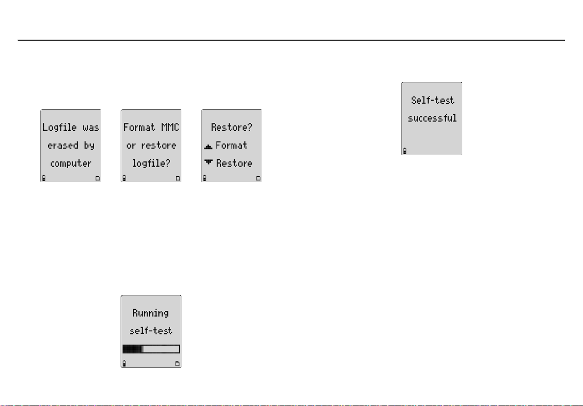
GasAlertMicro 5/PID/IR
User Manual
Restoring Datalog Files
If the MMC/SD card has been accidentally reformatted or erased by the
computer application, the following screens display when the card is
inserted into the detector.
a Caution
Only erased data files can be restored using the detector.
Computer applications sometimes write data over erased
files, and that erased data cannot be restored by the detector.
Always create back up files on the computer.
To restore the logfile, complete the following:
1. From the detector, press H to restore the logfile. The
following screen displays.
If the detector successfully restores the logfile, the
following screen displays and the startup tests continue.
2. From the computer, verify that the logfile has been restored. When the normal operation screen displays, deactivate the detector.
3. Remove the MMC/SD card and insert it into the card reader.
4. From the computer desktop, double-click My Computer to view the list of drives.
5. Double-click the Removable Disk drive to access LOG-
FILE0.csv. Open the logfile and verify that the data has been
restored.
If LOGFILE0.csv does not display, ensure that the MMC/SD
card is inserted in the card reader correctly and that all connections are secure.
6. After verifying that the logfile has been restored, re-insert the MMC/SD card into the detector.
74
Page 87

GasAlertMicro 5/PID/IR
MMC/SD Card Troubleshooting
Reformatting the MMC/SD Card
To reformat the MMC/SD card, complete the following:
1. Insert the MMC/SD card into the card reader.
2. From the computer desktop, double-click My Computer to
view the list of drives.
3. Double-click the Removable Disk drive to access LOG-
FILE0.csv.
4. Select LOGFILE0.csv and delete.
5. Insert the MMC/SD card into the detector.
6. Activate the detector. The startup self-test begins and the following screens display.
7. Press G to format the MMC/SD card. The following screen dis-
plays.
For any additional MMC/SD card errors, refer to
Troubleshooting
.
75
Page 88

GasAlertMicro 5/PID/IR
User Manual
Import Datalogs to Fleet Manager II
Note
Refer to the following minimum requirements before importing
datalogs to Fleet Manager II.
Minimum PC Requirements
• 500 MHz Pentium (or equivalent)
• 100 MB free hard disk space
• Windows XP or Vista
• USB port
Importing from MicroDock II to Fleet Manager II
If the detector is used with the MicroDock II Station to import datalogs to
Fleet Manager II, refer to the MicroDock II User Manual for complete
instructions.
Import to Fleet Manager II Using a Card Reader
To import a datalog file from the detector to Fleet Manager II, complete
the following:
1. Deactivate the detector.
2. Release the latch and remove the battery pack.
3. Remove the MMC/SD card from the detector. Refer to Figure
12. and 1.
4. Connect the card reader to the USB port on the computer.
5. Insert the MMC/SD card into the card reader (ensure the pins face down).
6. Open Fleet Manager II. Click Start > All Programs > BW
Technologies > Fleet Manager II > BW Technologies Fleet
Manager II.
7. From the top task bar, click Help > User Manual.
8. Refer to section “Importing Data into Fleet Manager II”.
76
Page 89

View Datalog Files in Spreadsheets
The datalog files can be downloaded from the MMC/SD card into most
spreadsheet applications using a card reader.
Compatible software applications are
• Microsoft® Excel 98 or higher,
• Quattro Pro,
• Lotus 1-2-3,
• Microsoft® Access, and
• Microsoft® Word.
To view a datalog file in a software spreadsheet, complete the following:
1. Deactivate the detector and remove the MMC/SD card (refer
to Figure 12.
2. Insert the MMC/SD card into the card reader.
3. From the computer desktop, double-click My Computer to view the list of drives.
4. Double-click Removable Disk drive.
5. Double-click LOGFILE0.csv.
6. Refer to Table 17.
The Unit Config column (far right) in Table 17.
codes. Refer to Table 18.
codes.
).
for an example of the datalog spreadsheet.
contains letter
and Table 19. for definitions of the
GasAlertMicro 5/PID/IR
View Datalog Files in Spreadsheets
77
Page 90

GasAlertMicro 5/PID/IR
User Manual
Example of a Datalog Spreadsheet
When datalog information is imported into most spreadsheet software, it
appears similar to the example below.
a Warning: Some compatible software packages have an internal
Not all columns are included in this example. Additional Toxic
TWA and Toxic STEL display on a normal spreadsheet.
Table 17. Datalog Spreadsheet Example
Note
file size limit and may not load the entire file. Check the software
limit.
Date
dd-mm-yy
23-12-05 #4 9:54:25 5 10 35 -- -- 33------ S104-000001
23-12-05 #4 9:54:30 10 15 50 -- -- 44------ S104-000001
23-12-05 #4 9:54:35 5 10 35 10 19.5 -- -- 1111---- S104-000001
23-12-05 #4 9:54:40 10 15 200 20 23.5 -- -- 2222---- S104-000001
23-12-05 #4 9:54:45 0 0 0 24 20.9 -- -- -D-E---D S104-000001 FCEKNL
23-12-05 #4 9:54:50 0 0 0 24 20.9 0 0 -------- S104-000001 FCEKNL
23-12-05 #4 9:54:55 0 0 0 24 20.9 0 0 --L----L S104-000001 FCEKNL
23-12-05 #4 9:55:00 0 0 0 24 20.9 0 0 LLH----M S104-000001 FCEKNL
23-12-05 #4 9:55:05 5 10 35 0 0 LLH----M S104-000001
23-12-05 #4 9:55:10 10 15 50 0 0 LLL----M S104-000001
23-12-05 #4 9:55:15 5 10 35 10 19.5 0 0 -L-----L S104-000001
23-12-05 #4 9:55:20 10 15 200 20 23.5 0 0 -------- S104-000001
23-12-05 #4 9:55:25 0 0 0 24 20.9 0 0 -------B- S104-000001 FCEKNL
23-12-05 #4 9:55:30 0 0 0 24 20.9 0 0 ------B- S104-000001 FCEKNL
Day
Mon=1
Time
hh:mm:ss
Toxic1
ppm
Toxic2
ppm
Toxic3
ppm
LEL
%CH4
%LEL
O2%Toxic 1
TWA ppm
Toxic 1
STEL ppm
Status
Codes
Serial
Number
Unit
Config
78
Page 91

Table 18. Datalog Status Codes
Normal operation
Low alarm
L
High alarm
H
TWA alarm
T
TWA and low alarm (dual alarms)
U
TWA and high alarm (dual alarms)
V
STEL alarm
s
STEL and low alarm (dual alarms)
u
Fresh air delay
f
Zero CO
@
Plugged (blocked) - pump alarm
P
Batteries OK
Low alarm
L
High alarm
H
TWA alarm
T
2
Status Codes
Backlight is on
G
STEL and high alarm (dual alarms)
v
TWA and STEL alarm (dual alarms)
w
TWA, STEL, and low (triple alarms)
x
TWA, STEL, and high (triple alarms)
y
Overload / sensor is over-ranged
O
Calibrating
C
Failure - sensor failure
F
Time set
I
Pump Codes
Failure / pump failure
F
Battery Status Codes
Low battery alarm
B
Alarm Status Codes
Multi alarm
M
Calibration
C
Off / quit / manual deactivation
Q
GasAlertMicro 5/PID/IR
View Datalog Files in Spreadsheets
Alarm setpoint 1 (low alarm)
1
Alarm setpoint 2 (high alarm)
2
Alarm setpoint 3 (TWA alarm)
3
Alarm setpoint 4 (STEL alarm)
4
Calibration due date (days)
D
Elapsed / last calibration (days)
E
Auto zeroing
Z
Testing
t
Confidence beep is active
C
Automatic shutdown
S
Failure / self-test fail
F
RTCC / real-time clock failure
R
Note: TWA readings greater than 99 are recorded as OL.
79
Page 92

GasAlertMicro 5/PID/IR
User Manual
Table 19. Datalog Gas and Correction Factor Sensor Codes
No sensor B H2S C H2S COSH D CO E CO COSH
A
SO
F
K
Q
A
F
K
P
U
A
F
K
P
U
V
2
NH
3
IR
Acetaldhyde B Acetone C Ammonia D Benzene E Butadiene
Diesel G Ethanol H Ethylene I Gasoline J Hexane
Isobtyln L JP8 M Kerosene N MEK O Naptha
Styrene Q Toluene R Turpentine S Vinyl_Cl T Xylene
Custom
Acetone B Benzene C Butane D Cyclohexane E Ethanol
Ethyl_Ace G Gasoline H Heptane I Hexane J Hydrogen
Isobutylene L Isopropanol M MEK N Methane O Methanol
Octane Q Pentane R Propane S Toluene T Turpentine
Custom
LEL in % by Vol CH
G PH
L ClO
4
3
2
Correction Factor Codes for PID (if applicable)
Correction Factor Codes for LEL
Gas Sensor Codes
H NO
M O
2
3
LEL Unit Codes
L LEL in % LEL
I HCN J Cl
O LEL P PID
2
80
Page 93

GasAlertMicro 5/PID/IR
Maintenance
Maintenance
To maintain the detector in good operating condition, perform the
following basic maintenance as required.
• Calibrate, bump test, and inspect the detector at regular intervals.
• Maintain an operations log of all maintenance, calibrations, bump
tests, and alarm events.
• Clean the exterior with a soft damp cloth. Do not use solvents,
soaps, or polishes. Refer to Sensor Poisons and Contaminants
• Do not immerse the detector in liquids.
Battery Cautions
a Warning
To avoid personal injury and/or property damage, adhere
to the following:
• Replace the batteries immediately when the detector emits
a low battery alarm.
• Use only batteries that are recommended by BW
Technologies by Honeywell. Refer to Specifications
• Ensure the alkaline batteries are properly installed in the
detector battery pack.
• Charge batteries using only a recommended BW charger.
Do not use any other charger. Failure to adhere to this
caution
can cause fire and/or explosion.
• Do not calibrate the detector during or immediately after
charging.
• Both the rechargeable lithium battery pack and the alkaline
battery pack are user-changeable in hazardous locations,
but the alkaline battery cells inside the pack can only be
replaced in a safe area that is free of hazardous gas.
• Warning: The battery pack (M5-BAT08) that is equipped with
a lithium polymer cell may present a risk of fire or chemical
.
.
burn hazard if misused. Do not recharge, disassemble, heat
above 212ºF (100ºC), or incinerate.
• Warning: Do not use any other lithium batteries with the
Micro5/PID/IR detectors. Use of any other cell can cause fire
and/or explosion. To order a replacement lithium battery
pack (M5-BAT08), refer to Replacement Parts and
Accessories.
• Warning: Lithium Polymer cells exposed to heat at 266ºF
(130ºC) for 10 minutes can cause fire and/or explosion.
• Dispose of used lithium cells immediately. Do not
disassemble and do not dispose of in fire. Do not mix with
the solid waste stream. Spent batteries must be disposed of
by a qualified recycler or hazardous materials handler.
• Keep lithium cells away from children.
Charging the Battery
To charge the battery, refer to the GasAlertMicro 5/PID/IR Charger
Instruction Sheet.
• The detector must be deactivated to charge the battery.
81
Page 94
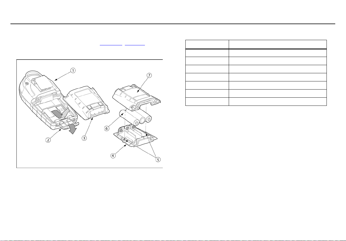
GasAlertMicro 5/PID/IR
User Manual
Replacing the Alkaline Batteries
To replace the alkaline batteries, refer to Figure 13., Table 20., and the
following steps 1-6.
Figure 13. Replacing the Alkaline Batteries
Table 20. Replacing the Alkaline Batteries
Item Description
1 Detector
2 Latch
3 Battery pack
4 Battery tray
5 Captive screws (2)
6 Alkaline batteries (3)
7 Battery shell
1. Deactivate the detector.
2. Open the latch on the bottom of the detector.
3. Remove the battery pack by lifting the bottom of the pack away from the detector.
4. On the battery pack, remove the two captive screws. Remove the battery shell from the battery tray.
5. Replace the three alkaline batteries.
6. Replace the battery pack and the captive screws.
7. Reinsert the battery pack and secure the latch.
82
Page 95
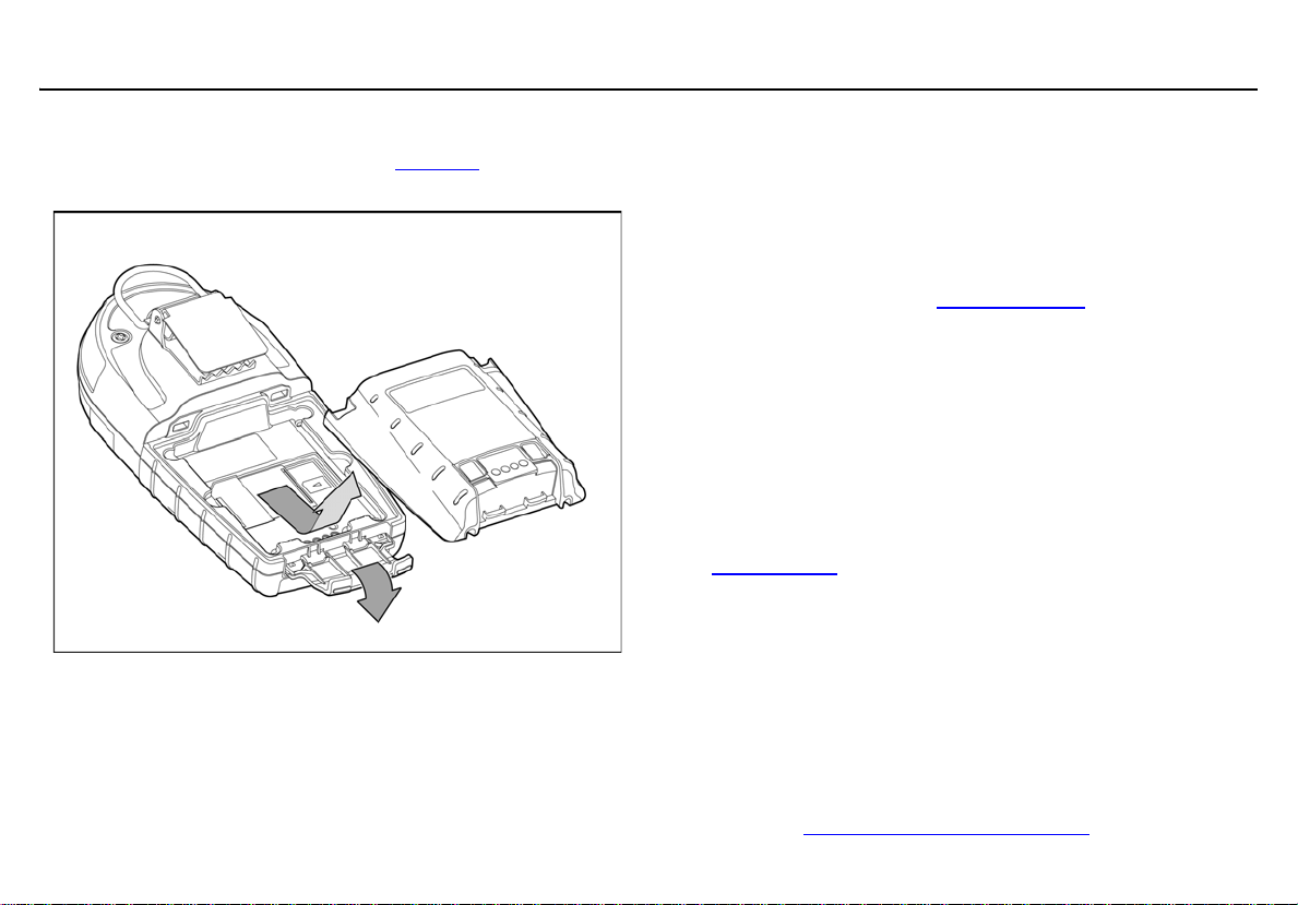
GasAlertMicro 5/PID/IR
Maintenance
Replacing the Lithium Battery Pack
To replace the lithium battery pack, refer to Figure 14. and the following
steps 1-4.
Figure 14. Replacing the Lithium Battery Pack
1. Deactivate the detector.
2. Open the latch on the bottom of the detector.
3. Remove the battery pack by lifting the bottom of the pack upward from the detector.
a Warning
Do not disassemble lithium battery packs. Read and
adhere to the cautions in Battery Cautions
4. Replace the battery pack with a fully charged lithium battery pack.
5. Close the latch.
.
Replacing a Sensor or Sensor Filter
a Warning
To avoid personal injury, only use sensors that are
specifically designed for the detector. Refer to
Specifications
Replace the sensor in a safe and non-hazardous area
that is free of hazardous gas
Each sensor has a high degree of resistance to common vapors and
gases. To clear a sensor, place the detector in a clean environment
and wait 10 to 30 minutes.
Do not expose a sensor to vapors from organic solvents such as paint
thinners and acetone. For a list of common products that can damage
sensors, refer to Sensor Poisons and Contaminants
.
a Caution
.
83
Page 96

GasAlertMicro 5/PID/IR
User Manual
For sensor problems, refer to Troubleshooting. To replace a sensor or sensor filter, refer to Figure 15., Table 21., and
the following procedures 1-7.
Figure 15. Replacing a Sensor or Sensor Filter
Note
Detectors that are configured for 1, 2, 3, or 4 gases may
contain a dummy sensor in one of the four sensor locations.
84
Page 97

GasAlertMicro 5/PID/IR
Maintenance
Table 21. Replacing a Sensor or Sensor Filter
Item Description
1 Sensor cover
2 Sensor filter
3 Sensors
4 Detector
5
1. Deactivate the detector.
2. Remove the two machine screws on the rear shell and then remove the sensor cover or pump module.
3. Remove the sensor filter and/or the sensor(s).
4. Insert the new filter and/or sensor. Ensure the sensor posts are aligned correctly.
5. Re-assemble the detector.
6. If the sensor is changed, such as SO
must be reconfigured. Refer to Sensors
option.
7. A sensor that has been replaced must be calibrated immediately. Refer to Calibration and Setting Alarm Setpoints
Machine screws (2)
to an H2S, the detector
2
in the Te ch Mo d e
.
Photoionization Detector (PID)
Clean or Replace the Lamp
The PID lamp must be cleaned regularly. Use only the cleaning kit
that is supplied by BW Technologies by Honeywell.
To clean the PID lamp, refer to the illustrations and procedures that
are provided with the PID Lamp Cleaning Kit. To order the kit, refer
to Replacement Parts and Accessories
a Caution
To ensure proper maintenance and continued accurate
readings from the sensor, use only the PID Lamp
Cleaning Kit that is supplied by BW Technologies by
Honeywell.
Table 22. Parts of the PID sensor
Item Description
1 PID sensor
2 Diffusion barrier
3 Sensor cover
4 Electrode stack
5
Lamp
.
85
Page 98
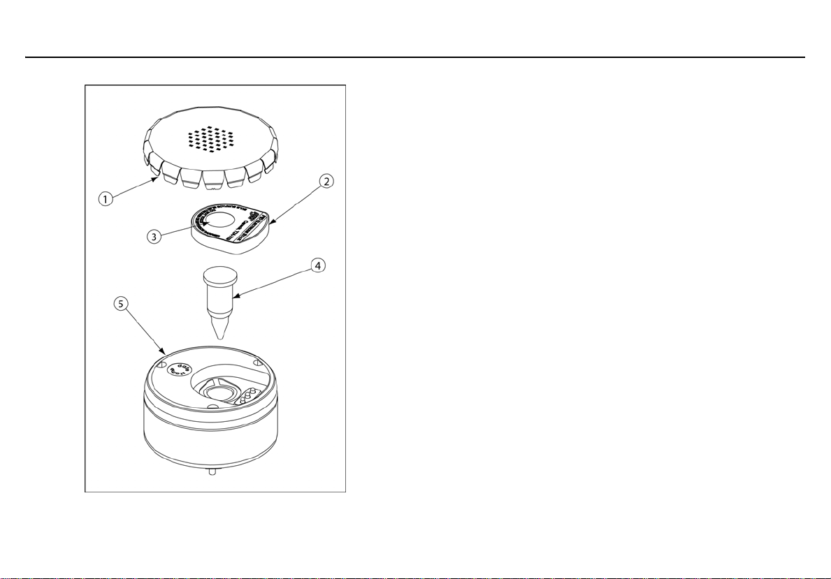
GasAlertMicro 5/PID/IR
User Manual
Replace the Lamp
Replace the lamp when it falls below the acceptable level. Possible
indicators that the lamp requires replacement are as follows:
• The detector will not calibrate.
• The startup self-test fails.
• The ppm levels are incorrect.
To replace the lamp, refer to the illustrations and procedures in the
PID Lamp Cleaning Kit.
If required, contact BW Technologies by Honeywell for more information.
86
Figure 16. Parts of the PID
Page 99

Replace the Electrode Stack
Replace the electrode stack when it is contaminated. To replace
the electrode stack, refer to Table 22.
procedures.
, Figure 16., and the following
a Caution
Ensure your fingers do not make contact with the
diffusion barrier or the electrodes on the underside of
the stack.
1. Remove the sensor cover.
2. Remove the old electrode stack.
3. Insert the new electrode stack.
4. Replace the sensor cover.
WEEE Battery Directive
Failure to comply with the following battery removal and disposal instructions may result in battery shorting, battery leakage, and/or other damage. Ensure a qualified technician completes the following procedures.
Removal and Disposal of the Battery Pack
To remove the alkaline batteries, refer to steps #1 to #3 in Replacing the
Alkaline Batteries on page 82.
To remove the lithium battery pack, refer to steps #1 and #2 in
the Lithium Battery Pack on page 83.
Dispose of the battery pack according to local laws.
Replacing
Removal and Disposal of the Coin Cell
GasAlertMicro 5/PID/IR
Maintenance
87
Page 100

GasAlertMicro 5/PID/IR
User Manual
Item Description
1 Diffusion cap
2 Sensor filter
3Sensors
4 Front shell
5 Sensor board
6 Back shell
7 Machine screws (for diffusion cap)
8 Battery pack
9 Datalog card
10 Machine screws (for rear shell)
The detector contains a coin cell to power the real-time clock. Only a
qualified technician should complete the following procedure.
1. Deactivate the detector.
2. Open the latch on the bottom of the detector.
3. Remove the battery pack by lifting the bottom of the pack upward from the detector.
4. Remove the MMC card.
5. Remove the two machine screws on the rear shell and then remove the diffusion cap or pump module.
6. Remove the sensors.
7. Remove the four machine screws in the battery pack cavity.
8. Remove the rear shell.
9. The coin cell sits on the sensor board.
Gently remove the sensor board.
10. The coin cell is connected to the board by four leads. Clip the four leads individually to remove the coin cell.
a Caution
Do not touch two or more leads while disconnecting the
battery cell.
11. Dispose of the coin cell according to local laws.
Note
Image above shows three of the four battery leads that must be
clipped.
88
 Loading...