

Page 1

GasAlertMicro
H2S, CO, O2, SO2, Combustibles
1, 2, 3, and 4 Gas Detectors
User Manual
Page 2

Limited Warranty & Limitation of Liability
BW Technologies LP (BW) warrants this product to be free from defects in material and workmanship under normal use and service for a period of two years,
beginning on the date of shipment to the buyer. This warranty extends only to the sale of new and unused products to the original buyer. BW’s warranty
obligation is limited, at BW’s option, to refund of the purchase price, repair, or replacement of a defective product that is returned to a BW authorized service
center within the warranty period. In no event shall BW’s liability hereunder exceed the purchase price actually paid by the buyer for the Product.
This warranty does not include:
a) fuses, disposable batteries or the routine replacement of parts due to the normal wear and tear of the product arising from use;
b) any product which in BW’s opinion, has been misused, altered, neglected or damaged by accident or abnormal conditions of operation, handling or use;
c) any damage or defects attributable to repair of the product by any person other than an authorized dealer, or the installation of unapproved parts on the
product; or
The obligations set forth in this warranty are conditional on:
a) proper storage, installation, calibration, use, maintenance and compliance with the product manual instructions and any other applicable
recommendations of BW;
b) the buyer promptly notifying BW of any defect and, if required, promptly making the product available for correction. No goods shall be returned to BW
until receipt by the buyer of shipping instructions from BW; and
c) the right of BW to require that the buyer provide proof of purchase such as the original invoice, bill of sale or packing slip to establish that the product is
within the warranty period.
THE BUYER AGREES THAT THIS WARRANTY IS THE BUYER’S SOLE AND EXCLUSIVE REMEDY AND IS IN LIEU OF ALL OTHER WARRANTIES,
EXPRESS OR IMPLIED, INCLUDING BUT NOT LIMITED TO ANY IMPLIED WARRANTY OF MERCHANTABILITY OR FITNESS FOR A PARTICULAR
PURPOSE. BW SHALL NOT BE LIABLE FOR ANY SPECIAL, INDIRECT, INCIDENTAL OR CONSEQUENTIAL DAMAGES OR LOSSES, INCLUDING
LOSS OF DATA, WHETHER ARISING FROM BREACH OF WARRANTY OR BASED ON CONTRACT, TORT OR RELIANCE OR ANY OTHER THEORY.
Since some countries or states do not allow limitation of the term of an implied warranty, or exclusion or limitation of incidental or consequential damages, the
limitations and exclusions of this warranty may not apply to every buyer. If any provision of this warranty is held invalid or unenforceable by a court of competent
jurisdiction, such holding will not affect the validity or enforceability of any other provision.
BW Technologies LP BW America BW Europe
2840 – 2nd Ave. SE 3279 West Pioneer Parkway 101 Heyford Park,
Calgary, AB Arlington, TX Upper Heyford, Oxfordshire
Canada T2A 7X9 USA 76013 United Kingdom OX25 5HA
Page 3

Table of Contents
Title Page
Introduction............................................................................................................................................ 1
Contacting BW Technologies................................................................................................................ 2
Safety Information - Read First .............................................................................................................2
Getting Started ......................................................................................................................................6
Parts of the GasAlertMicro Detector ..................................................................................................... 7
Installing Alkaline Batteries .................................................................................................................10
Activating the Detector........................................................................................................................ 10
Self-Test............................................................................................................................... 10
Self-Test Pass .....................................................................................................................14
Self-Test Fail........................................................................................................................ 14
Battery Test.......................................................................................................................... 14
Datalogger Operation (optional) .......................................................................................... 14
Deactivating the Detector.................................................................................................................... 15
Confidence Beep................................................................................................................................. 15
User Options Menu ............................................................................................................................. 16
Software Level ..................................................................................................................... 17
Finish Options...................................................................................................................... 17
Latching Alarms ................................................................................................................... 17
Safe Display......................................................................................................................... 18
Combustible Sensor Measuring Selection ..........................................................................19
French.................................................................................................................................. 21
German ................................................................................................................................21
Spanish ................................................................................................................................22
i
Page 4

GasAlertMicro
User Manual
Title Page
Portuguese........................................................................................................................... 22
English ................................................................................................................................. 23
Sensor Options ....................................................................................................................23
Pass Code Protection .......................................................................................................... 25
Automatic Oxygen Calibration .............................................................................................27
Span Concentration ............................................................................................................. 28
STELCalculation Period.......................................................................................................29
Stealth Mode........................................................................................................................30
Automatic Backlight .............................................................................................................31
MicroBatt Mode....................................................................................................................31
Bump Due Reminder ...........................................................................................................32
Adjust Clock ......................................................................................................................... 33
Logger Rate .........................................................................................................................34
Alarms .............................................................................................................................................35
Gas Exposures Computed................................................................................................... 38
Viewing Gas Exposures....................................................................................................... 38
Gas Alarm Setpoints............................................................................................................ 39
Resetting Gas Alarm Setpoints............................................................................................39
Stopping a Gas Alarm.......................................................................................................... 39
Sensor Alarm .......................................................................................................................40
Low Battery Alarm................................................................................................................ 40
Automatic Shutdown Alarm .................................................................................................40
Calibration and Setting Alarm Setpoints .............................................................................................40
Calibration Guidelines..........................................................................................................40
Diagnostics Protection ......................................................................................................... 41
Attaching the Gas Cylinder to the Detector .........................................................................42
Calibration Procedures ........................................................................................................43
ii
Page 5

Title Page
MultiMediaCard (MMC) ....................................................................................................................... 50
MultiMediaCard Troubleshooting ........................................................................................ 51
Recovering Data Files .........................................................................................................51
Direct Import to Compatible Programs ................................................................................ 52
Determining Application Compatibility................................................................................. 53
Descriptions of Line Examples ............................................................................................ 56
Maintenance........................................................................................................................................ 56
Inserting the MultiMediaCard (MMC)................................................................................... 57
Replacing the Batteries ....................................................................................................... 57
Replacing a Sensor or Sensor Filter ................................................................................... 59
Troubleshooting ..................................................................................................................................62
Replacement Parts and Accessories.................................................................................................. 65
Specifications ...................................................................................................................................... 69
iii
Page 6

GasAlertMicro
User Manual
iv
Page 7

List of Tables
Table Title Page
1. Gases Monitored ................................................................................................................... 1
2. International Symbols ............................................................................................................ 5
3. GasAlertMicro Detector .........................................................................................................7
4. Display Elements ................................................................................................................... 8
5. Pushbuttons........................................................................................................................... 9
6. Alarms..................................................................................................................................35
7. Computed Gas Exposures .................................................................................................. 38
8. Gas Alarm Setpoints............................................................................................................ 39
9. Sample Factory Set Alarm Setpoints................................................................................... 39
10. Attaching the Gas Cylinder to the Detector ......................................................................... 42
11. Datalogger Status Codes .................................................................................................... 54
12. CSV File Example................................................................................................................ 55
13. Replacing the Batteries ....................................................................................................... 58
14. Torque Specs ...................................................................................................................... 60
15. Replacing a Sensor or Sensor Filter ................................................................................... 60
16. Troubleshooting Tips ........................................................................................................... 62
17. Replacement Parts and Accessories .................................................................................. 65
v
Page 8

GasAlertMicro
User Manual
vi
Page 9

List of Figures
Figure Title Page
1. GasAlertMicro Detector .........................................................................................................7
2. ................................................................................................................... 8Display Elements
3. ......................................................................................................... 10Installing the Batteries
4. ......................................................................... 42Attaching the Gas Cylinder to the Detector
5. ................................................................................... 57Inserting the MultiMediaCard (MMC)
6. ....................................................................................................... 58Replacing the Batteries
7. ................................................................................... 61Replacing a Sensor or Sensor Filter
vii
Page 10

GasAlertMicro
User Manual
CAUTION: FOR SAFETY REASONS, THIS EQUIPMENT
MUST BE OPERATED AND SERVICED BY QUALIFIED
PERSONNEL ONLY. READ AND UNDERSTAND THE
USER MANUAL COMPLETELY BEFORE OPERATING OR
SERVICING.
GasAlertMicro Multi-Gas Detector
Standard instrument is equipped with integral concussionproof boot and internal vibrator alarm.
GasAlertMicro with User Downloadable Datalogger
Provides full time continuous datalogging while the
instrument is operating. Data is saved on a convenient
MultiMediaCard (MMC) and can be removed and
downloaded by the user. Data is imported into standard
office software (Microsoft® Excel, Access etc.). Wraparound
memory ensures the most recent data is always saved.
Accessing Test Results with Fleet Manager
To access and view test results using the Fleet Manager
software application, please refer to the Fleet Manager
Support CD.
Accessing Test Results with EDM
To access and view test results using the Excel Datalog
Manager (EDM) software application, please refer to the
EDM CD.
viii
Page 11

GasAlertMicro
Introduction
a Warning
To ensure your personal safety, read “Safety
Information” before using the detector.
The GasAlertMicro gas detector (“the detector”) is designed
to warn of hazardous gas at levels above user-selectable
alarm setpoints.
The detector is a personal safety device. It is your
responsibility to respond properly to the alarm.
Table 1 lists the gases that are monitored.
Table 1. Gases Monitored
Gas Detected Unit of Measure
Hydrogen sulfide (H2S) parts per million (ppm)
Carbon monoxide (CO) parts per million (ppm)
Oxygen (O2) percent by volume (%)
Combustible gases
field selectable for:
Sulfur dioxide (SO2) parts per million (ppm)
a) percent of lower
explosive limit (% LEL)
b) percent by volume
methane 0-5.0% v/v
1
Page 12

GasAlertMicro
User Manual
Contacting BW Technologies
To contact BW Technologies call:
USA: 1-888-749-8878
Canada: 1-800-663-4164
Europe: +44 (0) 1869 233004
Other countries: +1-403-248-9226
Address correspondence to:
BW Technologies LP
2840 – 2 Avenue S.E.
Calgary, AB T2A 7X9
CANADA
Email us at:
Visit our website at:
ISO 9001
info@bwtnet.com
www.gasmonitors.com
Safety Information - Read First
Use the detector only as specified in this manual otherwise
the protection provided by the detector may be impaired.
International symbols used on the detector and in this
manual are explained in Table 2.
Read the Warnings and Cautions on the following pages
before using the detector.
ec Note
This instrument contains batteries. Do not mix
with the solid waste stream. Spent batteries
should be disposed of by a qualified recycler or
hazardous materials handler.
2
Page 13

GasAlertMicro
Safety Information - Read First
a Cautions
⇒ Warning: Substitution of components may impair Intrinsic Safety.
⇒ Do not use the detector if it is damaged. Inspect the case before use. Look for cracks and missing parts.
⇒ If the detector is damaged or parts are missing, contact
⇒ Ensure the battery compartment is locked in place before operating the detector.
⇒ Use only a sensor that is specifically designed for the GasAlertMicro model. Refer to
Accessories.
⇒ Calibrate the detector before first-time use and continue on a regular schedule. The schedule will depend upon
use and sensor exposure to poisons and contaminants. BW recommends that calibration be performed a
minimum of once every 180 days (6 months).
⇒ BW recommends to “bump test” the sensors, before each day’s use, to confirm their ability to respond to gas
by exposing the detector to a gas concentration that exceeds the high alarm setpoints. Manually verify that the
audible and visual alarms are activated. Calibrate if the readings are not within the specified limits.
⇒ BW recommends that the combustible sensor be checked with a known concentration of calibration gas after
any known exposure to catalyst contaminants/poisons (sulfur compounds, silicon vapors, halogenated
compounds, etc.).
⇒ The combustible sensor is factory calibrated to 50% LEL methane. If monitoring a different combustible gas in
the % LEL range, calibrate the sensor using the selected gas. High off-scale % LEL or % v/v methane readings
may indicate an explosive concentration.
⇒ Protect the combustible sensor from exposure to lead compounds, silicones, and chlorinated hydrocarbons.
Selected organic vapors (ie. leaded gasoline and halogenated hydrocarbons) may temporarily inhibit sensor
performance. However, in most cases the sensor will recover after calibration.
BW Technologies immediately.
Replacement Parts and
3
Page 14

GasAlertMicro
User Manual
aCautions (cont.)
⇒ Any rapid up-scaling reading that is followed by a declining or erratic reading can indicate a gas concentration
beyond upper scale limit. It may be hazardous!
⇒ Use only recommended AA alkaline or NiMH batteries that are properly charged and installed in the detector
case. Refer to
⇒ Charge NiMH batteries using the recommended charger only. Do not use any other charger. Failure to observe
this precaution can lead to fire or explosion.
⇒ Do not change or charge batteries in a hazardous location. Doing so will impair the Intrinsic Safety of the unit
and can lead to fire or explosion.
⇒ Read and observe all instructions and precautions that are provided with the charger. Failure to do so can
result in fire, electric shock, or other forms of personal injury and property damage.
⇒ Extended exposure of the GasAlertMicro to high concentrations of combustible gases and air may stress a
detector element, which can seriously affect its performance. If an alarm occurs due to high concentration of
combustible gases, recalibrate immediately. If required, replace the sensor.
⇒ Do not test the combustible sensor response with a butane cigarette lighter. This will damage the sensor.
⇒ Do not expose the detector to electrical shock or severe mechanical shock.
⇒ Do not attempt to disassemble, adjust, or service the detector unless instructions in the User Manual are
provided to perform a procedure, or if a part is listed as a replacement part. Use only
replacement parts.
⇒ Do not immerse the detector in liquids.
⇒ The detector Warranty will be voided if a customer, personnel, or third parties damage the detector during
repair attempts. Any Non-BW Technologies repair/service attempts will void this Warranty.
Replacement Parts and Accessories.
BW Technologies
4
Page 15

GasAlertMicro
Safety Information - Read First
Table 2. International Symbols
Symbol Meaning
n
g
X
BAM
ATEX
IECEx
Approved to both U.S. and Canadian Standards by the Canadian Standards Association
European Explosives Protection
Conforms to European Union Directives
BAM performance verification to European Performance Standards
Conforms to European ATEX Directives
International Electrotechnical Commission Scheme for Certification to Standards for Electrical Equipment for
Explosive Atmospheres
Type approved by ABS America for use aboard cargo vessels
5
Page 16

GasAlertMicro
User Manual
Getting Started
Confirm that the standard items listed below are included
with your detector. If the detector is damaged or parts are
missing, contact the place of purchase immediately.
• Batteries (two replaceable alkaline cells, four NiMH
rechargeable cells, or one GA MicroBatt cell)
• Charger (if applicable) one AC/DC line charger or one
GA MicroBatt charger
• O
sensor
2
• Combustible sensor
• Four-gas units - one H
• Three-gas units - one applicable toxic sensor.
• Calibration hose and cap
• Quick reference guide
• CD
S/CO sensor (dual sensor)
2
To order replacement parts, refer to Replacement Parts and
Accessories.
Each detector is manufactured with sensors installed. Refer
to
Maintenance before installing the batteries.
For information about the features and functions of the
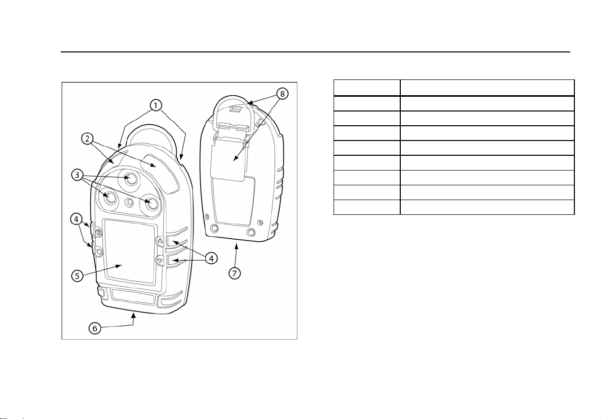
detector, refer to the following figures and tables:
• Figure 1 and Table 3: GasAlertMicro Detector
• Figure 2 and Table 4: Display Elements
• Table 5: Pushbuttons
6
Page 17
GasAlertMicro
Getting Started
Parts of the GasAlertMicro Detector
Figure 1. GasAlertMicro Detector
Table 3. GasAlertMicro Detector
Item Description
1
2
3
4
5
6
7
8
Audible alarms
Visual alarm bars
Sensors
Pushbuttons
Display
Battery compartment
Datalogger (optional)
Alligator clip
7
Page 18
GasAlertMicro
User Manual
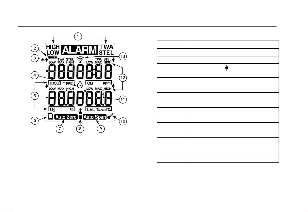
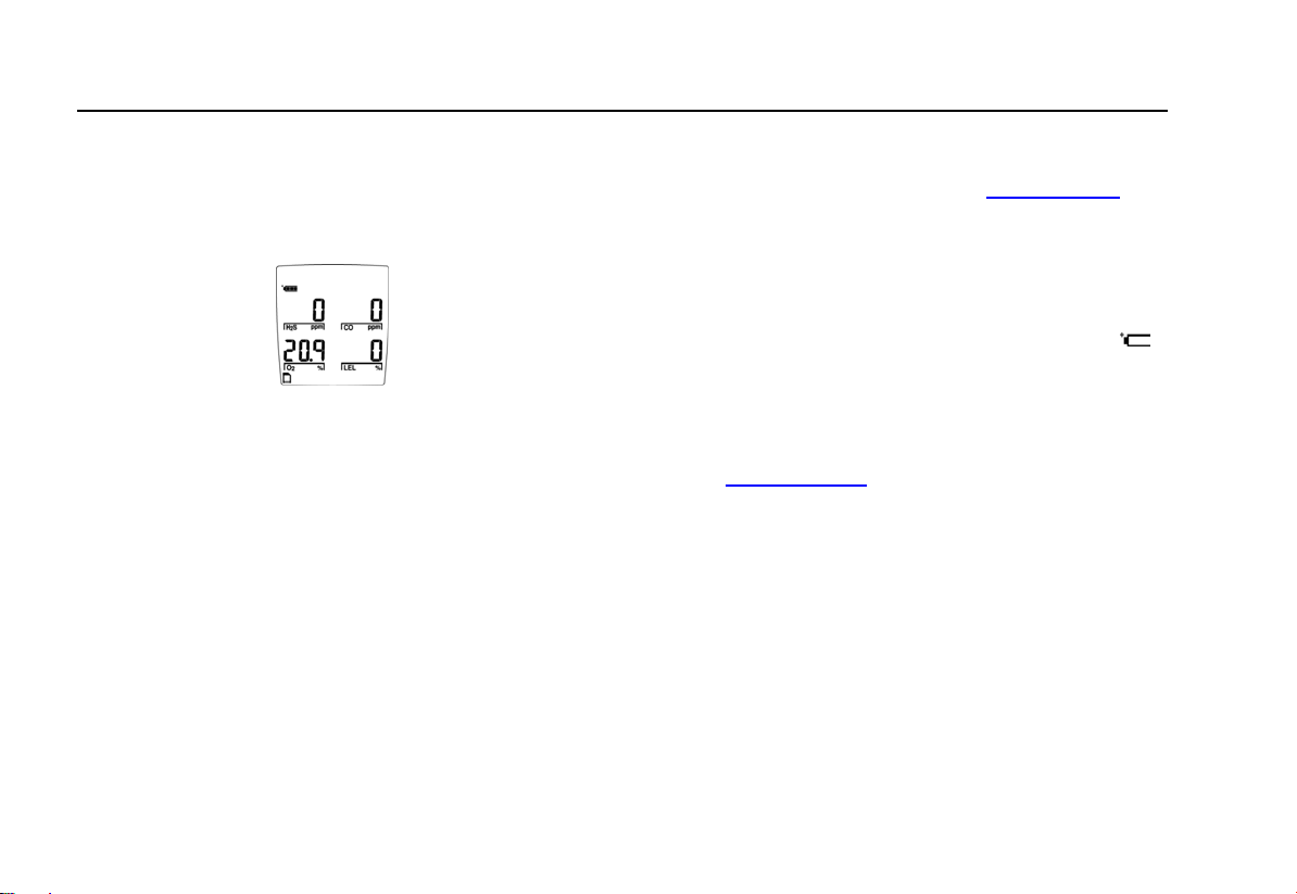
Figure 2. Display Elements
Note
When an alarm condition occurs and there is
insufficient light to view the LCD, the backlight
automatically activates for 10 seconds. Push any
pushbutton to reactivate the backlight in low-light
conditions. The detector is shipped with the auto
backlight option enabled.
Table 4. Display Elements
Item Function
1
2
3
Alarm condition
Battery life indicator
Button indicator
(displays when a button
press is allowed).
4
5
6
7
8
9
10
11 Real time calendar (date, month, year)
Clock
Gas identifier bars
Datalogger card indicator (
Automatically zero sensor
Gas cylinder
Automatically span sensor
Pass code lock
optional)
12 Alarm condition (low, high TWA, STEL, or
multi-gas), or view TWA, STEL, and
maximum (MAX) gas exposures
13 Future use
8
Page 19

GasAlertMicro
Getting Started
Table 5. Pushbuttons
Pushbutton Description
A
G
H
C
• To activate the detector press
• To deactivate the detector, press
• To enable/disable the confidence beep, when the detector is deactivated press and hold
C, press A. This enables/disables the confidence beep while activating the start-up process.
• To bypass calibration after auto zero press
• To access the software level information, press
• To increment a displayed value or to scroll up press
• To enter the user options menu, press
• To clear the TWA, STEL, and MAX gas exposure readings, press
• To quickly scroll through options press and hold
• To decrement a displayed value or scroll down press
• To initiate calibration and enter alarm setpoints, press
• To quickly scroll through options press and hold
• To view the TWA, STEL, and MAX hold readings, press
• To acknowledge latched alarms press
• To acknowledge a failed bump test screen press
• At any time after auto zero, and only prior to calibration gas being detected, press
and proceed to alarm setpoints.
A.
A and hold until OFF displays (approximately 5 seconds).
C. While holding
A.
A at any time from any of the user options.
G.
G and H simultaneously and hold for 5 seconds.
C and G simultaneously.
G.
H.
C and H simultaneously and hold for 5 seconds.
H.
C.
C.
C.
C to bypass calibration
9
Page 20
GasAlertMicro
User Manual
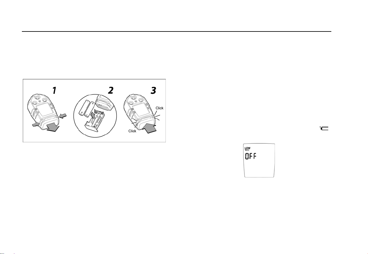
Installing Alkaline Batteries
If the detector uses alkaline batteries they need to be
installed before activation. Refer to the following figure and
instructions to install the batteries.
Figure 3. Installing the Batteries
1. Press the two release tabs on the detector.
2. Remove the battery tray by pulling the bottom away
from the detector.
3. Install the alkaline batteries that are included with
the detector. Polarity markings are shown inside the
battery tray.
4. Insert the battery tray into the detector. Push until
the release tabs click.
Activating the Detector
To activate the detector and only in an area that is free from
hazardous gases (20.9% oxygen), press
Self-Test
When the detector is activated it performs several system
tests. Verify that all tests have been performed prior to using
the detector.
The following tests are listed in the order they are performed
and displayed on the detector.
1. Low Battery Test:
LOW
flashes and the LCD displays OFF.
If battery power is extremely low,
Replace the batteries and restart the detector before
proceeding.
A.
10
Page 21
GasAlertMicro
Activating the Detector
Note
At any time during activation, if the battery power is
extremely low the detector will shut down. For more
information, refer to
2. Detector Elements Test: All of the display elements
briefly turn on during start-up.
Confidence Beep.
3. Date Test (optional): This test displays the day of the
week (1-7), the time (hour/minutes), and the date
(day/month/year).
4. Backlight Test: The backlight turns on and then off.
5. Alarm Setpoints Test: The TWA, STEL, low, and high
alarm setpoints display.
Note
Alarm setpoints can vary according to region. For
more information, refer to
Setpoints.
Resetting Gas Alarm
11
Page 22
GasAlertMicro
User Manual
6. Calibration Status Test: Calibration status displays the
number of days remaining before calibration is due.
If calibration is overdue, an audible alarm sounds and the
LCD displays the number of days the calibration is overdue.
To acknowledge the alarm, complete the following:
Press
C to acknowledge and silence the audible alarm.
Once in normal operation mode, calibrate the detector. Refer
to
Calibration and Setting Alarm Points.
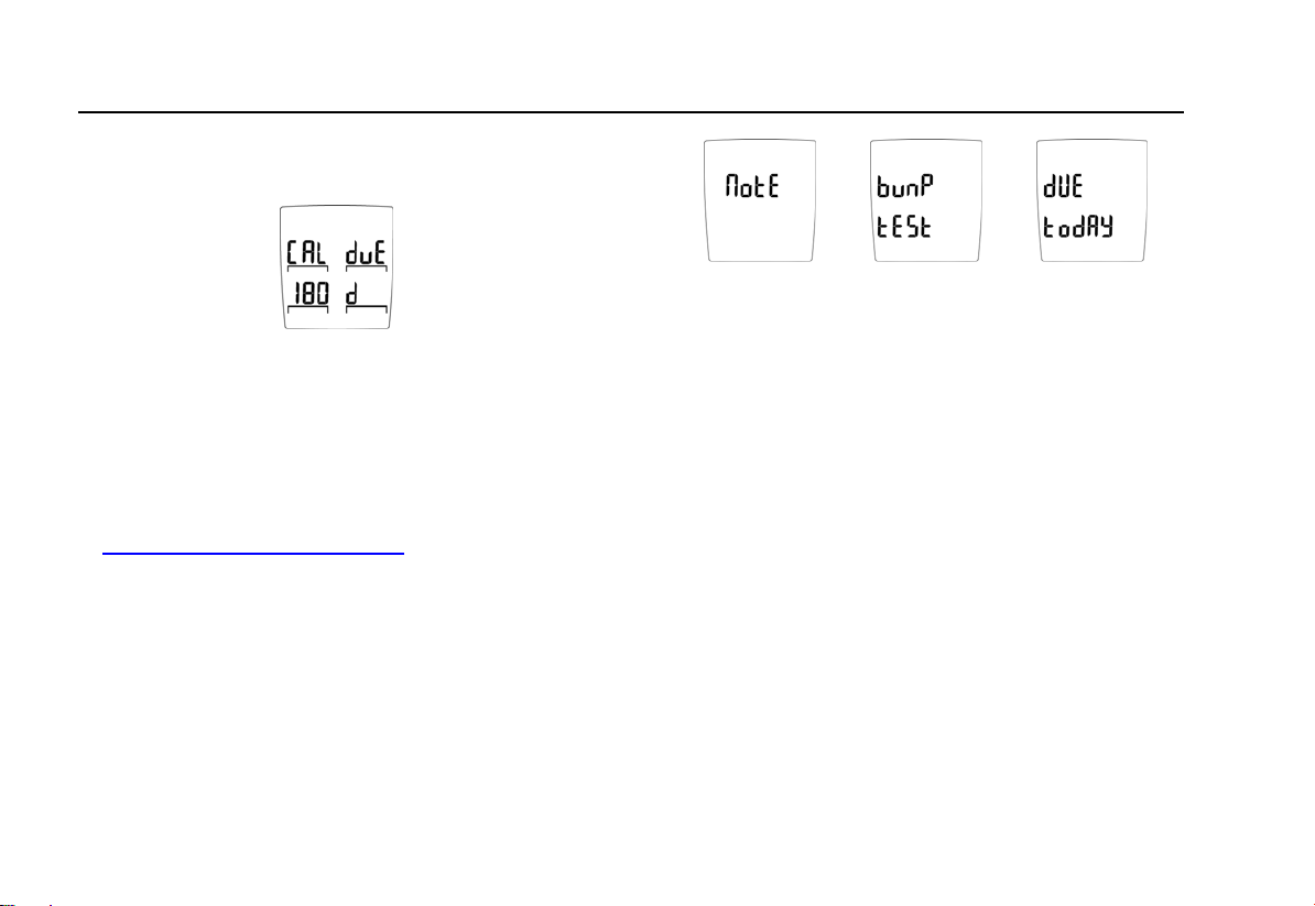
7. Bump Check Reminder Test (optional): The detector
can be enabled to remind when a bump check is due. If this
feature is enabled and bump check is due, the LCD displays
the following screens:
The detector beeps twice, flashes once, and emits one
vibration.
1. To temporarily bypass the reminder, hold the
button for two seconds.
Note
Bypassing the reminder is temporary. The reminder
will display and alarm the next time the detector is
activated.
2. To bump the detector using the MicroDock II
Automatic Test and Calibration Station, refer to the
MicroDock ll User Manual.
If the detector has recently failed a bump test in the
MicroDock II, the detector’s LCD displays nOtE: bumP tESt
hAS FAiLEd.
C
12
3. Press
4. From the MicroDock ll run another bump check.
C to acknowledge the warning.
Page 23

GasAlertMicro
Activating the Detector
8. Sensor Test: The LCD displays tESt when the detector
tests the sensors.
If a sensor fails the self-test, the detector indicates an alarm
by beeping, flashing, and vibrating. The LCD displays
SEnSor _ hAS FAiLEd and lists which sensor has failed.
Sensor 1: CO/H2S or SO
Sensor 2: LEL
Sensor 3: Oxygen
9. MultiMediaCard (MMC) Test: (
MMC card installed, the LCD displays a scrolling error
message.
2
optional): If there is no
The card is not required for operation; the message is a
reminder only.
10. Oxygen Sensor Test: Unless this feature is disabled,
the oxygen sensor is calibrated automatically.
If the automatic oxygen calibration feature has been
disabled, the LCD displays the O
calibration current mode
2
screen.
13
Page 24
GasAlertMicro
User Manual
Self-Test Pass
After the self-test has been completed and any alarms have
been acknowledged, the detector begins normal operation.
The LCD then displays the current ambient gas readings.
The detector begins recording immediately. It records the
• maximum (MAX) gas exposure,
• records the short-term exposure levels (STEL), and
• calculates the time-weighted average (TWA)
exposures.
When the air is at acceptable levels, and if the safe option is
enabled, SAFE scrolls across the screen continually while in
normal operating mode. SAFE does not display while
functions are being performed.
Note
This option is disabled in stealth mode.
Self-Test Fail
If the detector fails the self-test, refer to Troubleshooting.
Battery Test
The detector tests the batteries upon activation and
continuously thereafter. The battery power icon
at all times while in normal operation mode. If the battery
voltage is low, the detector displays the low battery icon
LOW and activates the low battery alarm (beeps every 10
seconds if the confidence beep is disabled).
If the confidence beep option is enabled, the confidence
beep stops if the battery power is low. For more information,
refer to
Confidence Beep.
If the battery voltage is extremely low, the detector performs
an automatic shutdown.
I displays
Datalogger Operation (optional)
The datalogger operation is automatic and requires no
settings.
When the MultiMediaCard (MMC) is inserted in the detector,
the MMC card icon
operation mode.
S displays continuously while in normal
14
Page 25

GasAlertMicro
Deactivating the Detector
The card is not required for operation; however, a warning
message displays during activation as a reminder that the
card is not inserted.
- Error - initially displays and no dAtA cArd installed then
scrolls across the screen. After the message displays, the
detector returns to normal operating mode. Insert the MMC
card if required.
Deactivating the Detector
To deactivate the detector, complete the following:
A and hold until OFF displays (approximately 5
Press
seconds).
The audible alarm beeps four times, the visual alarm flashes
four times, and the detector vibrates.
Note
If
A is not held down until OFF displays, the
detector will remain activated.
Confidence Beep
The confidence beep is used to confirm that the detector is
activated and the batteries have sufficient power to respond
to a hazardous level of gas.
When battery power is sufficient, the audible alarm beeps
twice every 15 seconds. The confidence beep stops when
battery power is too low.
The confidence beep can be enabled or disabled. To
enable/disable the confidence beep, complete the following:
Before activating the detector, press and hold
holding
As the start-up process begins, the confidence beep current
mode changes.
The normal activating/deactivating process does not
automatically enable/disable the confidence beep. It remains
in the selected mode until it is changed.
C, press A.
Note
The LCD does not display confirmation to indicate
the current mode of the confidence beep.
C. While
15
Page 26

GasAlertMicro
User Manual
User Options Menu
The user options menu provides access to twenty-one user
selections.
Note
Not all user options are available for detectors that
do not have the datalogger feature.
To access the user options menu, complete the following:
1. To enter the user options menu, press
simultaneously and hold (approximately 5 seconds)
until the LCD displays USEr OPtionS.
G and H
NOTE
If the detector is pass code protected when USEr
OPtionS is entered, the LCD displays an error
message.
16
Following the USEr OPtionS screen, the FiniSh
OPtionS screen immediately displays.
Refer to Pass Code Protection to enter a pass
code.
2. Press
H or G to scroll through the options.
Press and hold
H or G to scroll through the
options quickly.
3. Press
C to select a required option.
4. When the required activities have been performed
for a selected option, the FiniSh OPtionS screen
automatically displays.
Page 27

GasAlertMicro
User Options Menu
5. Use G or H to select another option if required.
6. To exit the user options menu and return to normal
operation, use
and press
The button indicator arrow(s)
points toward the button(s) that are available for additional
activities. If additional activities cannot be performed for a
selected option, the arrow(s) does not display.
Using the
are described in the order they display on the
detector LCD.
G pushbutton, the following user options
Software Level
The software level provides information about the firmware
and the EEPROM version of the detector.
To view information about the firmware and EEPROM
version, complete the following:
From the user options menu, press
G or H to select FiniSh OPtionS
C.
display(s) on the LCD and
Note
A.
For more information, refer to the Specifications.
Finish Options
FiniSh OPtionS displays after accessing the USEr OPtionS
menu, after each user option function is completed, and is
used to exit the user options menu.
To exit the user options menu and return to normal operation,
from the FiniSh OPtionS screen, press
C.
Latching Alarms
The LAtchin ALArmS option is used to set parameters for
alarms, such as, an alarm persists until it is acknowledged by
the user.
Note
The detector is shipped with the latching alarm
option disabled.
17
Page 28

GasAlertMicro
User Manual
In the event of an alarm condition, and if the low and high
gas alarms are set to latch, the audible and visual alarms will
persist until the alarm is acknowledged.
To enable/disable the latched alarm option, complete the
following:
1. From the user options menu, use
G or H to scroll
to the LAtchin ALArmS option.
2. Press C to select the option.
The LCD displays the current mode (On or OFF)
and then returns to the FiniSh OPtionS screen.
or
3. Use
G or H to scroll to a new user option, or press
C to exit user options and return to normal
operating mode.
Safe Display
The SAFE dISPLAY option automatically notifies that only
normal ambient conditions exist and that there are no gas
hazards monitored. This option can be enabled or disabled.
If this option is enabled, when the detector is in normal
operating mode and when no hazards are measured, SAFE
scrolls across the LCD continually.
SAFE does not display while functions are being performed.
This option is automatically disabled in stealth
mode.
If any gas is present, such as
• readings are other than zero for toxic combustible
gas(es), or
• the oxygen reading is other than 20.9%,
the LCD displays the gas levels for all of the sensors. When
the levels return to normal, SAFE again scrolls across the
screen.
Note
18
Page 29

GasAlertMicro
User Options Menu
To enable/disable the safe display option, complete the
following:
1. From the user options menu, use
G or H to scroll
to the SAFE dISPLAY option.
2. Press C to select this option.
The LCD displays the current mode (On or OFF)
and then returns to the FiniSh OPtionS screen.
or
3. Use G or H to scroll to a new user option, or press
C to exit user options and return to normal
operating mode.
Combustible Sensor Measuring Selection
The LEL SEn unitS option is used to select how the
measurements are displayed. The options are 0-100% LEL
or 0-5.0% vol.
Note
The detector is shipped with the combustible
sensor set to measure and display combustible
gases in the 0-100% LEL (lower explosive limit)
range.
The detector can be set to measure and display methane in
the 0-5.0% by volume range.
Note
Percent by volume measurements apply to
methane only.
19
Page 30

GasAlertMicro
User Manual
To change the combustible sensor unit of measure, complete
the following:
1. From the user options screen, use
to the LEL SEn unitS option.
2. Press C to select the option.
An LEL current mode screen immediately displays
either vol or %.
20
G or H to scroll
or
PErcEnt bY vol – units are displayed by volume.
PErcEnt LEL – units are displayed by percent.
The LCD returns to the FiniSh OPtionS screen.
3. Use
G or H to scroll to a new user option, or press
C to exit user options and return to normal
operating mode.
Page 31

GasAlertMicro
User Options Menu
French
The AFFiche FrAnc option is used to convert all of the LCD
screens to display French text.
1. From the user options menu, use
to the AFFiche FrAnc option.
G or H to scroll
2. Press C to select the option.
The LCD automatically displays French text and
returns to the FiniSh OPtionS screen.
3. Use
G or H to scroll to a new user option, or press
C to exit user options and return to normal
operating mode.
German
The AnZEigE dEutSch option is used to convert all of the
LCD screens to display German text.
1. From the user options menu, use
to the AnZEigE dEutSch option.
G or H to scroll
2. Press C to select the option.
The LCD automatically displays German text and
returns to the FiniSh OPtionS screen.
3. Use
G or H to scroll to a new user option, or press
C to exit user options and return to normal
operating mode.
21
Page 32

GasAlertMicro
User Manual
Spanish
The FiJAr A ESPAnoL option is used to convert all of the
LCD screens to display Spanish text.
1. From the user options menu, use
to the FiJAr A ESPAnoL option.
G or H to scroll
2. Press C to select the option.
The LCD automatically displays Spanish text and
returns to the FiniSh OPtionS screen.
3. Use
G or H to scroll to a new user option, or press
C to exit user options and return to normal
operating mode.
Portuguese
The AdJuStE Portugu option is used to convert all of the
LCD screens to display Portuguese text.
1. From the user options menu, use
to the AdJuStE Portugu option.
G or H to scroll
2. Press C to select the option.
The LCD automatically displays Portuguese text
and returns to the FiniSh OPtionS screen.
3. Use
G or H to scroll to a new user option, or press
C to exit user options and return to normal
operating mode.
22
Page 33

GasAlertMicro
User Options Menu
English
The SEt to EngLiSh option is only available when the LCD
displays text in French, German, Spanish, or Portuguese.
1. Use
G or H to scroll to the SEt to EngLiSh
option.
2. Press C to select the option.
The LCD automatically displays English text and
returns to the FiniSh OPtionS screen.
3. Use
G or H to scroll to a new user option, or press
C to exit user options and return to normal
operating mode.
Sensor Options
The sensor options are used to temporarily disable a sensor
and the corresponding fail alarm.
The detector will continue to function normally. The disabled
sensor can be enabled again at any time. The sensor should
be replaced and enabled as soon as possible.
a Warning
Disabling an installed sensor configures the
detector to a 1, 2, or 3-gas unit. No protection is
provided for the gas targeted by the selected
sensor(s). Disabling a sensor should only be
performed with extreme caution.
To enable/disable a sensor, complete the following
procedures:
Note
The following procedures example refers to the
toggLE H2S SEn option. The procedures are the
same for all of the sensors.
23
Page 34

GasAlertMicro
User Manual
toggLE H2S SEn
(hydrogen sulfide sensor)
toggLE CO SEn
(carbon monoxide sensor)
toggLE LEL SEn
(combusible)
toggLE O2 SEN
(oxygen sensor)
Note
For the toggLE O2 CAL option, refer to
Calibration.
Automatic Oxygen
The sensor options available to select from are as follows:
To enable/disable the H
1. From the user options menu, use
to the toggLE H2S SEn option.
S sensor, complete the following:
2
G or H to scroll
2. Press C to select the option.
or
The LCD displays the current mode (On or OFF)
and then returns to the FiniSh OPtionS screen.
If all of the sensors are disabled, the following message
displays: ALL SEnSorS ArE diSAbLEd - ALL SEnSorS ArE
rESEt to on.
24
Page 35

GasAlertMicro
User Options Menu
If a sensor option is enabled on the LCD but the new sensor
is not installed on the detector, the following message
displays: H2S SEnSor not inStALLEd - SEnSor CAnnot bE
EnAbLEd.
3. Use
G or H to scroll to a new user option, or press
C to exit user options and return to normal
operating mode.
Pass Code Protection
The PASS Lock option is used to prevent access to the user
options and calibration/alarm setpoint procedure without a
pass code.
Note
For calibration, the pass code is requested after
auto zero is performed (if enabled).
If the detector is pass code protected, the key icon (
displays at the bottom of the LCD during start-up.
Note
The detector is shipped with the pass code
protection option disabled.
)
Enable/Disable Pass Code Protection
To enable/disable the pass code protect option, complete the
following:
1. From the user options menu, use
to the PASS Lock option.
G or H to scroll
2. Press C to select this option.
The detector emits two beeps and the LCD displays
if pass code protection is enabled or disabled.
or
The LCD displays the current mode (On or OFF)
and then returns to the FiniSh OPtionS screen.
Note
The pass code is provided on a separate card
inside the shipping container.
25
Page 36

GasAlertMicro
User Manual
Entering the Pass Code
If the pass code protected option is enabled and access to
the user options menu or calibration is attempted, the LCD
displays the following:
The LCD then immediately prompts for the pass code. The
following three screens display.
To enter the pass code, complete the following:
1. From the SEt-- COdE screen, use
G or H to scroll
to the correct pass code.
2. Press
C to confirm the pass code selection.
3. If the pass code is correct, access is granted and
the LCD automatically displays the FiniSh OPtionS
screen. Use
option(s).
G or H to scroll to the required user
If the pass code is incorrect or the correct pass
code is not confirmed within 10 seconds, the LCD
displays an error message.
The detector returns to normal operating mode for
an incorrect pass code.
For a correct pass code not confirmed within 10
seconds, the following error messages displays.
26
Page 37

GasAlertMicro
User Options Menu
The detector then returns to normal operating
mode.
4. Repeat steps 1-2. If the second attempt is
unsuccessful, confirm that the pass code is correct.
Automatic Oxygen Calibration
The toggLE O2 CAL is used to enable/disable oxygen (O2)
automatic calibration that is performed during start-up.
Note
The detector is shipped with the automatic O
calibration option enabled.
2
To enable/disable the automatic O
calibration option,
2
complete the following:
1. From the user options menu, use
G or H to scroll
to the toggLE O2 CAL option.
2. Press C to select the option.
The LCD displays the current mode (On or OFF)
and then returns to the FiniSh OPtionS screen.
or
3. Use G or H to scroll to a new user option, or press
C to exit user options and return to normal
operating mode.
27
Page 38

GasAlertMicro
User Manual
Span Concentration
The Set CAL SPAnS option is used to enter each sensor’s
span concentration value that is required for calibration.
Note
BW recommends that span concentration values be
set between specific ranges. Refer to
Calibration
and Setting Alarm Setpoints.
To modify the span concentration values, complete the
following:
1. From the user options menu, use
G or H to scroll
to the SEt CAL SPAnS option.
2. Press C to select and access the span
concentration values screen.
3. The H
S value is automatically selected to modify.
2
Use
G or H to scroll to the required value.
H2S Hydrogen sulfide
CO Carbon monoxide
LEL Lower explosive limit
Note
The span concentration values can only be
modified in the order they are presented in this
table. To bypass any concentration value, press
C
to confirm and automatically proceed to the next
value. Press
C to confirm the new value and
automatically proceed to the CO value.
Note
If a new value is not confirmed within 10 seconds,
an Err message replaces the selected value. The
previous value then displays and the detector
automatically proceeds to the next concentration
value.
To bypass the H
S value, only press C. The
2
detector automatically accepts the current value
and then proceeds to the CO value.
4. For the remaining values repeat step 3 to modify or
bypass.
28
Page 39

GasAlertMicro
User Options Menu
5. When each of the span concentration values have
been accepted, the LCD returns to the FiniSh
OPtionS screen.
6. Use
G or H to scroll to a new user option, or press
C to exit user options and return to normal
operating mode.
STELCalculation Period
The StEL PEriod option is used to adjust the short-term
exposure limit (STEL) calculation period (5-15 minutes).
Note
The detector is shipped with the STEL calculation
period set to 15 minutes.
To change the STEL calculation period, complete the
following:
1. From the user options menu, use
G or H to scroll
to the StEL PEriod screen.
Press C to select StEL PEriod and to access the STEL time
period screen.
2. Use G or H to scroll to the required time period
value (5-15). Press
C within 10 seconds to save
the new period change.
The LCD returns to the FiniSh OPtionS screen.
Note
If the new value is not entered and confirmed within
10 seconds, the LCD displays an error message.
3. Use G or H to scroll to a new user option, or press
C to exit user options and return to normal
operating mode.
29
Page 40

GasAlertMicro
User Manual
Stealth Mode
The StEAlth mode option is designed to ensure that the
GasAlertMicro is undetected in situations that require
concealment. This option is used to disable the
• audible alarms,
• visual alarms, and
• backlight.
Only the vibrate alarm remains enabled.
Note
The detector is shipped with the stealth mode
disabled.
To enable/disable the stealth mode, complete the following:
1. From the user options menu, use
G or H to scroll
to the StEAlth option.
2. Press C to select this option.
or
The LCD displays the current mode (On or OFF)
and then returns to the FiniSh OPtionS screen.
3. Use
G or H to scroll to a new user option, or press
C to exit user options and return to normal
operating mode.
30
Page 41

GasAlertMicro
User Options Menu
Automatic Backlight
The Auto bAcklit option is used to enable or disable the
automatic backlight of the detector. When enabled, press any
button to activate the backlight for 10 seconds, regardless of
the lighting condition.
Note
The detector is shipped with the automatic backlight
option enabled.
Backlight does not operate while in stealth mode.
To enable/disable the backlight, complete the following:
1. From the user options menu, use the
scroll to the Auto bAcklit option.
G or H to
2. Press C to accept the option.
The LCD displays the current mode (On or OFF)
and then returns to the FiniSh OPtionS screen.
or
3. Use G or H to scroll to a new user option, or press
C to exit user options and return to normal
operating mode.
MicroBatt Mode
The micro-bAt option verifies if the detector is using the GA
MicroBatt battery. The detector provides an On or OFF
option to choose between lower MicroBatt levels and normal
battery levels.
Note
If the detector is equipped with the rechargeable
battery, BW highly recommends that the MicroBatt
option be enabled. The MicroBatt factory default
setting is disabled.
31
Page 42

GasAlertMicro
User Manual
To enable the MicroBatt mode, complete the following:
1. From the user option menu, use
the micro-bAt option.
G or H to scroll to
2. Press C to select this option.
The detectopr beeps twice. The LCD displays the
current mode (On or OFF) and then returns to the
FiniSh OPtionS screen.
or
3. Use G or H to scroll to a new user option, or press
C to exit user options and return to normal
operating mode.
Bump Due Reminder
The bumP duE option is used to display a reminder during
startup if a bump test has not been performed within the
previous 24 hours.
Note
The detector is shipped with the bump due
reminder option disabled.
The bump test function can only be performed using the
MicroDock II Automatic Test and Calibration Station. Refer to
the MicroDock ll User Manual for detailed information.
To enable/disable the bump due reminder option, complete
the following:
1. From the user options menu, use
to the bumP duE option.
G or H to scroll
2. Press C to select this option.
32
Page 43

GasAlertMicro
User Options Menu
The LCD displays the current mode (On or OFF)
and then returns to the FiniSh OPtionS screen.
or
3. Use G or H to scroll to a new user option, or press
C to exit user options and return to normal
operating mode.
Adjust Clock
AdJuSt CLock is used to adjust the weekday (1-7), time
(hour/minute), and date (day/month/year) of the detector.
To change the time and/or date, complete the following:
1. From the user options menu, use
to the AdJuSt CLock option.
G or H to scroll
2. Press C to accept the option and access the
date/time screen.
:16 Minute
20: Hour
2 Day of the week
Monday = 1, Tuesday = 2,
Wednesday = 3 etc.
22 Day of the month
06 Month
Year
02
Note
The weekday, time, and date values can only be
changed in the order they are presented in this
table. To bypass any setting, press
detector automatically retains the current value and
advances to the next time/date option.
3. The minutes are automatically selected. Use G or
H to scroll to the required value. Press C to
confirm the new value and automatically advance to
the hour option.
C. The
33
Page 44

GasAlertMicro
User Manual
To bypass the minute options, only press C. The
detector automatically retains the current value and
advances to the hour option.
4. For the remaining time and date options, repeat
step 3 to change or accept the current value.
5. When each of the time and date values have been
accepted, the LCD returns to the FiniSh OPtionS
screen.
6. Use
G or H to scroll to a new user option, or press
C to exit user options and return to normal
operating mode.
Logger Rate
LoggEr rAtE is used to determine how often data is recorded
to the MMC card. The logger rate value ranges from 1-127
seconds.
Note
The datalogger is factory set to record a sample
every 5 seconds.
To adjust the datalogger sampling rate, complete the
following:
1. From the user options menu, use
to the LOggEr rAtE option.
G or H to scroll
34
2. Press C to accept this option.
3. To change the sampling rate, use H or G to scroll
to the required sample rate value and press
confirm the new value.
The LCD automatically returns to the FiniSh
OptionS screen.
Note
If a new sample rate is not selected and confirmed
within 10 seconds, the detector automatically exits
the Set
005 IntEr screen and displays the FiniSh
OPtionS screen.
C to
Page 45

GasAlertMicro
Alarms
Alarms
Table 6 provides information about the detector alarms and includes an example of each LCD screen as it appears when it is in an
alarm state.
Table 7 provides information about the computed gas exposures.
During an alarm condition, the LCD activates the backlight and displays the current ambient gas reading.
If more than one type or level of alarm exists at the same time, a multi-gas alarm occurs.
To change the factory-set alarm setpoints, refer to the section
Table 6. Alarms
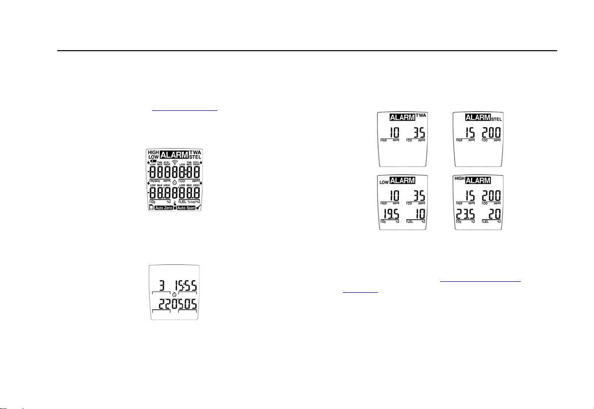
Alarms Display Alarms Display
Low Alarm:
• Slow tone and flash
•
L and target gas bar flash
• Vibrator alarm activates
STEL Alarm:
• Fast tone and flash
•
L and target gas bar flash
• Vibrator alarm activates
Calibration and Setting Alarm Setpoints.
High Alarm:
• Fast tone and flash
•
L and target gas bar flash
• Vibrator alarm activates
TWA Alarm:
• Slow tone and flash
•
L and target gas bar flash
• Vibrator alarm activates
35
Page 46

GasAlertMicro
User Manual
Alarms Display Alarms Display
Multi-Gas Alarm
• Alternating low and high alarm
tone and flash
•
L and target gas bars flash
• Vibrator alarm activates
Table 6. Alarms (cont.)
Over Range Alarm:
(Over Level Exposure)
• Fast tone and flash
•
L and target gas bar flash
• Vibrator alarm activates
Sensor Alarm:
• Slow tone and flash
•
L and gas bar(s) flash
• Vibrator alarm activates
36
Confidence Beep:
• two fast beeps every 15 seconds.
Page 47

GasAlertMicro
Alarms
Table 6. Alarms (cont.)
Alarms Display Alarms Display
Automatic Shutdown Alarm:
• eight beeps and flashes
•
LOW displays periodically
• Vibrator alarm temporarily activates
Low Battery Alarm:
(Confidence beep disabled)
• one beep and one flash every
10 seconds
•
LOW flashes
Normal Shutdown:
• four beeps and flashes
• Vibrator alarm temporarily activates
37
Page 48

GasAlertMicro
User Manual
Gas Exposures Computed
a Warning
To avoid possible personal injury, do not
deactivate the detector during a work shift.
TWA and STEL readings reset if the detector
remains off for more than 5 minutes.
Table 7. Computed Gas Exposures
Gas Exposure Description
TWA (CO, SO2,
S only)
and H
2
STEL (CO, SO2,
S only)
and H
2
Maximum*
(Peak)
* For oxygen, maximum concentration encountered of
either very high or very low levels.
Time-weighted average based on an
8-hour workday. Accumulated value.
Short-term exposure level based on a
5-15 minute period (user defined).
Accumulated value.
Maximum gas exposures encountered
during a work shift.
Viewing Gas Exposures
The detector computes the TWA value based on an 8-hour
workday and the STEL alarm is based upon a 5 to 15 minute
period (user defined). For additional information and
procedures, refer to
C until the LCD displays the TWA gas exposures and
Press
STEL Calculation Period.
then the STEL gas exposures.
Lastly, the LCD displays the maximum gas exposures.
To clear the TWA, STEL, and maximum gas exposure
readings, press C and G simultaneously.
38
Page 49

GasAlertMicro
Alarms
Gas Alarm Setpoints
The gas alarm setpoints trigger the gas alarms, which are
described in the following table.
Table 8. Gas Alarm Setpoints
Alarm Condition
Low Alarm CO, H2S, SO2, and combustibles:
Ambient gas level above the low
alarm setpoint. (For O
refer to the
2
statement following this table).
STEL and TWA
Alarms (CO, SO
S only)
and H
2
Accumulated value above the STEL
or TWA alarm setpoints.
2
High Alarm CO, H2S, SO2, and combustibles:
Ambient gas level above the high
alarm setpoint. (For O
refer to the
2
statement following this table).
Multi-Gas Alarm Two or more gas alarm conditions.
Oxygen alarm setpoints: User defined for low and high
alarms. Set both below, both above, or one above and one
below 20.9%, as desired.
Resetting Gas Alarm Setpoints
Note
Standard factory alarm setpoints will vary by region.
Occupational Safety and Health Association (OSHA)
standard settings are used as an example.
Table 9. Sample Factory Set Alarm Setpoints
Gas TWA STEL Low High
CO 35 ppm 50 ppm 35 ppm 200 ppm
H2S 10 ppm 15 ppm 10 ppm 15 ppm
O
2
N/A N/A 19.5% 23.5%
Combustibles N/A N/A 10% LEL 20% LEL
SO
2
10 ppm 15 ppm 10 ppm 15 ppm
To change the factory set alarm setpoints, refer to Calibration
and Setting Alarm Setpoints.
Note
An alarm can be disabled by setting the alarm
setpoint to zero.
Stopping a Gas Alarm
The low and high alarms stop when the ambient gas level
returns to the acceptable range.
Note
If alarms are set to latch, press
alarms.
C to reset the
39
Page 50

GasAlertMicro
User Manual
Sensor Alarm
The detector tests for a missing or defective sensor during
the activation self-test. Refer to
Troubleshooting.
Low Battery Alarm
The detector tests the batteries upon activation and
continuously thereafter. Battery power continually displays
during normal operation. If the battery voltage is low, the
detector activates the low battery alarm.
The low battery alarm continues until the batteries are
replaced, or the battery power is almost depleted. If the
battery voltage drops too low, the detector performs an
automatic shutdown.
Automatic Shutdown Alarm
If the battery voltage is in immediate danger of dropping
below the minimum operating voltage, the audible alarm
beeps eight times, the visual alarm flashes eight times, and
the LCD displays OFF.
Note
In stealth mode, the detector only vibrates before
shut-down.
To replace the batteries, refer to
Replacing the Batteries.
Calibration and Setting Alarm Setpoints
Calibration Guidelines
When calibrating the detector adhere to the following
guidelines:
• Recommended gas mixture:
CO: 10 to 500 ppm balance N
H
S: 10 to 100 ppm balance N
2
SO2: 10 to 100 ppm balance N2
LEL: 10 to 100% LEL or 0.5 to 5% by vol. methane
balance air
O
: Clean air, 20.9 %
2
• CG-Q58-4 and CG-Q34-4 calibration gas (4-gas mix)
are available from BW Technologies. Refer to
Replacement Parts and Accessories.
• Calibration accuracy is never better than the calibration
gas accuracy. BW Technologies recommends a
premium-grade calibration gas. Gases with National
Institute of Standards and Technology (NIST) traceable
accuracy improve the validity of the calibration. Do not
use a gas cylinder beyond its expiration date.
2
2
40
Page 51

GasAlertMicro
Calibration and Setting Alarm Setpoints
• Calibrate a new sensor before use. Install the sensor,
activate the detector, and allow the sensor to stabilize
before starting calibration (used: 60 seconds; new: 5
minutes).
• Calibrate the detector on a regular basis, depending
upon use and sensor exposure to poisons and
contaminants. BW recommends at least once every 180
days (6 months).
• Calibrate the detector if the ambient gas display varies
at start-up (readings are above or below zero).
• It is advisable to calibrate the sensor before changing
the alarm setpoints.
• Calibrate only in a clean atmosphere that is free of
background gas.
• To disable an alarm, set the corresponding alarm
setpoint to zero.
• The combustible sensor is factory calibrated from
0-100% LEL using methane. If monitoring a different
combustible gas in the 0-100% LEL range, calibrate the
sensor using the appropriate gas.
• The oxygen sensor can be automatically calibrated each
time upon activation (if this feature is enabled). Activate
the detector in a normal (20.9% oxygen) atmosphere.
• If a certified calibration is required, contact
BW Technologies.
• Prior to calibration or a bump test, the detector must
stabilize after activation for 1 minute.
Diagnostics Protection
The detector tests the ambient air (Auto Zero) and the test
gas that is applied (Auto Span) to ensure it meets expected
values.
In auto span, if any target gas is not present or does not
meet expected values, the LCD will display an error message
and exit calibration mode. The previous value(s) will be
retained.
41
Page 52

GasAlertMicro
User Manual
Attaching the Gas Cylinder to the Detector
The calibration hose that is shipped with the detector
simplifies the sensor testing and calibration processes.
Refer to the following table and figure for installation
information.
Table 10. Attaching the Gas Cylinder to the Detector
Item Description
1
2
3
Detector and calibration cap
Calibration hose
Regulator and gas cylinder
Figure 4. Attaching the Gas Cylinder to the Detector
Note
Only use the calibration cap during the calibration
process.
42
Page 53

GasAlertMicro
Calibration and Setting Alarm Setpoints
Calibration Procedures
The calibration process requires several functions, some of
which can be bypassed. A note is added to each option that
can be bypassed.
Note
Verify that the calibration gas being used matches
the span concentration value(s) that are defined for
the detector. For more information, refer to
Concentration.
The following procedures for calibration and setting alarm
setpoints are listed in the same order as they display on the
detector. They are as follows:
• Start Calibration
• Auto Zero and Oxygen (O
) Sensor Calibration
2
• Pass Code Protect Activated
• Auto Span
• Alarm Setpoints
• Setting the Calibration Due Date
Span
Start Calibration
Note
To bypass calibration, at any time after auto zero
press
A. The detector retains all saved values and
the audible alarm beeps four times before the
detector proceeds to the alarm setpoint screens.
To begin the calibrate/set alarm setpoints process, complete
the following:
1. Ensure the following procedures are performed in a
clean atmosphere.
2. From normal operating mode, press and hold
and
H until the calibration screen displays.
C
43
Page 54

GasAlertMicro
User Manual
The detector beeps four times and the auto zero
screen immediately displays.
Auto Zero and Oxygen (O2) Sensor Calibration
Note
At any point after the auto zero but before
calibration gas is detected, press
calibration and proceed to the alarm setpoints.
The auto zero automatically zeros the toxic sensors and
calibrates the O
3. The LCD flashes
sensor.
2
N and the audible alarm
beeps twice while the detector zeroes the toxic
sensors, and then calibrates the oxygen sensor.
C to bypass
Auto Zero Sensor Fail
Do not apply the calibration gas until the LCD
displays
K.
Note
Pass Code Protect Activated
After a successful auto zero and if the detector is pass code
protected, the LCD prompts for the pass code.
The pass code must be entered before proceeding to auto
span and alarm setpoints.
4. Use
G or H to scroll to the correct pass code.
44
Page 55

GasAlertMicro
Calibration and Setting Alarm Setpoints
Press C to confirm the pass code and to proceed
to the auto span.
Note
Do not apply the calibration gas until
Auto Span
Note
Press
C to bypass the calibration and proceed to
alarm setpoints.
5. When the LCD displays
and apply the gas to the sensor at a flow rate of
250 to 500 ml/min.
The auto span function begins calibrating the gases
(maximum four). The audible alarm beeps once
when the detector senses a sufficient gas
concentration.
The detector then spans the sensor(s) for
approximately 2 minutes. When the span is
complete, the audible alarm beeps three times.
K displays.
K, attach the calibration cap
6. Remove the calibration gas.
Auto Span Successful
If the calibration is successful, the following screen displays.
The LCD then displays the alarm setpoints screen.
If the span adjustment is large (more than 20%), the LCD
displays a warning message: SPAn AdJuSt unuSuALLY
LArgE - chEck thAt thE cAL gAS IS cOrrEct.
The following screens also display:
or
7. Press C YES to accept the calibration or press H
NO to reject the values.
45
Page 56

GasAlertMicro
User Manual
If a span is rejected, the LCD displays:NotE: SPAn
rEJEctEd and bypasses the span for the failed sensor(s).
The LCD then automatically proceeds to the alarm setpoints
screen.
Auto Span Fail
If one or more of the sensors fail, an error message displays
indicating which sensor failed.
The remaining sensors continue to span normally.
If the auto span still fails, confirm that
• gas is being applied to the sensor,
• the sensor is detecting a sufficient gas
concentration within 30 seconds, and
• the gas concentration does not drop significantly
during the 2-minute span.
Attempt the auto span calibration again.
If the auto span is still unsuccessful, attach a new gas
cylinder.
If the sensor fails the span again, replace the sensor. Refer
Replacing a Sensor or Sensor Filter.
to
Alarm Setpoints
The alarm setpoints are used to set limits and ranges for the
TWA, STEL, low, and alarms.
The LCD displays the TWA, STEL, low, and high alarm
setpoints for H
CO and then the remaining gases, displaying the alarm
setpoints for each.
S first. After H2S, it automatically proceeds to
2
H
S (Hydrogen sulfide)
2
CO (Carbon monoxide)
LEL % / vol (lower exposure
limits)
O2 % (Oxygen 20.9 percent))
46
Page 57

GasAlertMicro
Calibration and Setting Alarm Setpoints
Note
The alarm setpoints can be modified only in the
order they are presented in this table. To bypass
any alarm setpoint, press
C to retain the current
value and automatically proceed to the next alarm
setpoint.
Note
Alarms may be set at any point within the detection
range for the sensor. Refer to
Specifications or set
the alarm setpoint to zero to disable a sensor.
Factory alarm setpoints may vary by region.
Setting the TWA Alarm Setpoint
The TWA alarm setpoint for H2S gas immediately displays
after the auto span, regardless if the span was successful or
not.
8. Use G or H to select a new TWA alarm set point
value for H
value.
S and press C to confirm the new
2
Or
To bypass the STEL alarm setpoint, press only
C
to retain the current value and proceed to the low
setpoint.
Note
If the new alarm setpoint is not confirmed within 10
seconds, the detector displays Err and
automatically retains the previous alarm setpoint.
Setting the STEL Alarm Setpoint
The STEL alarm setpoint displays automatically after the
TWA alarm setpoint.
9. Use G or H to select a new STEL alarm setpoint
value for H
value.
Or
S and then press C to confirm the new
2
47
Page 58

GasAlertMicro
User Manual
To bypass the STEL alarm setpoint, press only C
to retain the current value and proceed to the low
setpoint.
Setting the Low Alarm Setpoint
The low alarm setpoint displays automatically after the STEL
alarm setpoint.
10. Use G or H to select a new low alarm setpoint
value and then press
Or
To bypass the low alarm setpoint, press only
retain the current value and automatically proceed
to the high alarm setpoint.
C to confirm the new value.
C to
Setting the High Alarm Setpoint
The high alarm setpoint displays automatically after the low
alarm setpoint.
11. Use G or H to select a new high alarm setpoint
value for H
value.
Or
To bypass the high alarm setpoint, press only
retain the current value and automatically proceed
to the TWA alarm setpoint for CO.
S and then press C to confirm the new
2
C to
48
Page 59

GasAlertMicro
Calibration and Setting Alarm Setpoints
Setting the Remaining Alarm Setpoints
12. Repeat steps 8-10 to set the alarm setpoints for
each remaining sensor.
The audible alarm beeps four times when the alarm
setpoint function is complete. The detector then
proceeds to the CAL duE screen.
Setting the Calibration Due Date
The calibration due date is designed to automatically display
the number of days remaining before calibration is due to be
performed.
The CAL duE screen automatically displays how many days
are remaining during the self-test process. The calibration
due date option allows from 1-365 days to be set as the
default value. BW recommends that the detector be
calibrated at least once every 180 days (6 months).
Note
The detector is shipped with the factory default
setting of 180 days.
Successful Calibration
When the sensors are successfully calibrated, the calibration
due date automatically resets to the previous entered setting.
To change the default number of days remaining before
calibration is due, complete the following:
13. From the CAL due screen, use
a new value (1-365).
14. Press
If a new value is not confirmed within 10 seconds,
the detector automatically retains the previous
calibration due date.
C to confirm the new value. The new value
becomes the default value. The detector then
beeps five times and returns to normal operation.
Note
G or H to scroll to
49
Page 60

GasAlertMicro
User Manual
Unsuccessful Calibration
The calibration due date cannot be set unless all sensors
successfully span.
If the calibration is unsuccessful, or if calibration is due but is
not performed, the following error message displays and
scrolls across the bottom of the LCD.
Verification
After calibration is complete and the detector is in normal
operating mode, test the detector by using a gas cylinder
other than the one used in calibration. The gas concentration
should not exceed the sensor's detection range. Verify that
the detector LCD displays the expected concentration.
MultiMediaCard (MMC)
A standard 32MB MMC Flash Memory card is supplied with
the detector. When purchasing additional MultiMediaCards,
BW Technologies recommends MMC Flash Memory cards
that contain between 32 MB and 128 MB storage capacity.
MultiMediaCard(s) compatible with the MMC specification
always has the exact word “MultiMediaCard” or “MMC”
written on the disk or package. Cards that do not contain
these exact words are not a MultiMediaCard.
The MMC card is not the same as the following:
• MultiMedia card
• Multi media card
• SmartMedia
• CompactFlash
• Memory Stick
MMC cards are available through retailers throughout the
world. They are also available via mail order and Internet
vendors.
50
Page 61

GasAlertMicro
MultiMediaCard (MMC)
MultiMediaCard Troubleshooting
The following error message scrolls on the LCD during startup if the MMC card is not inserted.
The card is not required for operation. The error message
displays as a reminder.
A new MMC card is automatically formatted during start-up
when it is inserted into the detector. The LCD displays the
following message before the detector begins formatting.
Recovering Data Files
If the MMC card is reformatted or erased accidentally by the
computer application, the recorded data file can be
recovered.
Ensure the card is inserted correctly in the card reader. If the
recorded data file is not visible, ensure the following:
• The card reader is visible in the My Computer
window.
• If not, verify that the card reader is installed
correctly and that the connections are secure.
• In the Removable Disk drive window, verify that
All Files is selected in the file types field.
Place the MMC card back into the detector. When the
detector reformats part of the card it should be visible.
If the data file LOGFILE0.CSV is still not visible, format the
MMC card in Windows and then complete the following:
1. Remove the MMC card from the card reader.
2. Insert the MMC card into the detector and allow the
detector to reformat part of the MMC.
3. Remove the MMC card from the detector and insert
it back into the card reader.
4. From the computer, double-click on My Computer.
5. Select the drive that corresponds to the card
reader.
6. The recorded data file LOGFILE0.CSV should be
visible.
51
Page 62

GasAlertMicro
User Manual
7. If the recorded data file is still not visible, insert the
MMC card back into the detector and then activate
the detector. The LCD will display the following
message:
Error. dAtA fiLE hAS bEEn dELEtEd. The options
to erase or to restore data then display
8. rEStorE
Use
G and H to select rEStorE and press C to
confirm the selection.
The detector restores the data to the MMC card
and resumes the start-up procedure.
ErASE
G and H to select ErASE and press C to
Use
confirm the selection.
The LCD displays ArE You SurE?
Note
Once data is erased it cannot be retrieved.
C to confirm or press A to abort.
Press
If C is pressed, all data will be erased.
A is pressed, the LCD will display the following
If
message:
NotE: CArd CAnnot bE uSEd PuLL out CArd to
ContinuE.
Insert a new card or erase the data. The detector then
resumes normal operation.
Direct Import to Compatible Programs
Note
Information from this point on applies only to users
who are not using the Excel Datalog Manager
(EDM) or Fleet Manager. The following information
applies to direct data import into Excel and other
compatible programs.
To view the datalogger data, complete the following:
1. Access a spreadsheet, database, word processor,
or text editor application. Examples of these
applications are as follows:
• Microsoft® Excel 95, 98, and 2000,
• Quattro Pro,
• Lotus 1-2-3,
• Microsoft® Access, and
• Microsoft® Word.
52
Page 63

GasAlertMicro
MultiMediaCard (MMC)
Note
Word processors and text editors may also be
used. However, performance may be poor since
the datalogger file is at least 32 MB in size.
2. Insert the MMC card into the card reader and open
the LOGFILE0.CSV file.
The data for user-accessible models is provided in commaseparated-value (CSV) format. The data displays in the
following order:
• Date, day, time;
• H
S, CO, LEL, O2;
2
S TWA, CO TWA; and
• H
2
• status codes, serial number.
The recorded data includes eight single-character unit status
codes. The eight characters represent codes for the H
CO, LEL, and O
sensors, datalogger, unit battery status,
2
S,
2
and unit alarm status. A summary of most of the available
codes can be seen in the following Table 11.
Determining Application Compatibility
To determine if the selected application is compatible,
complete the following:
1. Insert the MMC card into the card reader.
2. Open the selected application.
3. Use the application’s File>Open menu option to
locate and open the data file.
If the recorded data file is compatible with the application, it
automatically opens. If it is not, an error message displays.
Note
Some applications have an internal file size limit
and may not load the entire file. Check the
application’s specifications prior to use.
53
Page 64

GasAlertMicro
User Manual
Normal operation
—
Low alarm
L
High alarm
H
TWA alarm
T
Dual alarm (low and TWA alarms)
U
Dual alarm (high and TWA alarms)
V
STEL alarm
s
Dual alarm (low and STEL alarms)
u
Batteries OK
—
Low alarm
L
High alarm
H
TWA alarm
T
Table 11. Datalogger Status Codes
General Codes
Backlight is on
G
Sensor Codes
Dual alarm (high and STEL alarms)
v
Dual alarm (TWA and STEL alarms)
w
Triple alarm (TWA, STEL, and low)
x
Triple alarm (TWA, STEL, and high)
y
Sensor is over-ranged
O
Calibrating
C
Sensor Failure
F
Battery Status Codes
Low battery alarm
B
Alarm Status Codes
Multi-gas alarm
M
Calibration
C
Manual shutdown
Q
Alarm setpoint 1 (low alarm)
1
Alarm setpoint 2 (high alarm)
2
Alarm setpoint 3 (TWA alarm)
3
Alarm setpoint 4 (STEL alarm)
4
Calibration due date (in days)
D
Last calibration (in days)
E
Auto zeroing
Z
Confidence beep is active
K
Automatic shutdown
S
Self-test fail
F
Real-time clock failure
R
54
Page 65

GasAlertMicro
MultiMediaCard (MMC)
TWA readings greater than 99 are recorded as over limit (OL). When datalogger information is imported into most spreadsheet
software, it will appear similar to the example provided below. Line numbers are included in this example for clarity.
Table 12. CSV File Example
Line Date
(dd-mm-yy)
1 17-07-02 #3 9:54:25 10 35 -- -- -- -- 33------ S102-002350
2 17-07-02 #3 9:54:30 15 50 -- -- -- -- 44------ S102-002350
3 17-07-02 #3 9:54:35 10 35 10 19.5 -- -- 1111---- S102-002350
4 17-07-02 #3 9:54:40 15 200 20 23.5 -- -- 2222---- S102-002350
5 17-07-02 #3 9:54:45 -- 175 -- 5 -- -- -D-E---D S102-002350
6 17-07-02 #3 9:54:50 0 0 0 20.9 0 0 -------- S102-002350
7 17-07-02 #3 9:54:55 2 7 14 20.2 0 0 --L----L S102-002350
8 17-07-02 #3 9:55:00 11 37 34 20.2 0 0 LLH----M S102-002350
9 17-07-02 #3 9:55:05 13 47 35 20.3 0 0 LLH----M S102-002350
10 17-07-02 #3 9:55:10 13 59 13 20.3 0 0 LLL----M S102-002350
11 17-07-02 #3 9:55:15 8 39 0 20.3 0 0 -L-----L S102-002350
12 17-07-02 #3 9:55:20 2 7 0 20.3 0 0 -------- S102-002350
13 17-07-02 #3 9:55:25 0 0 0 20.9 0 0 ------B- S102-002350
14 17-07-02 #3 9:55:30 0 0 0 20.9 0 0 ------B- S101-002350
Day
(Mon=1)
Time
(hh:mm:ss)
H2S
(ppm)
CO
(ppm)
LEL
(%LEL)
O2
(%)
H2S TWA
(ppm)
CO TWA
(ppm)
Unit
Status
Serial
Number
Note
Some compatible software packages have an internal file size limit and may not load the entire file. Check software limits.
55
Page 66

GasAlertMicro
User Manual
Descriptions of Line Examples
Line 1 TWA alarm setpoints (code 3) for H2S and CO.
Line 2 STEL alarm setpoints (code 4) for H
Line 3 low alarm setpoints (code 1) for all the sensors.
Line 4 high alarm setpoints (code 2) for all the sensors.
Alarm points are only recorded when the detector is turned
on, indicating the unit has just been activated.
Line 5 number of days remaining before calibration is
due and the days since the last calibration.
Line 6 normal operation. There are no gas alarms.
Line 7 a combustible gas alarm. H
2
present below alarm levels. Oxygen is less than 20.9%, but
within acceptable range. The detector is in low alarm.
Line 8-9 H
S and CO in low alarm, and combustibles
2
(0-100% LEL) in high alarm. Oxygen is less than 20.9% but
within acceptable range. The detector is in multi-gas alarm.
Line 10 H
S, CO, and combustibles (0-100% LEL) in
2
low alarm. Oxygen is less than 20.9% but within acceptable
range. The detector is in multi-gas alarm.
S and CO.
2
S and CO gases are
Line 11 CO in low alarm. Oxygen is less than 20.9%,
but within acceptable range. H
S is present below alarm
2
levels. The detector is in low alarm.
Line 12 H
S and CO present below alarm levels.
2
Oxygen is less than 20.9% but within acceptable range.
There are no gas alarms.
Line 13-14 detector emitting a low battery alarm. There
are no gas alarms.
Maintenance
To maintain the detector in good operating condition, perform
the following basic maintenance as required:
• Calibrate, bump test, and inspect the detector on a
regular schedule.
• Maintain an operations log of all maintenance,
calibrations, bump tests, and alarm events.
• Clean the exterior with a soft damp cloth. Do not use
solvents, soaps, or polishes.
• Do not immerse the detector in liquids.
56
Page 67

GasAlertMicro
Maintenance
Inserting the MultiMediaCard (MMC)
The following figure illustrates how to insert the MMC card.
To insert the MMC, complete the following:
1. Ensure the detector is deactivated.
2. Remove the battery tray and set aside. Refer to
Replacing the Batteries.
3. Refer to the following figure; insert the MMC card
(label down; pins up) into the MMC card port.
Figure 5. Inserting the MultiMediaCard (MMC)
4. Insert the battery tray back into the detector.
Replacing the Batteries
a Warning
To avoid personal injury, adhere to the following:
• Replace the batteries as soon as the detector
emits a low battery alarm.
• To prevent personal injury and/or damage to
equipment, use only batteries that are
recommended by BW Technologies. Refer to
Specifications for a list of the approved
batteries.
• Use only approved batteries that are properly
installed in the battery tray.
• Charge the batteries using only a
recommended charger. Do not use any other
charger. Failure to observe this precaution can
lead to a fire or an explosion.
• Do not change or charge batteries in a
hazardous location. Doing so will impair the
Intrinsic Safety of the unit and can cause a fire
or explosion.
57
Page 68

GasAlertMicro
User Manual
Figure 6. Replacing the Batteries
Table 13. Replacing the Batteries
Item Description
1
2
3
4
5
Detector front
Release buttons
Press tabs
Batteries
Battery tray
To replace the batteries, complete the following:
1. Ensure the detector is deactivated.
2. Press the two release buttons on the bottom of the
detector and pull out the battery tray.
3. Remove the batteries by pushing on the PRESS
tabs located on the back of the battery tray.
4. Replace the batteries according to the polarity
markings.
5. Replace the battery tray and push until the release
tabs click.
Note
To preserve the life of the batteries, turn off the
detector when not in use.
58
Page 69

GasAlertMicro
Maintenance
Replacing a Sensor or Sensor Filter
a Warning
To avoid personal injury, use only sensors
specifically designed for the detector. Refer to
Replacement Parts and Accessories.
Each sensor has a high degree of resistance to common
vapors and gases. A sensor typically clears itself within
10-30 minutes in a clean atmosphere that is free of hazards.
Note
Do not expose a sensor to the vapors of inorganic
solvents, such as paint fumes or organic solvents.
For additional information regarding sensors, refer to
Troubleshooting.
To replace a sensor or sensor filter, refer to the following
procedures, table, and figure:
1. Ensure that the detector is deactivated.
2. Remove the battery tray (Figure 6) from the
detector.
3. Remove the machine screw and alligator clip.
4. Remove the two thread cutting screws on the rear
shell and remove the shell.
5. Remove the four thread cutting screws on the PCB
assembly and extract the PCB.
6. Replace the sensor filter or sensor(s).
Note
Gently rock the sensor back and forth to remove a
tightly held sensor.
Detectors that are configured for 1, 2, or 3 gases
may contain a dummy sensor in one of the three
sensor locations.
7. Re-assemble the detector.
Calibrate the detector after changing any sensor(s). Refer to
Calibration and Setting Alarm Setpoints.
59
Page 70

GasAlertMicro
User Manual
Torque Specs for Replacing Plastic Housing
When replacing the plastic housing and attachments, ensure
that the screws are not over tightened.
To prevent stripping the screws, refer to the following torque
specifications.
Table 14. Torque Specs
Housing Assembly Torque
PCB 3-4 in-lbs
Rear shell 3-4 in-lbs
Alligator clip 4-5 in-lbs
Table 15. Replacing a Sensor or Sensor Filter
Item Description
1
2
3
4
5
6
7
8
9
10
11
Front shell
Triple sensor filter
Oxygen sensor (sensor 3)
LEL sensor (sensor 2)
S sensor (sensor 1)
CO/H
2
Sensor locator
PCB assembly
Rear shell
Alligator clip
Machine screw
Thread cutting screws
60
Page 71

GasAlertMicro
Maintenance
Figure 7. Replacing a Sensor or Sensor Filter
61
Page 72

GasAlertMicro
User Manual
Troubleshooting
The detector’s electronics are protected from variations in humidity and corrosive atmospheres. If you encounter a problem, try the
solutions listed in the table below.
If you are still unable to correct the problem, contact
Table 16. Troubleshooting Tips
Problem Possible Cause Solution
The detector does not turn on.
The detector enters alarm immediately
when it is turned on.
The activation self-test fails during one
of the checks.
→ No batteries
→ Depleted batteries
→ Damaged or defective detector
→ Sensor needs to stabilize
→ Low battery alarm
→ Sensor alarm
→ General fault → Contact
62
BW Technologies.
→ Install batteries (see
Batteries)
→ Replace batteries (see
the Batteries)
→ Contact
→ Used sensor: wait 60 seconds
New sensor: wait 5 minutes
→ Replace batteries (see
the Batteries)
→ Replace sensor (see
Sensor or Sensor Filter)
BW Technologies
BW Technologies
Replacing the
Replacing
Replacing
Replacing a
Page 73

GasAlertMicro
Troubleshooting
Table 16. Troubleshooting Tips (cont.)
Problem Possible Cause Solution
The detector does not display normal
ambient gas reading after the activation
self-test.
The detector does not respond to
pushbuttons.
The detector does not accurately
measure gas.
→ Sensor not stabilized
→ Detector requires calibration
→ Target gas is present
→ Batteries are depleted
→ Detector is performing operations
that do not require user input
→ Detector requires calibration
→ Detector is colder/hotter than
ambient gas
→ Sensor filter is blocked
→ Used sensor: wait 60 seconds
New sensor: wait 5 minutes
→ Calibrate detector (see
and Setting Alarm Setpoints)
→ Detector is operating properly. Use
caution in suspect areas.
→ Replace batteries (see
the Batteries)
→ Pushbutton operation restored
automatically when the operation
ends
→ Calibrate sensor (see
and Setting Alarm Setpoints)
→ Allow the detector to acquire
ambient temperature before use
→ Clean the sensor filter (see
Replacing a Sensor or Sensor
Filter)
Calibration
Replacing
Calibration
63
Page 74

GasAlertMicro
User Manual
Problem Possible Cause Solution
The detector does not enter alarm.
The detector intermittently enters alarm
without apparent reason.
The detector automatically shuts off.
The detector displays: IntErnAL cLock
hAS FAiLEed
Table 16. Troubleshooting Tips (cont.)
→ Alarm setpoint(s) are set incorrectly
→ Alarm setpoint(s) set to zero
→ Detector is in calibration mode
→ Ambient gas levels are near alarm
setpoint or the sensor is exposed to
a puff of the target gas
→ Alarms set incorrectly
→ Missing or faulty sensor
→ Automatic shutdown feature
activated due to weak batteries
→ General fault → Contact
→ Reset alarm setpoints (see
Calibration and Setting Alarm
Setpoints)
→ Reset alarm setpoints (see
Calibration and Setting Alarm
Setpoints)
→ Complete the calibration procedure
→ Detector is operating normally. Use
caution in suspect areas. Check
maximum gas exposure reading.
→ Reset alarm setpoints (see
Calibration and Setting Alarm
Setpoints)
→ Replace sensor (see
Sensor or Sensor Filter)
→ Replace batteries (see
the Batteries)
Replacing a
Replacing
BW Technologies
64
Page 75

GasAlertMicro
Replacement Parts and Accessories
Replacement Parts and Accessories
a Warning
To avoid personal injury or damage to the
detector, use only the specified replacement
parts.
To order parts or accessories, contact
Table 17. Replacement Parts and Accessories
Model No. Description Qty
S4-W04 Replacement combustible
sensor
S4-W04-SF Replacement combustible
sensor (with silicone filter)
SR-X10 Replacement O2 (2 year)
sensor
D4-RHM04 Replacement twin tox H2S/CO
sensor
PS-RH04S Replacement H2S sensor (-3H
units only)
PS-RS04 Replacement SO2 sensor 1
GAMIC-SS Triple sensor filter replacement 2
CG-Q58-4 Quad calibration gas (58 l)
-2.5%, O2-18.0%, H2S-25
(CH
4
ppm, CO-100 ppm, bal.N
BW Technologies.
)
2
1
1
1
1
1
1
Model No. Description Qty
CG-Q34-4 Quad calibration gas (34 l)
-2.5%, O2-18.0%, H2S-25
(CH
4
ppm, CO-100 ppm, bal.N
)
2
CG-T34 Two gas calibration cylinder
(34 l) 50% LEL (CH
- 20.9%, bal. N
O
2
-2.5%)
4
2
CG-S25 Calibration gas (58 l)
-25 ppm, bal. N
SO
2
2
CG-BUMP-S25 SO2 bump test gas 1
CG-BUMP1 Bump alarm gas aerosol
-2.5%, O2-10%, H2S-40
(CH
4
ppm, CO-200 ppm)
REG-0.5 Regulator (0.5 l/min) 1
CK-Q34-4 Quad calibration kit with
regulator, quad gas cylinder,
hose, and carrying case
CK-Q58-4 Quad calibration kit with
regulator, quad gas cylinder,
hose, and carrying case
CR-MMC-FD1 FlashPath MMC card reader
(3½" floppy disk adapter)
CG2-S-20-34 SO2 20 ppm, balance N2 (34 l) 1
CG2-S-20-58 SO2 20 ppm, balance N2 (58 l) 1
1
1
1
1
1
1
1
65
Page 76

GasAlertMicro
User Manual
Model No. Description Qty
SR-DUMM1 Dummy sensor (GAMIC-2 ver.) 1
REG-DF-1 Demand flow regulator
REG-DF-2 Demand flow regulator for
CR-MMCUSB1
MMC32 32 MB MultiMediaCard 1
MMC64 64 MB MultiMediaCard 1
GAMIC-C01-K Kit of 4 AA NiMH rechargeable
GAMIC-C01-K(xx)
GAMIC-C02 SMART Charger - 10-port, 110
GAMIC-C03 GA MicroBatt Charger (cradle
GAMIC-C03-K GA MicroBatt Charger Kit with
(MicroDock)
refillable cylinders, CGA
connector
MMC USB reader (USB port)
with software for userdownloadable datalogger (DL2)
batteries and 110 VAC 4-port
charger, American plug type)
230 VAC 4-port charger* and
4 AA NiMH batteries
VAC, American plug type
charger)
battery pack
Model No. Description Qty
GAMIC-V-
1
1
1
1
1
1
1
1
CHRG1
GAMIC-C05 GAMicro Charger II 1
GAMIC-C05-K GAMicro Charger II kit 1
GAMIC-BAT-K Rechargeable AA NiMH
GAMIC-BAT-K2 Rechargeable AA NiMH
GAMIC-BAT-03 GA MicroBatt battery pack 1
GA-HMIC Belt holster for GasAlertMicro 1
GA-HMIC-SP Holster kit for GasAlertMicro
GA-CH-2 Chest harness 1
GA-ES-1 Extension strap 1
GAMIC-TC-1 Calibration cap (standard) 1
GAMIC-TC-2 Calibration cap (single barb) for
GAMIC-AG2 Alligator clip (stainless steel) 1
GAMIC-CK-CC1 Carrying case with foam for
Vehicle charger - 4-port, 12 volt
with 4 AA NiMH rechargeable
batteries
batteries, 1800 mAh, kit of 4
(not applicable for Europe)
batteries, 1600 mAh, kit of 4
and Sampler
use with manual aspirator pump
GasAlertMicro confined space
kits
1
1
1
1
1
1
66
Page 77

GasAlertMicro
Replacement Parts and Accessories
Model No. Description Qty
GA-SPAK** SamplerPak, motorized
DOCK2-2-1B1C00-N
DOCK2-2-1B1C02-N***
DOCK2-2-1B1C04-N***
DOCK2-2-2B1C00-N***
DOCK2-2-2B1C04-N***
D4-AS01 Manual aspirator pump with
GA-AS02 Manual aspirator pump with
GA-TPROB6 Telescopic sample probe
M2437K Battery lock screw, kit of 10
GAMIC-NC-1 Nylon case 1
GAMIC-LC-1 Leather case with neck strap 1
sampling pump portable kit
MicroDock II base unit and
module only
MicroDock II kit with 34 l
calibration gas
MicroDock II kit with 58 l
calibration gas
MicroDock II base unit and
charging module only
MicroDock II charging kit with
58 l calibration gas
10 ft./3 m hose
1 ft./0.3 m probe
(6.5 ft./2 m)
(applicable only for –UK, -EU
and –AU detectors)
Model No. Description Qty
1
1
1
1
1
1
1
1
1
1
GAMIC-CK
SP-CPROB1 Collapsible sample probe
GA-CDT Portable product training video
M1806 Replacement tygon tube for
D2067 GasAlertMicro English user
GAMIC-CDM GasAlertMicro sampler
*Add suffix (-UK) for United Kingdom mains plug,
(-EU) for European mains plug, (-AU) for Australian
mains plug.
**Add suffix (-UK) for United Kingdom mains plug
and (-EU) for European mains plug.
***Add suffix (-A) for Australia plug, (-CH) for
Switzerland mains plug, (-E) for Europe mains plug,
(-U) fur United Kingdom mains plug.
GasAlertMicro confined space
kit without detector
3.3 ft./1 m)
CD-ROM
sampling hoses
manual
CD-ROM – multi-language
instructions and video
1
1
1
per ft.
1
1
67
Page 78

GasAlertMicro
User Manual
Specifications
Instrument dimensions: 6 x 10 x 3.3 cm (2.4 x 4.0 x 1.3 in.)
Weight: 211 g (7.4 oz.)
Operating temperature: -20°C to +50°C (-4ºF to +122ºF)
Storage temperature: -20°C to +50°C (-4ºF to +122ºF)
Operating humidity: 5% to 95% relative humidity
(non-condensing)
Operating pressure: 95 to 110 kPa
Alarm setpoints: May vary by region and are
user-settable
Detection range:
CO: 0-500 ppm in 1 ppm increments
H
S, SO2: 0-100 ppm in 1 ppm increments
2
: 0-30% in 0.1% increments
O
2
Combustibles: field settable for:
0-100% LEL in 1% LEL increments or
0-5.0% v/v methane in 0.1% increments
Sensor type:
S/CO: Twin plug-in electrochemical cell
H
2
, SO2, H2S, CO Single plug-in electrochemical cell
O
2
Combustibles: Plug-in catalytic bead
measuring principle: Capillary controlled concentration
O
2
sensor
Alarm conditions: TWA alarm, STEL alarm, low alarm,
high alarm, multi-gas alarm, sensor alarm, low battery
alarm, confidence beep, automatic shutdown alarm.
Audible alarm: 95 dB at 1 ft. (0.3 m) variable pulsed dual
beepers
Visual alarm: Dual red light-emitting diodes (LED)
Display: Alphanumeric liquid crystal display (LCD)
Backlight: Automatically activates during alarm conditions
and (if enabled) whenever there is insufficient light to view
the display
Self-test: Initiated at activation
Calibration: Automatic zero and automatic span
Oxygen sensor: Automatic calibration upon activation
(selectable)
User field options: Confidence beep, latching low and high
alarms, pass code protection, enable/disable safe display
mode, combustible sensor measurement (0-100% LEL or 0-
5.0% v/v methane), sensor disable, set calibration due date,
stealth mode, language selection, enable/disable automatic
oxygen calibration, set span concentration values, set STEL
calculation period, enable/disable automatic backlight, and
distinguish use of the GA MicroBatt battery.
Datalogger models only: adjust clock calendar, set sampling
rate, and enable/disable bump due note.
68
Page 79

GasAlertMicro
Specifications
Approved Batteries:
North America
Approved batteries for product (standards EN50020, UL913,
C22.2 No. 157)
Alkaline: Temperature code
Duracell MN1500 T3C (139.8°C)
Energizer E91 T3B (163°C)
NiMH rechargeable:
Quest Platinum HGAAC1800G T2 (211.4°C)
Quest HG1600AACS T3 (199°C)
Energizer NH15 1700 mAh T2D (205°C)
Maha Powerex 1700 mAh MH-AA170 T3 (192°C)
Maha Powerex 1800 mAh MH-AA180 T2D (201.1°C)
Yuasa Delta 1300 mAh DHA1400AA T2D (209°C)
Yuasa Delta 1500 mAh DHA1600AAC T2D (204.4°C)
Uniross 1300 mAh T3 (198°C)
Uniross 1700 mAh T3 (186.8°C)
GA MicroBatt:
GAMIC-BAT-03 T4 (120°C)
GAMIC-BAT2-03 T4
Worst case temperature code:
Alkaline: 163°C
NiMH: 212°C
GA MicroBatt: 120°C
Ambient: -20°C ≤Ta ≤ +50°C
Europe
Approved batteries for product (standards EN50020)
Alkaline: Temperature Code
Duracell MN1500 T4 (129.8°C)
NiMH rechargeable:
Quest HG1600AACS T3 (189°C)
Ambient: -20°C ≤Ta ≤ +40°C
GA MicroBatt:
GAMIC-BAT-03 T4 (120°C)
GAMIC-BAT2-03 T4
Ambient: -20°C ≤Ta ≤ +50°C
Battery charger (optional): Quest™ Q2 4-port rapid NiMH
battery charger with country-specific mains adapter
First-time charge: 1-4 hours per battery
Normal charge: 1 hour per battery
Warranty: Full 2 year warranty including all sensors
Approvals: Approved by CSA to both U.S. and Canadian
Standards.
Approved: Class I, Division 1, Group A, B, C, and D;
Class I, Zone 0, Group IIC
Standards: CAN/CSA C22.2 No. 157 and C22.2 152
ANSI/UL – 913 and ANSI/ISA –S12.13 Part 1
CE (LCIE): EEx ia d IIC ATEX
ATEX: LCIE 03 ATEX 6091 X
BAM 04 ATEX 0002 X
g II 1 G
69
Page 80

GasAlertMicro
User Manual
It is recommended that BAM certified detectors be calibrated
once every 90 days
IECEx
ABS type approved: VA-348-169-X
measuring function: BAM/ZBA/008/04
O
2
This equipment has been tested and found to comply with
the limits for a Class B digital device, pursuant to Part 15 of
the FCC Rules and ICES-003 Canadian EMI requirements.
These limits are designed to provide reasonable protection
against harmful interference in a residential installation. This
equipment generates, uses, and can radiate radio frequency
energy and, if not installed and used in accordance with the
instructions, may cause harmful interferences to radio
communications. However, there is no guarantee that
interference will not occur in a particular installation. If this
equipment does cause harmful interference with radio or
television reception, which can be determined by turning the
equipment off and on, the user is encouraged to try to
correct the interference by one or more of the following
measures:
• Reorient or relocate the receiving antenna.
• Increase the separation between the equipment and
receiver.
• Connect the equipment into an outlet on a circuit
different from that to which the receiver is connected.
• Consult the dealer or an experienced radio/TV
technician for help.
General Specifications for Datalogger Units
Media type: MMC (MultiMediaCard)
Size: 32 MB (standard); 64 and 128 MB cards available
Storage: 500,000 lines of data available; 4.4 months at
5 second intervals (based on a normal workweek)
Memory type: Wrap-around memory ensures most recent
data is always saved
Sample rate: One reading every 5 seconds (standard)
Data recorded: All sensor readings, all alarm conditions,
calibrations, event flags, battery status, sensor status,
confidence beep activation, and detector status along with
the time and date for each reading and unit serial number
MMC card test: Automatically on activation
GasAlertMicro with User Downloadable
Datalogger
Operation: Requires no user intervention (automatic)
Indicators: Icon advises Datalogger is operating normally,
MMC missing/malfunction advise
Compatible with: Desktop PC computer or laptop
Operating system: Windows 95 or higher; Macintosh OS
8.6 or higher
Download via: MMC card reader
Card alarm: MMC fail or missing
70
Page 81

GasAlertMicro
Specifications
Software required: Spreadsheet or database compatible
with comma-separated-value (CSV) text files (Excel,
Access, Quattro, etc.)
Support:
BW E.D.M (Excel Datalog Manager): E.D.M. is an Excel
software add-in that enhances the abilities of Microsoft®
Excel when handling GasAlertMicro User Downloadable
Datalogger data files.
Fleet Manager Support CD: Fleet Manager is a software
add-in used for GasAlertMicro User Downloadable
Datalogger data files.
71
Page 82

GasAlertMicro
User Manual
72
Page 83

D2067/6 [English]
iERP: 117754
© BW Technologies 2006. All rights reserved. Printed in Canada.
All product names are trademarks of their respective companies.
 Loading...