

BW Technologies GAMIC-C05-UK, GAMIC-C05-AU, GAMIC-C05-K-UK, GAMIC-C05-K-EU, GAMIC-C05-K-CH Instruction Sheet
...Page 1
GasAlertMicro Charger II English Instruction Sheet
D5755/3 Page 1
Trimmed and folded dimensions: 4.125 (W) x 5.875 (H)
BW TECHNOLOGIES
BY HONEYWELL
GasAlertMicro Charger II
Instruction Sheet
Introduction
The GasAlertMicro Charger II (“the charger”) charges the GA MicroBatt
rechargeable battery pack. It is expandable to charge up to six units at one
time and can be easily mounted onto a secure surface.
Standard GasAlertMicro Charger II kit includes:
• GasAlertMicro Charger II unit
• Universal power adapter
• Power cord
• Wall mounting kit
• Back plate for adding additional units
• Instruction sheet
Table 1. Order Numbers
Model No. Description
GAMIC-C05
*
Standard charger kit
GAMIC-C05-K
*
Standard charger kit with battery pack
*
Add suffix (-UK) for United Kingdom mains plug, (-EU) for European mains
plug, (-CH) for Switzerland mains plug, (-AU) for Australian mains plug.
D5755/3
iERP: 124281
© BW Technologies 2006, all rights reserved. Printed in Canada.
All product names are trademarks of their respective companies.
a Safety Information - Read First
⇒ For indoor use only.
⇒ Warning: Substitution of components may impair Intrinsic Safety of the
detector under charge.
⇒ Do not charge the battery pack with any other unapproved charger. Do
not use the charger, change the batteries, or charge the batteries in a
hazardous location. Failure to observe these precautions will impair the
Intrinsic Safety of the detector and can lead to fire and/or explosion.
⇒ Do not expose the charger to electrical shock or severe continuous
mechanical shock.
⇒ Ensure the battery pack is locked in place before operating the
detector.
⇒ If the charger is damaged or parts are missing, contact
BW Technologies by Honeywell immediately.
⇒ To eliminate the risk of electrical shock, unplug the charger whenever
cleaning or other maintenance is required.
⇒ Avoid touching the detector bay contact pins.
⇒ Use only BW approved batteries. Do not use alkaline or other non-
rechargeable batteries with this charger.
⇒ The detector must be deactivated .before charging.
⇒ Do not calibrate the detector during or immediately after charging is
complete.
Table 2. International Symbols
Symbol Meaning
n
Approved to both U.S. and Canadian Standards by the CSA
International
a
Caution – risk of danger
dc current
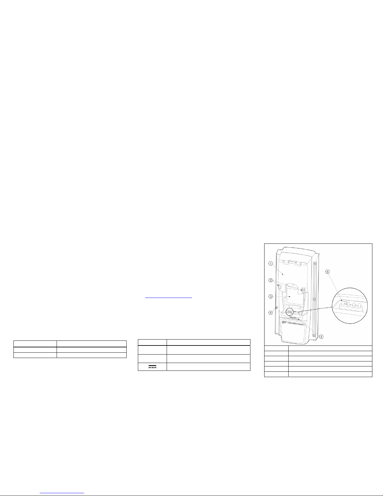
Parts of the GasAlertMicro Charger II
1 Charger module lid
2 Release tabs
3 Detector bay
4 Power port
5 Charger status LED
6 Battery connectors (contact pins)
Page 2
GasAlertMicro Charger II English Instruction Sheet
D5755/3 Page 2
Trimmed and folded dimensions: 4.125 (W) x 5.875 (H)
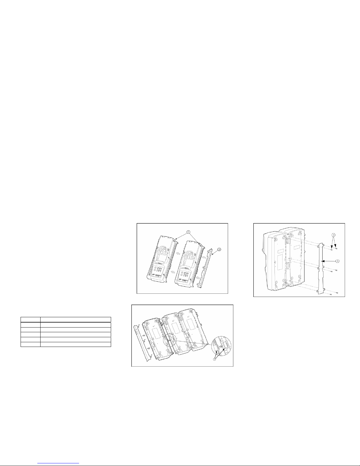
Adding Another Charger
a Warning
Maximum of six chargers can be connected together.
To add another charger, refer to Table 3, Figures 1, 2, and 3, and complete
the following procedures:
1. Deactivate the charger.
2. Remove the power cord from the POWER port.
3. Remove the end plate. There are three Phillips screws on the
front and three Philips screws on the back.
4. Attach the new charger. Ensure the charger connectors are
inserted correctly.
Note
Only one charger can be connected at a time.
5. When all of the chargers have been connected, attach the end
plate to the last charger using the Phillips screws.
6. A bottom cover plate must be attached to connect every two
chargers together to ensure stability of the units. Refer to Figure 3.
Use six Phillips flat-head screws for each bottom cover plate.
Table 3. Adding Another Charger
Item Description
1 Phillips pan-head screw
2 End plate
3 Charger connectors
4 Phillips flat-head screw
5 Bottom cover plate
Figure 1. Adding Another Charger (Top)
Figure 2. Adding Another Charger (Bottom)
Figure 3. Attaching the Bottom Cover Plate
Mounting the Charger
The charger can be easily mounted onto a secure surface. To mount the
charger, refer to Table 4, Figures 4 and 5, and complete the following
procedures:
1. Select a secure location for the charger to be mounted.
2. Using the screws provided, attach the wall mounting plates to the
charger. Refer to Figure 4 and Figure 5.
Note
When mounting two or more chargers, an individual wall
mounting plate is required for each charger that is mounted.
3. One Charger: When the plates are mounted, measure a distance
of 2.38 in. (60.32 mm) to install the retaining screws.
Multiple Chargers: If two or more chargers (that are attached
together) are being mounted, measure a distance of 1.64 in.
(41.70 mm) between each charger.
Page 3

GasAlertMicro Charger II English Instruction Sheet
D5755/3 Page 3
Trimmed and folded dimensions: 4.125 (W) x 5.875 (H)
Note
As there are a variety of surfaces that the charger can be
mounted to, retaining screws are not provided.
4. Use four retaining screws to attach the charger to the surface.
a Caution
Do not over torque the screws. Apply a maximum of 9 to 10
in-lbs torque.
Table 4. Mounting the Charger
Item Description
1
Foam spacer
2
Wall mounting plate
3
Grommet
4
Phillips self-tapping screw
Figure 4. Parts of the Wall Mounting Plate
Figure 5. Attaching the Wall Mounting Plate
Charging
aWarning
To charge successfully, the temperature must be between
50°F to 95°F (10°C to 35°C). If the detector emits a low battery
alarm, charge the battery immediately.
When charging a new battery for the first time, ensure that the battery pack
is fully charged before use (approximately 3.5 hours).
Table 5. Charger Status LED
Charger Status Description
Red Charging normally
Green Charge complete
Off
Charger or temperature fault,
battery pack not inserted, or power
is not applied to the charger
Note
When charging is complete, the detector can remain in the
charger without damage to the battery.
Charging the battery pack in temperatures above 86°F (30°C)
greatly reduces the life of the battery pack.
The battery pack may be hot immediately after charging.
A new battery pack requires approximately three charges to
achieve a full charge capacity.
Charging an extremely depleted battery, or charging more than
four units at one time, increases the time that is required to
charge.
When a fully charged battery is inserted into the docking bay, the
charger LED lights red for 6 to 10 minutes and then changes to
green. This will not damage the battery.
Charging the GA MicroBatt Rechargeable Battery Pack
To charge the GAMicroBatt rechargeable battery pack complete the
following procedures:
1. Insert the power cord into the charger port.
2. Plug the power cord into a Vac outlet. The charger LED lights red
then green as it performs a self-test. When the test is complete,
the LED deactivates.
Note
For mains plugs outside of North America, connect the universal
power adapter to the power cord.
3. Deactivate the detector.
4. Insert the detector into the docking bay bottom first. Ensure the
bottom of the detector is inserted correctly onto the contact pins.
Page 4

GasAlertMicro Charger II English Instruction Sheet
D5755/3 Page 4
Trimmed and folded dimensions: 4.125 (W) x 5.875 (H)
Figure 6. Inserting the Detector into the Charger
5. Close the charger lid and press until the release tabs click.
The charger emits a confirmation beep and the LED lights red to
indicate charging is in progress.
6. Allow the battery to charge fully (approximately 3.5-8 hours
depending upon the number of detectors being charged).
The LED changes to green when charging is complete.
When the detector is removed from the charger, the LED
deactivates.
Troubleshooting
If a problem occurs, refer to the following solutions. If the problem persists,
contact
BW Technologies by Honeywell.
Table 6. Troubleshooting Guide
Problem Possible Cause Solution
The detector is not
inserted correctly.
Firmly insert the detector in
the detector bay.
The charger
status LED does
not light when
the detector is
inserted.
Damaged or defective
battery pack.
Contact
BW Technologies
by Honeywell.
There is no
audible beep.
Internal damage to
battery or charger.
Contact BW Technologies
by Honeywell.
The battery is above
or below the operating
temperature.
Leave the detector in the
charger. When the battery
reaches room temperature,
charging will begin (approx.
1 hour).
Severely depleted
battery.
Contact BW Technologies
by Honeywell
.
There is an
audible beep,
but battery does
not charge.
Damaged or defective
battery pack.
Contact
BW Technologies
by Honeywell
.
Maintenance
a Warning
No user-serviceable parts inside.
To maintain the charger in good operating condition, perform the following
basic maintenance as required.
• Clean the exterior with a soft, damp cloth. Do not use solvents, soaps,
or polishes.
• Do not immerse the charger in liquids.
Battery Pack Storage
When stored for extended periods of time, ensure the battery is fully
charged and then recharged every 30 days.
Replacement Parts and Accessories
a Warning
To avoid personal injury or damage to the charger, use only
the specified replacement parts.
Table 7. Replacement Parts and Accessories
Model No. Description Qty
WMA-DOCK
Wall mounting kit Kit of 2
GAMIC-BAT-03
Rechargeable battery pack 1
D5755/3
Instruction sheet 1
DOCK-CPLATE-K
Bottom cover plate kit 1
GAMIC-V-CHRG3*
Vehicle charger adapter 1
*
Add suffix (-UK) for United Kingdom mains plug, (-EU) for European mains
plug, (-CH) for Switzerland mains plug, (-AU) for Australian mains plug.
Specifications
Size: 87.00 x 83.97 x 80.80 mm (3.4 x 3.3 x 3.2 in.)
Weight: 425.4 g (15 oz.)
Operating temperature: 10°C to 35°C (50°F to 95°F)
Humidity: 0 to 50%
Altitude: 2000 m (6561.66 ft.)
Power: 6 Vdc
, 1.0 A
Charger status LED: Color-coded LED advises the following: charging,
charging complete, and charger fault
Charge time: Typically 3.5 hours
Battery life: Typically 300 charges
Pollution degree: 2
Installation category: I
Certifications: Approved to both U.S. and Canadian standards for CSA
International for use in ordinary locations.
Page 5

GasAlertMicro Charger II English Instruction Sheet
D5755/3 Page 5
Trimmed and folded dimensions: 4.125 (W) x 5.875 (H)
This device complies with the FCC Part 15 and ICES-003 Canadian EMI
requirements. Operation is subject to the following two conditions:
1. This device may not cause harmful interference, and
2. this device must accept any interference received, including
interference that may cause undesired operation.
This equipment has been tested and found to comply with the limits for a
Class A digital device, pursuant to Part 15 of the FCC Rules and ICES-003
Canadian EMI requirements. These limits are designed to provide
reasonable protection against harmful interference when the equipment is
operated in a commercial environment.
This equipment generates, uses, and can radiate radio frequency energy
and, if not installed and used in accordance with the instruction manual,
may cause harmful interference to radio communications.
Operation of this equipment in a residential area is likely to cause harmful
interference in which case the user will be required to correct the
interference at his/her own expense.
a Warning
This product is designed for installation in an indoor location
only. All required National Electrical Codes and Safety
Standards must be followed.
Contacting BW Technologies by Honeywell
To contact BW Technologies by Honeywell call:
USA: 1-888-749-8878
Canada: 1-800-663-4164
Europe: +44 (0) 1295 700300
Other countries: +1-403-248-9226
Address correspondence to:
BW Technologies by Honeywell
2840 – 2
nd
Avenue S.E.
Calgary, AB
T2A 7X9
Email us at:
info@bwtnet.com
Visit BW Technologies by Honeywell’s web site at: www.gasmonitors.com
BW Technologies by
Honeywell
BW Technologies by
Honeywell
BW Technologies by
Honeywell
Corporate Headquarters America Europe
2840 - 2 Avenue S.E. 3279 West Pioneer Parkway 5 Canada Close
Calgary, AB Arlington, TX Banbury, Oxfordshire
Canada T2A 7X9 USA 76013 UK OX16 2RT
Warranty
LIMITED WARRANTY & LIMITATION OF LIABILITY
BW Technologies LP (BW) warrants this product to be free from defects in material and
workmanship under normal use and service for a period of two years, beginning on the date of
shipment to the buyer. This warranty extends only to the sale of new and unused products to the
original buyer. BW’s warranty obligation is limited, at BW’s option, to refund of the purchase
price, repair, or replacement of a defective product that is returned to a BW authorized service
center within the warranty period. In no event shall BW’s liability hereunder exceed the purchase
price actually paid by the buyer for the Product.
This warranty does not include:
a) fuses, disposable batteries or the routine replacement of parts due to the
normal wear and tear of the product arising from use;
b) any product which in BW’s opinion, has been misused, altered, neglected or
damaged by accident or abnormal conditions of operation, handling or use;
c) any damage or defects attributable to repair of the product by any person
other than an authorized dealer, or the installation of unapproved parts on
the product; or
The obligations set forth in this warranty are conditional on:
a) proper storage, installation, calibration, use, maintenance and compliance
with the product manual instructions and any other applicable
recommendations of BW;
b) the buyer promptly notifying BW of any defect and, if required, promptly
making the product available for correction. No goods shall be returned to
BW until receipt by the buyer of shipping instructions from BW; and
c) the right of BW to require that the buyer provide proof of purchase such as
the original invoice, bill of sale or packing slip to establish that the product is
within the warranty period.
THE BUYER AGREES THAT THIS WARRANTY IS THE BUYER’S SOLE AND EXCLUSIVE
REMEDY AND IS IN LIEU OF ALL OTHER WARRANTIES, EXPRESS OR IMPLIED,
INCLUDING BUT NOT LIMITED TO ANY IMPLIED WARRANTY OF MERCHANTABILITY OR
FITNESS FOR A PARTICULAR PURPOSE. BW SHALL NOT BE LIABLE FOR ANY SPECIAL,
INDIRECT, INCIDENTAL OR CONSEQUENTIAL DAMAGES OR LOSSES, INCLUDING LOSS
OF DATA, WHETHER ARISING FROM BREACH OF WARRANTY OR BASED ON
CONTRACT, TORT OR RELIANCE OR ANY OTHER THEORY.
Since some countries or states do not allow limitation of the term of an implied warranty, or
exclusion or limitation of incidental or consequential damages, the limitations and exclusions of
this warranty may not apply to every buyer. If any provision of this warranty is held invalid or
unenforceable by a court of competent jurisdiction, such holding will not affect the validity or
enforceability of any other provision.
 Loading...