

Page 1

IntelliDoX™
| Gas Detection
Docking Module
User Manual
50104991-168 EN-C5
Find Quality Products Online at: sales@GlobalTestSupply.com
www.GlobalTestSupply.com
Page 2

INTELLIDOX DOCKING MODULE USER MANUAL || ABOUT THIS PUBLICATION
Table of Contents
Table of Contents .............................................................................................................................. 1
About this Publication ................................................................................................................................... 3
Important Safety Information: Read First .................................................................................................... 4
Getting Started ............................................................................................................................................... 5
About the IntelliDoX Docking Module ................................................................................................ 6
What’s in the Box ............................................................................................................................... 7
IntelliDoX at a Glance ........................................................................................................................ 8
Inlet Keys ........................................................................................................................................... 9
LCD Screen ..................................................................................................................................... 11
Keypad ............................................................................................................................................. 12
Assemble Modules ....................................................................................................................................... 13
Work Plan: Assemble Individual Modules ........................................................................................ 14
Work Plan: Assemble Gangs of up to Five Connected Modules ...................................................... 15
Assemble the Stand ......................................................................................................................... 16
Connect Modules ............................................................................................................................. 17
Mount on a Wall ............................................................................................................................... 18
Mount on Parallel DIN Rails ............................................................................................................. 22
Prepare Modules for Use ............................................................................................................................. 25
Attach the End Plate ........................................................................................................................ 26
Connect the Exhaust Tubing ............................................................................................................ 27
Connect the Inlet filter ...................................................................................................................... 28
Insert the Inlet Plugs ........................................................................................................................ 29
Connect the Power .......................................................................................................................... 30
Connect the Module to a Network .................................................................................................... 31
Connect a Calibration Gas Cylinder ................................................................................................. 35
Dock Station Settings Menu ........................................................................................................................ 37
Display the Adjust Dock Station Settings Menu ............................................................................... 38
Adjust the LCD Brightness ............................................................................................................... 39
Adjust Date and Time Settings ........................................................................................................ 40
Configure Gas Inlets ........................................................................................................................ 41
Display the Select Language Menu ................................................................................................. 43
Display the About Summary Screen ................................................................................................ 44
Detector Operations ..................................................................................................................................... 45
Insert a Detector .............................................................................................................................. 46
Detector Operations Menu ............................................................................................................... 47
Bump Test ....................................................................................................................................... 48
FastBump ........................................................................................................................................ 50
Calibration ........................................................................................................................................ 52
Transfer Datalogs from a Detector ................................................................................................... 55
Display the Adjust Dock Station Settings Menu ............................................................................... 56
Charge a Detector ........................................................................................................................... 57
Configure Settings via Fleet Manager II Software ..................................................................................... 58
Protect Module Operations with a Passcode ................................................................................... 59
Configure Module and Detector Settings ......................................................................................... 60
Adjust Time and Date Settings via Fleet Manager II Software ......................................................... 64
Hibernation ................................................................................................................................................... 67
Configure Hibernation ...................................................................................................................... 68
Transfer Data Files ....................................................................................................................................... 73
Transfer Data Files from the Module ............................................................................................... 74
HONEYWELL PAGE 1 OF 117
Find Quality Products Online at: sales@GlobalTestSupply.com
www.GlobalTestSupply.com
Page 3

INTELLIDOX DOCKING MODULE USER MANUAL || ABOUT THIS PUBLICATION
Update Firmware .......................................................................................................................................... 76
Update Module Firmware ................................................................................................................. 77
Update Detector Firmware ............................................................................................................... 80
Replace Detector Cradle and Calibration Insert ........................................................................................ 83
Replace the Detector Cradle ............................................................................................................ 85
Replace the Calibration Insert .......................................................................................................... 87
Maintenance ................................................................................................................................................. 89
Clean and Maintain the Module ....................................................................................................... 90
Calibration Equipment and Gases ................................................................................................... 91
Technical Specification and Warranty ....................................................................................................... 92
Technical Specification .................................................................................................................... 93
Limited Warranty and Limitation Liability .......................................................................................... 95
Troubleshooting ........................................................................................................................................... 96
Compliance Tests ............................................................................................................................ 97
Detectors ......................................................................................................................................... 99
Modules ......................................................................................................................................... 100
Network Connections ..................................................................................................................... 103
Calibration of PID Sensor .............................................................................................................. 104
Safety Suite Device Configurator Software ............................................................................................. 105
Connect an IntelliDoX to the Safety Suite Device Configurator ..................................................... 106
Adjust the Time and Date .............................................................................................................. 107
Set the Time Zone ......................................................................................................................... 108
Transfer data files .......................................................................................................................... 109
Download data from a file .............................................................................................................. 110
Update the Firmware ..................................................................................................................... 111
Glossary ...................................................................................................................................................... 114
Contact us .................................................................................................................................................. 117
HONEYWELL PAGE 2 OF 117
Find Quality Products Online at: sales@GlobalTestSupply.com
www.GlobalTestSupply.com
Page 4

INTELLIDOX DOCKING MODULE USER MANUAL || ABOUT THIS PUBLICATION
About this Publication
IntelliDoX® Docking ModuleOperator Manual
50104991-168 || OM-EN-FMSU-C1
© 2015-2018 Honeywell. All rights reserved.
The IntelliDoX Docking Module is designed to support multiple detectors manufactured by
Honeywell. As a result, certain procedures, features and options described in this manual
may not be supported by most of the compatible detector models. To understand which
procedures, features and options are supported, refer to the appropriate detector operator
manual.
Ensure that you are familiar with the use of personal gas detection devices and
accessories, and take appropriate action in the event of an alarm condition.
While this information is presented in good faith and believed to be accurate, Honeywell
disclaims the implied warranties of merchantability and fitness for a particular purpose and
makes no express warranties except as may be expressly stated in its written agreement
with and for its customers. In no event is Honeywell liable to anyone for any indirect,
special or consequential damages. The information and specifications in this document
are subject to change without notice.
Trademarks
Brand or product names are trademarks of their respective owners. The following brand or
product names are trademarks of Honeywell:
• Fleet Manager II
• IntelliDoX
Signal Words
This manual uses the following signal words, as defined by ANSI Z535.4-1998:
Hazardous situation which, if not avoided, will result in death or serious injury. This
symbol identifies the most extreme hazardous situations.
Hazardous situation which, if not avoided, could result in death or serious injury.
Hazardous situation which, if not avoided, may result in moderate or minor injury.
Situations which, if not avoided, may result in property damage.
HONEYWELL PAGE 3 OF 117
Find Quality Products Online at: sales@GlobalTestSupply.com
www.GlobalTestSupply.com
Page 5

INTELLIDOX DOCKING MODULE USER MANUAL || IMPORTANT SAFETY INFORMATION: READ FIRST
Important Safety Information: Read First
To ensure personal safety, read all Safety
Information and Warnings before using this
equipment.
Use this equipment only as specified by the
manufacturer. Failure to do so may impair
protection provided by the equipment.
The safety and security of any system or network
incorporating this equipment and its accessory
components is the responsibility of the assembler
of the system.
Follow all required National Electric Codes (NEC)
and safety standards.
This IntelliDoX module is intended for use as a
stand-alone docking module, or as a component
in a connected gang of up to five IntelliDoX
modules.
If the equipment is damaged or parts are missing,
contact Honeywell immediately.
Substitution of components may impair the safety
of the equipment.
Do not attempt to disassemble, adjust, or service
the equipment unless instructions are provided to
perform a procedure, or a component is listed as
a user-replaceable component in the user
manual. Use only Honeywell replacement
components.
To eliminate the risk of electrical shock,
disconnect the equipment when cleaning or
performing maintenance.
This equipment uses potentially harmful gas for
calibrations. The equipment must be attached to
a venting system or be used in a well-ventilated
area.
To prevent gas leaks, the end plate must be
attached and locked with the latch arm lock
before connecting power supply and/or
connecting gas cylinders. The end plate must
remain securely latched at all times during
operation.
Perform calibrations and bump tests only in a
normal atmosphere (20.9% v/v O
hazardous gas.
) that is free of
2
The maximum recommended calibration tubing
length is 10 meters (33 feet). Use of tubing that is
longer than the recommended length may result
in inaccurate or failed compliance tests or
calibrations.
The maximum recommended exhaust tubing
length is 15 meters (49.5 feet).
Ensure that the inlet filter is clean.
The use of calibration gas cylinders other than
those specified by Honeywell may result in
unsafe calibration or possible non-recoverable
failure of the equipment, and will invalidate the
warranty.
Do not use calibration gas cylinders past their
expiration date.
Ensure that all calibration gas cylinders are in
good condition.
Ensure that all calibration gas cylinders contain
enough gas.
Ensure the exhaust line is not connected to a
negative pressure system.
A demand flow regulator must be used with all
calibration gas cylinder connections. The module
inlet should not be pressurized.
Failed tests can result if inlets are not set up
correctly.
Do not expose the equipment to electrical shock
or severe and/or continuous mechanical shock.
Do not immerse the equipment in liquids.
Products may contain materials that are
regulated for transportation under domestic and
international dangerous goods regulations.
Return product in compliance with appropriate
dangerous goods regulations. Contact freight
carrier for further instructions.
To prevent the corruption or loss of data and/or
software and/or firmware, do not deactivate the
equipment while performing datalog transfers,
bump tests, calibrations or other operations.
HONEYWELL PAGE 4 OF 117
Find Quality Products Online at: sales@GlobalTestSupply.com
www.GlobalTestSupply.com
Page 6

INTELLIDOX DOCKING MODULE USER MANUAL || GETTING STARTED
Getting Started
This section contains information and illustrations related to the module and its
components. It also includes an overview of the module settings menu and general
instructions for inserting a detector and using the detector operations menu on the
module.
HONEYWELL PAGE 5 OF 117
Find Quality Products Online at: sales@GlobalTestSupply.com
www.GlobalTestSupply.com
Page 7

INTELLIDOX DOCKING MODULE USER MANUAL || GETTING STARTED
About the IntelliDoX Docking Module
The IntelliDoX Docking Module (‘the module’) is an automatic test and calibration station
for use with portable gas detectors manufactured by Honeywell. The module automatically
performs essential procedures including sensor identification, bump tests, calibrations,
alarm tests and data transfers. It also retains a cumulative record of detector datalogs and
event logs that are transferred to and stored in onboard memory.
Modules may be used as individual, stand-alone docking stations. They may also be
connected to form gangs of up to 5 modules that function independently. Connected
modules share power, network and gas connections.
Modules may be connected to a network via an Ethernet cable for enhanced access to
and control of administrative and maintenance tasks. Modules are compatible with Fleet
Manager II software, version 4.0 or higher.
Normal Operating Conditions
The module is designed to be safe in the following conditions:
Indoor use only;
Normal atmosphere (20.9% v/v O
Temperature range of +50°F to +95°F (+10°C to +35°C) ; and
Relative humidity of 10% to 90% non-condensing.
If the intended operating environment does not match these criteria, Honeywell
recommends that you consult a qualified professional specialist prior to installing and
using any modules.
This equipment uses potentially harmful gas for calibrations. The module must be
attached to a venting system or be used in a well-ventilated area.
) that is free of hazardous gas;
2
Parts and Accessories
Replaceable parts are sold separately. To receive a complete list of replaceable parts
approved for use with this product, contact Honeywell or an authorized distributor, or visit
Gas detectors, calibration and purge gas cylinders, and other accessories are sold
separately. To receive a complete list of calibration gases and accessories approved for
use with this product, contact Honeywell or an authorized distributor, or visit the product
HONEYWELL PAGE 6 OF 117
Find Quality Products Online at: sales@GlobalTestSupply.com
www.GlobalTestSupply.com
Page 8

INTELLIDOX DOCKING MODULE USER MANUAL || GETTING STARTED
What’s in the Box
IntelliDoX Docking Module
Each IntelliDoX Docking Module package contains:
1. One module with a factory-installed nest for a compatible portable gas detector, a
single-inlet key, and an attached end plate;
NOTE: If the end plate is not attached to the IntelliDoX docking module or is
missing, contact Honeywell or an authorized distributor immediately.
One printed Quick Reference Guide;
One CD containing the module Operator Manual and Quick Reference Guide in PDF
format; and
One CD containing Fleet Manager II software, v4.0 or higher.
The power supply and power cord, Ethernet cable, tubing, inlet filters and plugs, quick
connect fittings, and miscellaneous other fittings are packaged separately as the
IntelliDoX Enabler Kit. One Enabler Kit is required for each individual module or gang of
up to 5 connected modules.
If the module is damaged or if parts are missing, contact Honeywell or an authorized
distributor immediately.
IntelliDoX Enabler Kit
You need one IntelliDoX Enabler Kit for each stand-alone IntelliDoX module or gang of up
to 5 connected modules. Each Enabler Kit contains:
1. One power supply and AC power cord appropriate to shipping destination;
One ethernet cable;
Gas tubing, 1/8 inch I.D., 4.6 meters (15 feet);
Quick connect fittings;
Inlet filters and plugs;
Connectors with attached 3/16 inch I.D. tubing for use with demand flow regulators;
Miscellaneous connectors;
One CD containing the IntelliDoX operator manual and the quick reference guide in
PDF format; and
One CD containing Fleet Manager II software, v4.0 or higher.
If Enabler Kit parts are damaged or missing, or if additional Enabler Kits are required,
contact Honeywell or an authorized distributor immediately.
Fleet Manager II Software
Fleet Manager II is proprietary instrument management software developed by Honeywell.
You can use Fleet Manager II to:
• Configure and manage compatible docking modules and detectors;
• Update firmware for compatible docking modules and detectors;
• Configure and manage compliance tests;
• Import, manage and analyze datalogs, event logs and compliance test results; and
• Automate certain procedures and processes for compatible docking modules and
detectors.
To learn more about instrument management via Fleet Manager II software, refer to the
Fleet Manager II Operator Manual or visit the product website at
HONEYWELL PAGE 7 OF 117
Find Quality Products Online at: sales@GlobalTestSupply.com
www.GlobalTestSupply.com
Page 9

INTELLIDOX DOCKING MODULE USER MANUAL || GETTING STARTED
IntelliDoX at a Glance
HONEYWELL PAGE 8 OF 117
Find Quality Products Online at: sales@GlobalTestSupply.com
www.GlobalTestSupply.com
Page 10

INTELLIDOX DOCKING MODULE USER MANUAL || GETTING STARTED
Single-inlet key: IntelliDoX
activates gas inlet 1 and
Inlet Keys
By default, IntelliDoX is configured to connect one calibration gas cylinder to gas inlet 1.
In this configuration,
calibration gas cylinder to IntelliDoX, you must insert a multi-inlet key to activate
inlets 1, 2
Single-inlet Key
, 3, and 4.
gas inlets 2, 3, and 4 are inactive. To connect more than one
gas
Insert the single-inlet key when only one gas inlet is required to support compliance test
operations performed on the module.
When the single-inlet key is inserted into a module, gas inlet 1 is active and gas inlets 2, 3
and 4 are inactive.
Gas Cylinder with a Single-Inlet Key
When you connect a gas cylinder to IntelliDoX with a single-inlet key, you will see one
connected gas type on the LCD screen:
HONEYWELL PAGE 9 OF 117
Find Quality Products Online at: sales@GlobalTestSupply.com
www.GlobalTestSupply.com
Page 11

INTELLIDOX DOCKING MODULE USER MANUAL || GETTING STARTED
Multi-inlet key: IntelliDoX
Multi-inlet key: IntelliDoX
activates gas inlets 1, 2, 3,
Multi-inlet Key
Insert the multi-inlet key when more than one gas inlet is required to support compliance
test operations performed on the module.
When a multi-inlet key is inserted into a module, gas inlets 1, 2 3 and 4 are active.
Connected Gas Cylinders with a Multi-Inlet Key
When you connect multiple gas cylinders to IntelliDoX with a multi-inlet key, you will see
multiple connected gas types on the LCD screen:
Change an Inlet Key
To remove the inlet key, pinch the release tabs together, and then pull the inlet key out.
To insert the inlet key, align the inlet key with the opening and push firmly.
an inlet key.
1. Disconnect the power cord from the IntelliDoX.
On the inserted inlet key, press the release tabs and pull to remove the inlet key.
Insert the new inlet key into the IntelliDoX.
Connect the power cord to the IntelliDoX.
activates gas inlets 1, 2,
Always disconnect the power cord from the IntelliDoX before you change
Find Quality Products Online at: sales@GlobalTestSupply.com
HONEYWELL PAGE 10 OF 117
www.GlobalTestSupply.com
Page 12

INTELLIDOX DOCKING MODULE USER MANUAL || GETTING STARTED
LCD Screen
Screen Color
HONEYWELL PAGE 11 OF 117
Find Quality Products Online at: sales@GlobalTestSupply.com
www.GlobalTestSupply.com
Page 13
INTELLIDOX DOCKING MODULE USER MANUAL || GETTING STARTED
Keypad
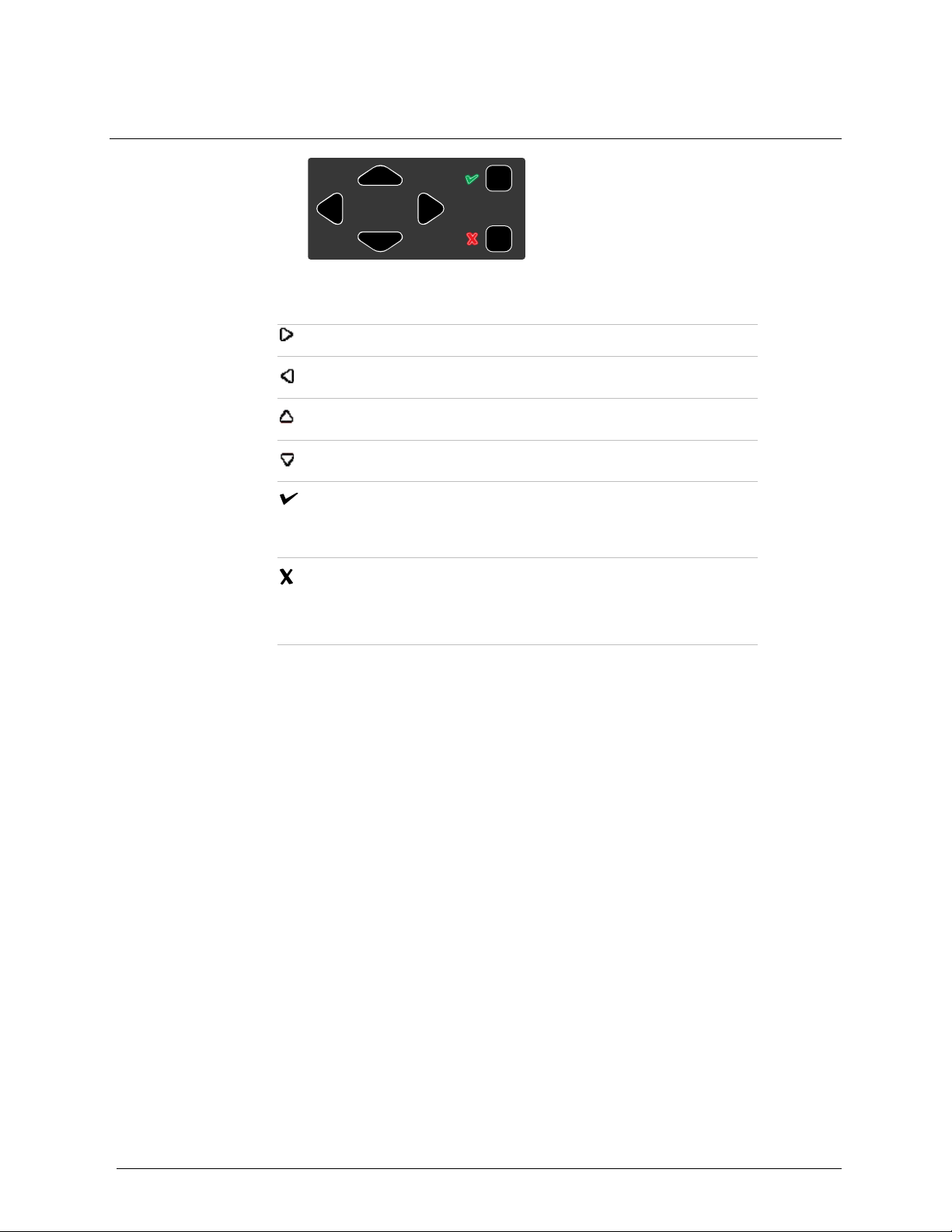
Keypad Buttons
Scroll right
Scroll left
Scroll up
Scroll down
Press and hold until the module settings menu is displayed.
Press and release to select a menu item or save changes.
Press and hold until an operation is cancelled.
Press and release to close a menu item or return to a previous
screen or cancel changes.
HONEYWELL PAGE 12 OF 117
Find Quality Products Online at: sales@GlobalTestSupply.com
www.GlobalTestSupply.com
Page 14

INTELLIDOX DOCKING MODULE USER MANUAL || ASSEMBLE MODULES
Assemble Modules
This section contains work plans and instructions for assembling and installing
individual modules and gangs of up to five modules.
HONEYWELL PAGE 13 OF 117
Find Quality Products Online at: sales@GlobalTestSupply.com
www.GlobalTestSupply.com
Page 15

INTELLIDOX DOCKING MODULE USER MANUAL || ASSEMBLE MODULES
Work Plan: Assemble Individual Modules
Follow these steps to assemble and prepare an individual module for first-time use:
1. Place the module and component parts on a clean, dry work surface.
Verify that the appropriate inlet key is inserted. Replace the inlet key if necessary. For
more information, see Inlet Keys on page 9.
Assemble the stand, or mount the module on a wall or DIN rail. For more information see:
a. Assemble the Stand on page 16
b. Mount on a Wall on page 18.
c. Mount on Parallel DIN Rails on page 22.
Prepare the module for use. For more information, see Prepare Modules for Use on
page 25.
a. Attach the end plate. For more information, see Attach the End Plate on
page 26.
b. Connect an inlet filter to the purge inlet. For more information, see Connect
the Inlet filter on page 28.
c. Insert an inlet plug into each unused inlet. For more information, see Insert
the Inlet Plugs on page 29.
d. Connect the exhaust tubing. For more information, see Connect the
Exhaust Tubing on page 27.
e. Connect the power. For more information, see Connect the Power on page
30.
f. Connect to a network. See Connect the Module to a Network on page 31.
Connect the calibration gas cylinder or cylinders, and then configure the gas inlets. For
more information, see Configure Gas Inlets on page 41.
HONEYWELL PAGE 14 OF 117
Find Quality Products Online at: sales@GlobalTestSupply.com
www.GlobalTestSupply.com
Page 16
INTELLIDOX DOCKING MODULE USER MANUAL || ASSEMBLE MODULES
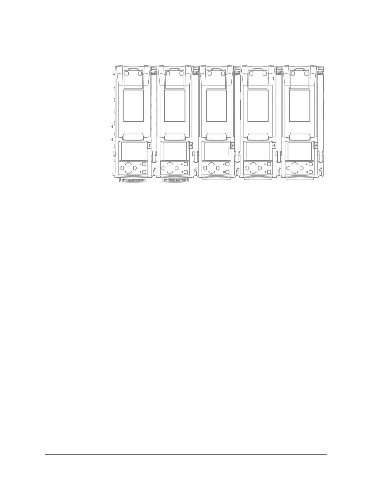
Work Plan: Assemble Gangs of up to Five Connected Modules
Up to five modules may be connected to form a gang. Connected modules share the
power supply, exhaust tubing, inlet filter, connected test gas cylinders and network
connection. Follow these steps to assemble and prepare gangs of up to five connected
modules for first use:
1. Place the modules and component parts on a clean, dry work surface.
Verify that the appropriate inlet keys are inserted. Replace the inlet keys if necessary. For
more information, see Inlet Keys on page 9.
Assemble the stand or mount the module on a wall or DIN rail if necessary. For more
information, see:
• Assemble the Stand on page 16.
• Mount on a Wall on page 18.
• Mount on Parallel DIN Rails on page 22.
Connect up to 5 modules. For more information, see:
• Connecting Modules on page 17.
• Mounting Connected Modules on a Wall on page 20.
Prepare the connected modules for use. For more information, see Prepare Modules for
Use on page 25.
a. Attach the end plate to the last module in the gang. See Attach the End Plate on
page 26.
b. Connect an inlet filter to the purge inlet on the first module in the gang. For more
information, see Connect the Inlet filter on page 28.
c. Insert an inlet plug into each unused inlet on the first module in the gang. For
more information, see Insert the Inlet Plugs on page 29.
d. Connect the exhaust tubing to the first module in the gang. For more information,
see Connect the Exhaust Tubing on page 27.
e. Connect the power to the first module in the gang.
f. Connect to a network. See Connect the Module to a Network on page 31.
Connect the calibration gas cylinder or cylinders, and then configure the gas inlets. For
more information, see Connect a Calibration Gas Cylinder on page 35 and Configure
Gas Inlets on page 41.
HONEYWELL PAGE 15 OF 117
Find Quality Products Online at: sales@GlobalTestSupply.com
www.GlobalTestSupply.com
Page 17

INTELLIDOX DOCKING MODULE USER MANUAL || ASSEMBLE MODULES
Assemble the Stand
The back panel of the module can be used as a stand to support an individual module or
gang of up to five connected modules at an angle that is suitable for normal use.
Do not use the stand if parts are missing or damaged. Do not attempt to repair or
replace any parts of the stand. If the plate is damaged or missing, contact Honeywell
or an authorized distributor.
The equipment must be used only in a normal atmosphere (20.9% v/v O2) that is free
of hazardous gas. Do not use the equipment in a hazardous area. Failure to adhere
to this caution can lead to fire and/or explosion.
Do not install near heat sources or on vibrating surfaces.
The equipment is intended for indoor use only.
Assembling the Stand
1. Disconnect the power cord, network cable, tubing and inlet filter assemblies.
Detach the back panel.
a. Hold the module with the back panel facing toward you.
b. Find the panel latch at the top left side of the module, near the panel hinge.
c. Press down firmly on the panel latch, and then continue to press down while
Pinch the arms of the metal brace together to release the ends. If the metal brace is
damaged or missing, contact Honeywell or an authorized distributor.
Attach the back panel at the hinged joint. Align the hinges on the module with the hinge
pins on the back panel. Firmly push the back panel to the left to lock the hinge pins into
place.
Pinch the arms of the metal brace together and insert into the brace receptacle on the
back of the module.
Prepare the module for use.
a. Attach the end plate. Verify that the latch arm is lowered and locked.
b. Connect the inlet filters, tubing, network connection and power cord.
you slide the panel to the right until the hinge pins are detached.
HONEYWELL PAGE 16 OF 117
Find Quality Products Online at: sales@GlobalTestSupply.com
www.GlobalTestSupply.com
Page 18

INTELLIDOX DOCKING MODULE USER MANUAL || ASSEMBLE MODULES
Connect Modules
Up to 5 modules may be connected to form a gang. Connected modules share a power
supply, network connection, exhaust tubing, inlet filter assemblies, and connected
calibration gas cylinders.
Connecting Modules
1. Assemble the stand for each module you plan to connect. For more information, see
Assemble the Stand on page 16.
Connect two modules.
a. Unlock and raise the latch arm on the first module. If an end plate is
attached, remove it.
b. Align the connection port, outlets and stand on the first module with the
connection port, inlets and stand on the second module.
c. Push the modules firmly together to connect. Verify that the stands are
connected, and then lower and lock the latch arm on the first module.
2. Unlock and raise the latch arm on the last connected module, and then connect
another module. Repeat as necessary to connect up to a maximum of five modules in
one gang.
3. Prepare connected modules for use.
a. Verify that connected modules are firmly attached and latch arms are lowered
and locked.
b. Attach the end plate to the last module in the gang. Verify that the latch arm is
lowered and locked.
c. Connect the inlet filters, tubing, network connection and power cord.
d. Verify that each module in the gang is activated and a consecutive bay number is
displayed on the LCD. See LCD Screen on page 11.
Disconnecting Modules
1. Disconnect the power.
a. Unlock and raise the latch arm between two modules.
b. Holding one unit in each hand, gently pull the modules apart.
c. Repeat as necessary until all modules in the gang are disconnected.
HONEYWELL PAGE 17 OF 117
Find Quality Products Online at: sales@GlobalTestSupply.com
www.GlobalTestSupply.com
Page 19

INTELLIDOX DOCKING MODULE USER MANUAL || ASSEMBLE MODULES
Mount on a Wall
You can use the back panel to mount the module securely to a wall. Because wall
materials vary, mounting hardware is not provided. Honeywell strongly recommends that
wall-mounting is performed by a qualified installation contractor. Sufficient expertise is
required to:
1. Determine the strength of the wall supporting the module; and
Select mounting hardware appropriate to the weight and normal use of the module.
Before you Begin
1. Select a suitable installation location. Each module or gang of connected modules
requires:
• Access to an appropriate power source.
• Access to a network connection, if using.
• Access to calibration gas sources.
• Adequate clearance for the power cord, cables and tubing.
• Adequate clearance for normal use, maintenance and cleaning.
Have ready appropriate mounting hardware. Each module requires sufficient hardware for
4 anchor points.
Have ready tools and accessories required to install the mounting hardware.
Incomplete or improper mounting may result in property damage and/or personal
injury.
Do not install near heat sources or on vibrating surfaces.
The wall and the mounting hardware must be strong enough to support the
equipment during normal use.
The equipment must be used only in a normal atmosphere (20.9% v/v O
of hazardous gas. Do not use the equipment in a hazardous area. Failure to adhere
to this caution can lead to fire and/or explosion.
The equipment is intended for indoor use only.
This equipment uses potentially harmful gas for calibrations. The equipment must be
attached to a venting system or be used in a well-ventilated area.
) that is free
2
HONEYWELL PAGE 18 OF 117
Find Quality Products Online at: sales@GlobalTestSupply.com
www.GlobalTestSupply.com
Page 20

INTELLIDOX DOCKING MODULE USER MANUAL || ASSEMBLE MODULES
Mounting Individual Modules on a Wall
1. Prepare the modules for mounting.
a. Disconnect modules that are connected into gangs.
b. Disconnect the power cord, network cable, tubing and inlet filter
assemblies.
c. Remove the end plate.
2. Detach the back panel.
a. Hold the module with the back panel facing toward you.
b. Find the panel latch at the top left side of the module, near the panel hinge.
c. Press down firmly on the panel latch, and then continue to press down while
you slide the panel to the right until the hinge pins are detached.
3. Mark the position of the anchor points on the wall, and then drill the holes.
a. Hold the panel against the wall in the desired position.
b. Use a pencil or non-permanent marker to mark the center of the 4 anchor
points, and then set the back panel aside.
c. Drill through the center of each anchor point mark.
4. Secure the panel to the wall with the metal brace facing out. Use appropriate
hardware for each of the 4 anchor points. Do not overtighten.
Attach the module to the mounted back panel.
a. Align the hinges and hook receptacles on the module with the hinge pins
and hooks on the mounted panel.
b. When the module lies flat against the mounted panel, push it firmly to the
left to lock it onto the panel.
5. Prepare the module for use. For more information, see Prepare Modules for Use on
page 25.
a. Attach the end plate. Verify that the latch arm is lowered and locked.
b. Connect the inlet filters, tubing, network connection and power cord.
Removing an Individual Module from a Mounted Back Panel
1. Disconnect the power cord, network cable, tubing and inlet filter assemblies.
2. Find the panel latch at the top right side of the module, near the panel hinge.
3. Press down firmly on the panel latch, and then continue to press down while you push
the module to the right until the hinge pins and hooks are detached. Remove the
module.
HONEYWELL PAGE 19 OF 117
Find Quality Products Online at: sales@GlobalTestSupply.com
www.GlobalTestSupply.com
Page 21

INTELLIDOX DOCKING MODULE USER MANUAL || ASSEMBLE MODULES
Mounting Connected Modules on a Wall
1. Prepare the modules for mounting.
c. Disconnect modules that are connected into gangs.
d. Disconnect the power cord, network cable, tubing and inlet filter
assemblies.
e. Remove the end plate.
2. Detach the back panel from the modules.
a. Hold the module with the back panel facing toward you.
b. Find the panel latch at the top left side of the module, near the panel hinge
c. Press down firmly on the panel latch, and then continue to press down while
you slide the panel to the right until the hinge pins are detached.
3. Mark the position of the anchor points, and drill holes for the first panel.
a. Hold the panel against the wall in the desired position.
b. Use a pencil or non-permanent marker to mark the center of the 4 anchor
points, and then set the back panel aside.
4. Drill through the center of each anchor point mark.
Secure the first panel to the wall with the metal brace facing out. Use appropriate
hardware for each of the 4 anchor points. Do not overtighten.
Clip the second panel to the first panel, and then secure it to the wall. Use
appropriate hardware for each of the 4 anchor points. Do not overtighten. Repeat
as necessary to mount up to 5 connected panels.
5. Attach a module to the first panel.
a. Align the hinges on the module with the hinge pins on the mounted panel.
Align the hooks on the mounted panel with the hook receptacles on the
module.
b. When the module lies flat against the mounted panel, firmly push to the left
to lock onto the panel. If this is difficult, loosen the mounting hardware
slightly and try again.
6. Attach a module to the second panel and connect it to the first module.
a. Unlock and raise the latch arm on the first module.
b. Align the hinges on the next module with the hinge pins on the next
mounted panel. Align the hooks on the next mounted panel with the hook
receptacles on the next module. Align the connections on the modules.
c. When the next module lies flat against the next mounted panel, firmly push
to the left to lock it onto the panel and ensure a full connection with the first
module.
d. Lower and lock the latch arm. Repeat as necessary to attach and connect
up to 5 modules.
7. Prepare connected modules for use.
f. Verify that connected modules are firmly attached and latch arms are
lowered and locked.
g. Attach the end plate to the last module in the gang. Verify that the latch
arm is lowered and locked.
h. Connect the inlet filters, tubing, network connection and power cord.
i. Verify that each module in the gang is activated and a consecutive bay
number is displayed on the LCD. See LCD Screen on page 11.
HONEYWELL PAGE 20 OF 117
Find Quality Products Online at: sales@GlobalTestSupply.com
www.GlobalTestSupply.com
Page 22

INTELLIDOX DOCKING MODULE USER MANUAL || ASSEMBLE MODULES
Removing Connected Modules from Mounted Back Panels
1. Disconnect the power cord, network cable, tubing and inlet filter assemblies.
2. Unlock and lift the latch arm between the two modules at the end of the gang.
3. Find the panel latch at the top right side of the module at the end of the gang.
4. Press down firmly on the panel latch, and then continue to press down while you push
the module to the right until the hinge pins and hooks are detached. For best results,
Honeywell recommends that you hold the remainder of the gang firmly in position
while pushing to help protect the remaining modules in the gang from excessive
movement or falls.
5. Repeat steps 2, 3 and 4 until only one module remains.
6. Repeat steps 3 and 4 to remove the final module.
HONEYWELL PAGE 21 OF 117
Find Quality Products Online at: sales@GlobalTestSupply.com
www.GlobalTestSupply.com
Page 23

INTELLIDOX DOCKING MODULE USER MANUAL || ASSEMBLE MODULES
Mount on Parallel DIN Rails
The module is designed for installation on two parallel top hat DIN rails that are 35
millimeters by 7.5 millimeters, as per EN Standard 50022. Honeywell strongly
recommends that mounting is performed by a qualified installation contractor. Sufficient
expertise is required to:
1. Determine the strength of the wall supporting the module; and
2. Select DIN rails and mounting hardware appropriate to the weight and normal use of
the total number of mounted modules.
What is a DIN Rail?
A DIN rail is a metal strip that is used to mount industrial equipment. DIN rail can be cut to
suit specific applications. Multiple rows of DIN rail can be used. The module is designed
for installation on two parallel top hat DIN rails that are 35 millimeters by 7.5 millimeters,
as per EN Standard 50022.
Before You Begin
1. Select a suitable installation location. Each module or gang of connected modules
requires:
Install two parallel top hat DIN rails that are 35 millimeters by 7.5 millimeters. Use
DIN rails that are appropriate for the combined weight and normal use of the total number
of mounted modules. Space the DIN rails 15.2 centimeters (6 inches) apart on center.
Honeywell strongly recommends using a DIN rail end plate when mounting in a vehicle, or
when lateral motion is possible, or when attaching the first module in a ganged system. If
a DIN rail end plate is not available, use the anchor holes in the back panel to secure the
module to the wall.
Incomplete or improper mounting may result in property damage and/or personal
injury.
Do not install near heat sources or on vibrating surfaces.
The wall and the mounting hardware must be strong enough to support the
equipment during normal use.
The equipment must be used only in a normal atmosphere (20.9% v/v O
of hazardous gas. Do not use the equipment in a hazardous area. Failure to adhere
to this caution can lead to fire and/or explosion.
The equipment is intended for indoor use only.
• Access to an appropriate power source.
• Access to a network connection, if using.
• Access to calibration gas sources.
• Adequate clearance for the power cord, cables and tubing.
• Adequate clearance for normal use, maintenance and cleaning.
) that is free
2
HONEYWELL PAGE 22 OF 117
Find Quality Products Online at: sales@GlobalTestSupply.com
www.GlobalTestSupply.com
Page 24

INTELLIDOX DOCKING MODULE USER MANUAL || ASSEMBLE MODULES
Mounting Modules on Parallel DIN Rails
1. Prepare the modules for mounting.
a. Disconnect modules that are connected into gangs.
b. Disconnect the power cord, network cable, tubing and inlet filter
assemblies.
c. Remove the end plate.
2. Attach a module to the DIN rails. Repeat as necessary until all modules attached.
a. Hold the module upright with the back panel toward the DIN rails. Place the
top DIN mount over the top of the upper DIN rail and then lower the module
toward the lower DIN rail until it snaps into place.
b. Verify that the module is firmly attached to both the upper DIN rail and the
lower DIN rail.
3. Connect the attached modules into gangs of up to 5, if using. Repeat as necessary
until all gangs are connected.
a. Snap the first module into position on the DIN rail, and then unlock and
raise the latch arm.
b. Snap the second module onto the DIN rail, and then slide it into position
beside the first module. Push the modules firmly together and then lower
and lock the latch arm.
c. Repeat as necessary until the gang is complete.
4. Prepare the module for use. For more information, see Prepare Modules for Use on
page 25.
a. Attach the end plate. Verify that the latch arm is lowered and locked.
b. Connect the inlet filters, tubing, network connection and power cord.
HONEYWELL PAGE 23 OF 117
Find Quality Products Online at: sales@GlobalTestSupply.com
www.GlobalTestSupply.com
Page 25

INTELLIDOX DOCKING MODULE USER MANUAL || ASSEMBLE MODULES
Removing an Individual Module from Parallel DIN Rails
1. Disconnect the power cord, network cable, tubing and inlet filter assemblies.
Remove the end plate.
Find the DIN mount lock on the lower right side of the module.
Hold the DIN mount lock down, and then tilt the module away from the lower DIN rail until
the lower DIN mount is released. Release the DIN mount lock and remove the module
from the upper DIN rail.
Removing Connected Modules from Parallel DIN Rails
1. Disconnect the power cord, network cable, tubing and inlet filter assemblies.
Remove the end plate.
Lift the latch arm between connected modules at the end of the gang.
Find the DIN mount lock on the lower right side of the last module. Hold the DIN mount
lock down, and then slide the module along the DIN rails until it is separated from the
gang.
Hold the DIN mount lock down, and then tilt the module away from the lower DIN rail until
the lower DIN mount is released. Release the DIN mount lock and remove the module
from the upper DIN rail.
Repeat steps 3, 4 and 5 until only one module remains.
Repeat steps 3 and 4 to remove the final module.
HONEYWELL PAGE 24 OF 117
Find Quality Products Online at: sales@GlobalTestSupply.com
www.GlobalTestSupply.com
Page 26

INTELLIDOX DOCKING MODULE USER MANUAL || PREPARE MODULES FOR USE
Prepare Modules for Use
This section contains instructions and information related to preparing modules for use.
The following topics are included.
HONEYWELL PAGE 25 OF 117
Find Quality Products Online at: sales@GlobalTestSupply.com
www.GlobalTestSupply.com
Page 27

INTELLIDOX DOCKING MODULE USER MANUAL || PREPARE MODULES FOR USE
Attach the End Plate
The end plate must be attached and locked with the latch arm before connecting power
supply or connecting gas cylinders. The end plate must remain securely latched at all
times during operation. If the end plate is detached during operation, disconnect power
and replace the end plate immediately. Abnormal performance may occur when the end
plate is detached or removed.
Failure to comply may result in incorrect or failed compliance tests or calibrations.
Attaching the End Plate
1. Unlock and raise the latch arm.
2. Attach the end plate. Verify that the end plate is firmly attached and set flush with the
edge of the module.
3. Lower and lock the latch arm.
Removing the End Plate
1. Unlock and raise the latch arm.
Remove the end plate.
HONEYWELL PAGE 26 OF 117
Find Quality Products Online at: sales@GlobalTestSupply.com
www.GlobalTestSupply.com
Page 28

INTELLIDOX DOCKING MODULE USER MANUAL || PREPARE MODULES FOR USE
Connect the Exhaust Tubing
Each IntelliDoX Enabler Kit includes tubing that may be cut to a length that is appropriate
for the exhaust inlet.
The maximum recommended exhaust tubing length is 15 meters (49.5 feet).
Ensure the exhaust line is not connected to a negative pressure system.
Connecting the Exhaust Tubing
1. Inspect the tubing to ensure that it is free of obstructions and defects.
Cut tubing to a length that is appropriate for exhaust, and then attach a male quick
connect fitting to one end.
Connect the exhaust tubing to the exhaust outlet using the quick connect fitting.
Verify that the exhaust tubing is not connected to a negative pressure system, or
obstructed in any way.
HONEYWELL PAGE 27 OF 117
Find Quality Products Online at: sales@GlobalTestSupply.com
www.GlobalTestSupply.com
Page 29

INTELLIDOX DOCKING MODULE USER MANUAL || PREPARE MODULES FOR USE
Connect the Inlet filter
Each IntelliDoX Enabler Kit contains inlet filters. Unless otherwise specified, the purge
inlet is configured to use ambient air in a fresh air environment with a normal atmosphere
of 20.9% v/v O
purge inlet and each unused gas inlet before using the module.
Once connected, the inlet filters help to protect the module from dust ingress. For best
results, replace the inlet filters periodically, or whenever the inlet filter is damaged or dirty.
You may connect an extension tubing to the inlet filter to draw ambient air from an
adjacent fresh air environment.
If an inlet filter is damaged, dirty, or missing, replace it immediately. For replacement
parts, contact Honeywell or an authorized distributor.
Failure to comply may result in damaged equipment.
Connecting the Inlet Filter
that is free of hazardous gas. Verify that an inlet filter is attached to the
2
1. Verify that each inlet filter is free of obstructions and defects.
Connect an inlet filter to the purge inlet.
If necessary, connect an extension tubing to each inlet filter to draw ambient air from an
adjacent fresh air environment.
HONEYWELL PAGE 28 OF 117
Find Quality Products Online at: sales@GlobalTestSupply.com
www.GlobalTestSupply.com
Page 30

INTELLIDOX DOCKING MODULE USER MANUAL || PREPARE MODULES FOR USE
Insert the Inlet Plugs
Each IntelliDoX Enabler Kit contains inlet plugs. Verify that an inlet plug is inserted into
each unused gas inlet before using the module. Once inserted, the inlet plugs help to
protect the module from dust ingress.
If an inlet plug is damaged or missing, replace it immediately. If plugs are not available,
you may use inlet filters instead. For replacement parts, contact Honeywell or an
authorized distributor.
Failure to comply may result in damaged equipment.
HONEYWELL PAGE 29 OF 117
Find Quality Products Online at: sales@GlobalTestSupply.com
www.GlobalTestSupply.com
Page 31

INTELLIDOX DOCKING MODULE USER MANUAL || PREPARE MODULES FOR USE
Connect the Power
Each IntelliDoX Enabler Kit contains one power supply and AC power cord. Use only the
power supply provided in the Enabler Kit to connect the module to an appropriate
electrical power outlet. When the power is connected, the module activates and a self-test
is performed.
Connecting the Power
1. Verify that the power supply and power cord provided in the Enabler Kit are
compatible with the local power source. If the power supply is not compatible, do not
attempt to connect the module to a power source. Contact Honeywell or an
authorized distributor immediately.
Connect the AC power cord to the power supply.
Connect the power supply into the power connection on the module. Press firmly until you
hear a click. The click confirms that the plug is locked.
Plug the AC power cord into a suitable wall outlet.
When the power is connected, the LCD activates and a self-test is performed.
Disconnecting the Power
To deactivate a module or gang of modules, disconnect the power supply. The module or
gang of modules deactivates immediately and without warning.
1. Retract the plastic cover on the plug to unlock it.
While the cover is retracted, pull the plug out of the module.
To prevent the corruption or loss of data and/or software and/or firmware, do not
deactivate the equipment while performing datalog transfers, bump tests, calibrations
or other operations.
HONEYWELL PAGE 30 OF 117
Find Quality Products Online at: sales@GlobalTestSupply.com
www.GlobalTestSupply.com
Page 32

INTELLIDOX DOCKING MODULE USER MANUAL || PREPARE MODULES FOR USE
Connect the Module to a Network
Individual modules and gangs of up to 5 connected modules may be connected to a
computer network via an Ethernet cable. Gangs of up to 5 modules share one network
connection. Each individual or connected module requires a unique and separate
IP address.
You can manage network settings through an internet browser window or via
FleetManager II software. When modules are connected to a network, you may use Fleet
Manager II software to update firmware, reconfigure modules and detectors, manage
datalog transfers, and automate certain administrative functions.
To improve performance, Honeywell recommends that you assign a static IP
address to each networked module.
To improve security, Honeywell recommends that you change the password for
each networked module.
Before you Begin
1. Verify that you have access to one active network port for each module or gang of up
to 5 connected modules. Network ports are usually managed by a network
administrator. For more information, contact your network administrator or Help Desk.
Have ready one static IP address for each individual or connected module. Static
IP addresses are usually provided by a network administrator. For more information,
contact your network administrator or Help Desk.
Have ready one Ethernet cable for each module or gang of up to 5 connected modules.
Verify that the power supply is connected and the module is activated.
Verify that you have access to a networked computer that is part of the same network as
the module.
Network Passcode
To prevent product tampering on IntelliDoX there is now a Network Passcode menu.
To be granted access to this menu, the user needs to first enter the Module Passcode.
This UI password requirement is designed to stop unauthorized access to view or change
the Network Passcode.
The default password is “000000”. Once in the menu, the user will be prompted to set
a 6 digit numeric password.
An example of the menu and the change passcode screen are shown below:
HONEYWELL PAGE 31 OF 117
Find Quality Products Online at: sales@GlobalTestSupply.com
www.GlobalTestSupply.com
Page 33

INTELLIDOX DOCKING MODULE USER MANUAL || PREPARE MODULES FOR USE
Connecting the Module to a Network
Insert one end of the Ethernet cable into the Ethernet port on the module. Insert the free
end of the Ethernet cable into the network outlet. When the module is connected to the
network, the network symbol is displayed at the top right corner of the LCD.
If the network symbol is not displayed within several seconds, then follow these steps:
1. Verify that the module is activated.
Verify that one end of the Ethernet cable is fully inserted into the Ethernet port on the
module, and then verify that the free end is fully inserted into an active network outlet.
Press and hold until the Adjust docking station settings menu is displayed. Press
or to scroll to About, and then press to display the About screen. If the IP address
displays only zeroes, then the connection is not active.
If problems persist, contact your network administrator or Help Desk.
Connecting IntelliDoX to Fleet Manager
Fleet Manager’s versions older than FMSUMF_08_000 will not require a passcode to
access connect to IntelliDoX.
For newer Fleet Manager versions, Fleet Manager will require entering the Network
Passcode in order to add IntelliDoX. This will be a one time only process. Fleet Manager
will need to send the IntelliDoX the network passcode to verify the connection.
HONEYWELL PAGE 32 OF 117
Find Quality Products Online at: sales@GlobalTestSupply.com
www.GlobalTestSupply.com
Page 34

INTELLIDOX DOCKING MODULE USER MANUAL || PREPARE MODULES FOR USE
Managing Network Settings through an Internet Browser
You can change network settings and the administrative password for networked modules
through an internet browser. To improve performance, Honeywell recommends that you
assign a static IP address to each networked module. To improve security, Honeywell
recommends that you change the password for each networked module.
Default User Name and Password for Internet Browser Access
The user name and password are case sensitive. Honeywell recommends that you
change the password for each networked module.
• The default user name is admin.
• The default password is admin.
Changing Network Settings and Password through an Internet Browser Window
1. When the module is successfully connected to a network, display the About
summary screen, and then record the IP address for the module. To display the
About summary screen, follow these steps:
a. Press and hold until the Adjust docking station settings menu is
displayed.
b. Press or to scroll to About, and then press to display the About
screen.
From a networked computer, open an internet browser window. In the address bar of the
internet browser window, type http:// followed by the IP address of the module. The
IntelliDoX Login webpage is displayed in the browser window.
HONEYWELL PAGE 33 OF 117
Find Quality Products Online at: sales@GlobalTestSupply.com
www.GlobalTestSupply.com
Page 35

INTELLIDOX DOCKING MODULE USER MANUAL || PREPARE MODULES FOR USE
Type the user name and password in the text boxes provided, and then click Login. The
Enter Your Network Parameters webpage is displayed in the browser window.
Change the Select Network Type to Static IP, and then type a unique IP address.
Unique IP addresses are usually provided by a network administrator or Help Desk. For
more information, contact your network administrator or Help Desk.
To change the password, type the old password. Type a new password, and then type the
new password again. Click Save to save your settings and return to the IntelliDoX Login
webpage, or click Cancel Changes to abandon the changes and return to the IntelliDoX
Login webpage.
Close the browser window, or type a different IP address in the browser address bar to
change network settings for another module.
Managing Network Settings through Fleet Manager II Software
When you log in to Fleet Manager II software as an administrative user, you can change
network settings and the administrative password for networked modules. For more
information, refer to the Fleet Manager II operator manual.
HONEYWELL PAGE 34 OF 117
Find Quality Products Online at: sales@GlobalTestSupply.com
www.GlobalTestSupply.com
Page 36

INTELLIDOX DOCKING MODULE USER MANUAL || PREPARE MODULES FOR USE
Connect a Calibration Gas Cylinder
The IntelliDoX Enabler Kit includes tubing and quick connect fittings that are appropriate
for use with calibration gas cylinders that are approved for use with this product. For best
results, Honeywell recommends that the tubing is between 39 inches (1 meter) and 33
feet (10 meters) in length for calibration gas cylinders.
Before You Begin
1. Read and understand the warnings and cautions in this section.
Verify that you are in a normal atmosphere (20.9% v/v O2) that is free of hazardous gas.
Verify that the end plate is attached and the latch arm is lowered and locked.
Verify that the exhaust tubing is connected, and that it is free of defects and obstructions.
The maximum recommended calibration tubing length is 10 meters (33 feet). Use of
tubing that is longer than the recommended length may result in inaccurate or failed
compliance tests or calibrations.
A demand flow regulator must be used with all calibration gas cylinder connections.
The module inlet should not be pressurized.
The use of calibration gas cylinders other than those specified by Honeywell may
result in unsafe calibration or possible non-recoverable failure of the equipment, and
will invalidate the warranty.
Do not use calibration gas cylinders past their expiration date.
Ensure that all calibration gas cylinders are in good condition.
Ensure that all calibration gas cylinders contain enough gas.
This equipment uses potentially harmful gas for calibrations. The equipment must be
attached to a venting system or be used in a well-ventilated area.
HONEYWELL PAGE 35 OF 117
Find Quality Products Online at: sales@GlobalTestSupply.com
www.GlobalTestSupply.com
Page 37

INTELLIDOX DOCKING MODULE USER MANUAL || PREPARE MODULES FOR USE
Connecting a Calibration Gas Cylinder
1. Connect a demand flow regulator to the calibration gas cylinder, and then attached
the supplied connector with attached 3/16 inch (9.5 millimeter) I.D. tubing to the
demand flow regulator.
Cut 1/8 inch (3.2 millimeter) I.D. tubing to an appropriate length. Honeywell recommends
that the tubing is between 39 inches (1 meter) and 33 feet (10 meters) in length.
Attach one end of the 1/8 inch (3.2 millimeter) I.D. tubing to the demand flow regulator.
Insert a quick connect fitting into the free end of the tubing, and then connect it to Inlet 1
on the module.
If a multi-inlet key is inserted in an individual module or one or more connected modules in
a gang, then repeat steps 1, 2, 3 and 4 as necessary until up to 4 cylinders are attached.
Configure the gas inlets before using the module. See Configure Gas Inlets on page 41.
HONEYWELL PAGE 36 OF 117
Find Quality Products Online at: sales@GlobalTestSupply.com
www.GlobalTestSupply.com
Page 38

INTELLIDOX DOCKING MODULE USER MANUAL || DOCK STATION SETTINGS MENU
Dock Station Settings Menu
This section contains information and instructions for using the Dock Station Settings
menu.
HONEYWELL PAGE 37 OF 117
Find Quality Products Online at: sales@GlobalTestSupply.com
www.GlobalTestSupply.com
Page 39

INTELLIDOX DOCKING MODULE USER MANUAL || DOCK STATION SETTINGS MENU
Display the Adjust Dock Station Settings Menu
Display the Adjust dock station settings menu when you want to:
1. Adjust the brightness of the LCD screen;
2. Change date and time settings for the module;
3. Configure gas inlet settings for attached calibration gas cylinders; and
4. Display network and other information about the module.
Displaying the Adjust Dock Station Settings Menu
1. Press and hold on the keypad until the Adjust dock station settings menu is
displayed.
2. Press or on the keypad to select a settings option, and then press to
display the option menu.
HONEYWELL PAGE 38 OF 117
Find Quality Products Online at: sales@GlobalTestSupply.com
www.GlobalTestSupply.com
Page 40

INTELLIDOX DOCKING MODULE USER MANUAL || DOCK STATION SETTINGS MENU
Adjust the LCD Brightness
When you adjust and save the settings for one module in a gang, the settings for all of the
modules in the gang are also changed.
Adjusting LCD Brightness
1. Press and hold on the keypad until the Adjust dock station settings menu is
displayed on the LCD.
Press or on the keypad to select Adjust dock station settings menu, and then
press to display the Adjust dock station settings menu.
Press or to adjust the brightness of the LCD screen.
Press to save settings and return to the Adjust dock station settings menu, or press
to return to prior settings.
HONEYWELL PAGE 39 OF 117
Find Quality Products Online at: sales@GlobalTestSupply.com
www.GlobalTestSupply.com
Page 41

INTELLIDOX DOCKING MODULE USER MANUAL || DOCK STATION SETTINGS MENU
Adjust Date and Time Settings
Follow these instructions when you want to adjust the module time and date settings
manually via the Adjust dock station settings menu. When you adjust and save the
settings for one module in a gang, the settings for all of the modules in the gang are also
changed.
Adjusting Time and Date via the Module Settings Menu
1. Press and hold on the keypad until Adjust dock station settings is displayed on
the LCD.
Press or to select Adjust time and date and then press . If the procedure is
passcode-protected, then enter the passcode and press to continue.
The Adjust time and date menu is displayed and date settings are ready to edit. Edit the
date settings, or press to skip to the time settings.
a. To set the date, press or to select day, month or year, and then press
or to change the value.
b. To change the date format, press or until the date labels are selected,
and then press or to change the date display to year-month-day, daymonth-year, or month-day-year.
Press to save the date settings and continue, or press to cancel the date changes
and go to time settings. The time settings screen is displayed.
Edit the time settings, or press to skip the date settings and return to the Adjust dock
station settings menu.
a. To set the time, press or to select a hours or minutes, and then press
or to change the value.
b. To change the time format, press or until the time format is selected,
and then press or to change the clock format to 12-hour or 24-hour.
Press to save the changes and return to the Adjust dock station settings menu, or
press to cancel the time settings and return to the Adjust dock station settings menu.
HONEYWELL PAGE 40 OF 117
Find Quality Products Online at: sales@GlobalTestSupply.com
www.GlobalTestSupply.com
Page 42

INTELLIDOX DOCKING MODULE USER MANUAL || DOCK STATION SETTINGS MENU
Configure Gas Inlets
For each attached calibration gas cylinder, you must configure the gas blend, and then
configure each gas type and concentration contained in the gas blend. You may also
record the lot number of the calibration gas cylinder.
If a single-inlet key is inserted in an individual module or all connected modules in a gang,
then you can attach one calibration gas cylinder. If a multi-inlet key is inserted in an
individual module or one or more connected modules in a gang, then, then you can attach
up to four calibration gas cylinders. For more information, see Inlet Keys on page 9.
If the module is part of a gang of up to 5 connected modules, then changes to the gas inlet
settings affect all of the modules in the gang. If the gang contains both single-inlet and
multi-inlet key modules, then changes to Inlet 1 affect all modules and changes to Inlets 2,
3 and 4 affect the multi-inlet key modules only.
Configuring Gas Inlets
1. Press and hold on the keypad until Adjust dock station settings is displayed on
the LCD.
Press or to select Configure gas inlets and then press . If the procedure is
passcode-protected, then enter the passcode and press to continue.
2. The Inlet overview for Inlet 1 is displayed. If a multi-inlet key is inserted in an
individual module or one or more connected modules in a gang, then four inlet tabs
are displayed. Press or to select and configure a different inlet.
Configure the gas blend for the selected inlet.
j. Press to display the Inlet edit menu. Gas blend is highlighted.
k. Press to select Gas blend, and then press or to select a single-
gas blend or a multi-gas blend of 2 or more gas types. If the inlet is not
connected to a gas cylinder, select No inlet.
l. Press to save the changes and return to the Inlet edit menu, or press
to abandon the changes and return to the Inlet edit menu.
HONEYWELL PAGE 41 OF 117
Find Quality Products Online at: sales@GlobalTestSupply.com
www.GlobalTestSupply.com
Page 43

INTELLIDOX DOCKING MODULE USER MANUAL || DOCK STATION SETTINGS MENU
Configure the gas type for the blend.
m. To configure a gas type in a multi-gas blend, select Gas blend from the
Inlet edit menu, and then press or to select one of the gases
available in the blend.
n. Select gas type from the Inlet edit menu, and then press or to find
and select the type of gas. Verify that the gas type selected matches the
type of gas contained in the calibration cylinder.
o. Press to save the changes and return to the Inlet edit menu, or press
to abandon the changes and return to the Inlet edit menu.
Configure the gas concentration .
p. Verify that the gas concentration displayed on the screen matches the
gas concentration contained in the calibration gas cylinder. If the
concentration does not match, select Concentration: from the Inlet edit
menu, and then press to edit.
q. Press or to configure the gas concentration.
r. Press to save the changes and return to the Inlet edit menu, or press
to abandon the changes and return to the Inlet edit menu.
Record the lot number of the calibration gas cylinder.
s. Select the lot number setting from the Inlet edit menu.
t. Press to edit the lot number, and then press or to find and
select alphabetic, numeric and special characters. Press or to
move to the next character space. Up to 14 characters may be entered.
u. Press to save the changes and return to the Inlet edit menu, or press
to abandon the changes and return to the Inlet edit menu.
Repeat steps 3, 4, 5, and 7 until all of the gas inlets are configured.
Press to close the Inlet edit menu and return to the Inlet overview. Press again to
return to Adjust dock station settings.
HONEYWELL PAGE 42 OF 117
Find Quality Products Online at: sales@GlobalTestSupply.com
www.GlobalTestSupply.com
Page 44

INTELLIDOX DOCKING MODULE USER MANUAL || DOCK STATION SETTINGS MENU
Display the Select Language Menu
Use the Select Language menu to change the docking station's display language. You
can select English, French, German, Spanish, or Portuguese.
1. Press and hold on the keypad until
on the LCD.
Press or on the keypad to select
the Select Language menu.
Press or to select a language.
Press to save settings and return to the Adjust Dock Station Settings menu, or press
to return to the prior settings.
Adjust dock station settings is displayed
Select Language, and then press to display
HONEYWELL PAGE 43 OF 117
Find Quality Products Online at: sales@GlobalTestSupply.com
www.GlobalTestSupply.com
Page 45

INTELLIDOX DOCKING MODULE USER MANUAL || DOCK STATION SETTINGS MENU
Display the About Summary Screen
The About information screen displays summary information about the module that may
be helpful when you install or configure modules, such as:
1. Module serial number;
2. Versions of firmware and hardware installed on the module;
3. IP address, and
4. MAC address.
Displaying the About Summary Screen
1. Press and hold on the keypad until Adjust dock station settings is displayed on
the LCD.
2. Press to return to the Adjust dock station settings menu.
HONEYWELL PAGE 44 OF 117
Find Quality Products Online at: sales@GlobalTestSupply.com
www.GlobalTestSupply.com
Page 46

INTELLIDOX DOCKING MODULE USER MANUAL || DETECTOR OPERATIONS
Detector Operations
This section contains information and instructions for inserting a detector and
performing certain operations.
HONEYWELL PAGE 45 OF 117
Find Quality Products Online at: sales@GlobalTestSupply.com
www.GlobalTestSupply.com
Page 47

INTELLIDOX DOCKING MODULE USER MANUAL || DETECTOR OPERATIONS
Insert a Detector
1. Verify that the detector is compatible with the module. The detector model must
match the model displayed on the module lid.
Activate the detector if necessary. If you plan to perform compliance tests, then activate
the detector and verify it is in normal operating mode prior to insertion. If you plan to
configure a compliant detector prior to activation or charge a rechargeable battery, then
activation may not be required. For more information, refer to the appropriate detector
operator manual.
Press the lid release button and lift the module lid. Insert the detector and then close the
lid. Detector identification is displayed.
When the detector is recognized, procedures specified to occur automatically on insertion
are performed. If the detector contains a rechargeable battery, battery charging begins.
Progress screens may be displayed while certain procedures are performed.
After the detector is recognized and automated procedures are completed, the detector
operations menu and What do you need to do? are displayed.
Press or on the keypad to select a menu item. Follow on-screen instructions to
perform the selected procedure.
After the procedures are completed, you may leave the detector in the module for
charging. If the detector is activated, the module will deactivate it after 10 minutes of
inactivity and continue charging the battery. When charging is complete, remove the
detector from the module.
HONEYWELL PAGE 46 OF 117
Find Quality Products Online at: sales@GlobalTestSupply.com
www.GlobalTestSupply.com
Page 48

INTELLIDOX DOCKING MODULE USER MANUAL || DETECTOR OPERATIONS
Detector Operations Menu
After the detector is recognized and automated procedures are completed, the detector
operations menu and What do you need to do? are displayed.
Press or on the module keypad to select a menu item, and then follow on-screen
instructions to perform the selected procedure.
HONEYWELL PAGE 47 OF 117
Find Quality Products Online at: sales@GlobalTestSupply.com
www.GlobalTestSupply.com
Page 49

INTELLIDOX DOCKING MODULE USER MANUAL || DETECTOR OPERATIONS
Bump Test
For optimal performance, Honeywell recommends bump testing detectors before
each use. For more information, refer to the appropriate detector operator
manual.
A bump test is a procedure that confirms a detector’s ability to respond to target gases by
exposing the detector to a known gas concentration. The module supports two types of
bump test:
1. FastBump, an accelerated test that performs the bump procedure and event log
transfer only; and
2. Standard Bump Test, a test that performs the bump procedure and other procedures
specified to occur automatically on insertion, such as datalog transfers or firmware
updates.
Before You Begin
1. Read and understand bump test information in the appropriate detector operator
manual.
Read and understand Bump Test Guidelines in this section.
Verify that the detector is activated.
Verify that the detector is not in a low-battery state.
Bump test only in a normal environment that is 20.9% v/v O
Do not operate the docking module in a hazardous area. Failure to adhere to this
guideline can result in possible personal injury and/or property damage.
Bump Test Guidelines
1. Perform compliance tests only in a normal environment that is 20.9% v/v O2 and free
of hazardous gas. Do not operate the module in a hazardous area. Failure to adhere
to this guideline can result in possible personal injury and/or property damage.
The use of gas cylinders other than those specified by Honeywell may result in unsafe
bump tests or possible non-recoverable failure of the equipment, and will invalidate the
warranty.
Do not use gas cylinders past their expiration date.
A demand flow regulator must be used with all gas cylinder connections. The module inlet
should not be pressurized.
Do not bump test the detector immediately after charging is complete.
Bump test the detector if ambient gas readings vary during startup.
Allow the sensor to stabilize before starting the bump test.
v. Used sensor: wait 60 seconds
w. New sensor: wait 5 minutes
When bump testing the same detector multiple times, wait 10 minutes between bump
tests to allow the sensors to stabilize.
and free of hazardous gas.
2
HONEYWELL PAGE 48 OF 117
Find Quality Products Online at: sales@GlobalTestSupply.com
www.GlobalTestSupply.com
Page 50

INTELLIDOX DOCKING MODULE USER MANUAL || DETECTOR OPERATIONS
Special Considerations for IntelliDoX Ultra and BW Solo
Chlorine (CL2) is available for bump test only, span calibration is unavailable for CL2 with
IntelliDoX Ultra.
• For bump tests at 40% of threshold pre-conditioning is not required for
CL2/NH3
• For bump tests above 40% of threshold, it may be necessary to perform the
bump test twice which will allow for pre-conditioning of the IntelliDoX
system for CL2/NH3
Pre-conditioning the system means flowing the target calibration gas prior to a bump or
calibration to insulate the tubing. This allows gas to flow more directly to the sensor face.
When Pre-Conditioning of the system is required please follow the procedure described
below:
In an IntelliDoX the only means of flowing the gas is with a bump test or calibration. To
bump test Ultra for CL2/NH3 in an IntelliDoX place unit in the dock
1. Select bump test using the IntelliDoX menu
• Bump test once to pre-condition the system – This test will result in a fail
• Bump test second time to test device – This test will result in a pass
Special Considerations for the MaxXT II Detector
Note: Insert the MaxXT II detector in the nest after the detector has started up for bump
test.
HONEYWELL PAGE 49 OF 117
Find Quality Products Online at: sales@GlobalTestSupply.com
www.GlobalTestSupply.com
Page 51

INTELLIDOX DOCKING MODULE USER MANUAL || DETECTOR OPERATIONS
FastBump
When IntelliDoX is set to FastBump, you see at the top right of the LCD screen.
FastBump is an accelerated compliance test that confirms a detector’s ability to respond
to target gases by exposing the detector to a known gas concentration. When a
compatible detector is inserted into the configured module, FastBump and event log
transfers begin automatically after the detector is recognized. Other procedures specified
to occur automatically on insertion are suppressed.
What do I Need to Use FastBump?
FastBump can only be performed with a compatible detector via a module that is
configured for FastBump. To determine if a FastBump is available, refer to the appropriate
detector operator manual.
You must use Fleet Manager II software to configure the module to automatically
FastBump a compatible detector on insertion. For more information, refer to the
Fleet Manager II operator manual and the appropriate detector operator manual.
FastBump a Detector
1. Insert a compatible detector into the module. The LCD changes to gray and Detector
identification is displayed.
After the detector is recognized, the LCD changes to yellow and progress messages are
displayed. FastBump and event log transfer begin automatically.
When the bump test is successful, the LCD changes to green and Bump test passed is
displayed.
If the bump test fails, the LCD changes to red and the Bump test failed message is
displayed. indicates failed alarm and/or sensor test.
To understand how to respond appropriately to failed tests, refer to the appropriate
detector operator manual.
HONEYWELL PAGE 50 OF 117
Find Quality Products Online at: sales@GlobalTestSupply.com
www.GlobalTestSupply.com
Page 52

INTELLIDOX DOCKING MODULE USER MANUAL || DETECTOR OPERATIONS
Standard Bump Testing
During a standard bump test, the bump procedure and other procedures configured to
occur automatically on insertion are performed.
You must use Fleet Manager II software to configure the module to automatically
bump test a compatible detector on insertion. When a compatible detector is
inserted into the configured module, the bump test starts automatically after the
detector is recognized. Progress screens are displayed while the tests are
performed.
You may use Fleet Manager II software to configure the module to automatically
calibrate a compatible detector after a failed bump test. When a compatible
detector is inserted into the configured module and the bump test fails, then
calibration starts automatically. Progress screens are displayed while the tests
are performed.
1. Insert a compatible detector into the module. The LCD changes to gray and Detector
identification is displayed.
When the module is configured to perform a standard bump test and other procedures on
insertion, the LCD changes to yellow and Testing Alarms is displayed after the detector
is recognized. Go to step 6.
When the module is NOT configured to perform bump test or other procedures on
insertion, What do you need to do? is displayed after the detector is recognized. Go to
step 4.
Press or to select Bump test my detector. If the procedure is passcode-protected,
then enter the passcode and press to continue. Press to continue.
The LCD changes to yellow and the standard bump test begins. Progress screens are
displayed while the test procedures are performed.
When the bump test is successful, the LCD changes to green and Bump test passed is
displayed. If the module is configured to automatically download datalogs, then the
detector datalogs are transferred to the module after the test is complete.
Press to return to the What do you need to do? menu.
If the bump test fails, the LCD changes to red and the Bump test failed message is
displayed. indicates failed alarm and/or sensor test.
If the module is configured to automatically calibrate the detector when a bump test fails,
then the calibration procedure begins. To understand how to respond appropriately to
failed tests, refer to the detector operator manual.
HONEYWELL PAGE 51 OF 117
Find Quality Products Online at: sales@GlobalTestSupply.com
www.GlobalTestSupply.com
Page 53

INTELLIDOX DOCKING MODULE USER MANUAL || DETECTOR OPERATIONS
Calibration
Remove detector before reconfiguring inlets for different calibration gas or concentration.
Calibration is a two-step procedure that determines the measurement scale for the
detector’s response to gas. In the first step, a baseline reading is taken in a clean,
uncontaminated environment. In the second step, the sensors are exposed to known
concentrations of gas. The detector uses the baseline and known gas concentrations to
determine the measurement scale.
Over time and through use, sensor performance may drift from the manufacturer’s
baseline. For optimal performance, Honeywell may recommend calibration for certain
detector models. To confirm that calibration is recommended, refer to the appropriate
detector operator manual.
Before You Begin
1. Verify that calibration is recommended for the detector. Refer to the appropriate
detector operator manual.
Read and understand Calibration Guidelines.
Verify that the detector is activated.
Verify that the detector is not in a low-battery state.
Calibration Guidelines
1. Perform compliance tests only in a normal environment that is 20.9% v/v O2 and free
of hazardous gas. Do not operate the module in a hazardous area. Failure to adhere
to this guideline can result in possible personal injury and/or property damage.
The use of calibration gas cylinders other than those specified by Honeywell may result in
unsafe calibration or possible non-recoverable failure of the equipment, and will invalidate
the warranty.
Do not use gas cylinders past their expiration date.
A demand flow regulator must be used with all gas cylinder connections. The module inlet
should not be pressurized.
Do not calibrate the detector immediately after charging is complete.
Calibrate the sensor if ambient gas readings vary during startup.
Calibrate a new sensor before use. Allow the sensor to stabilize before starting calibration.
x. Used sensor: wait 60 seconds
y. New sensor: wait 5 minutes
When calibrating the same detector multiple times, wait 10 minutes between calibrations
to allow the sensor to stabilize.
If a certified calibration is required, contact Honeywell or an authorized distributor.
HONEYWELL PAGE 52 OF 117
Find Quality Products Online at: sales@GlobalTestSupply.com
www.GlobalTestSupply.com
Page 54

INTELLIDOX DOCKING MODULE USER MANUAL || DETECTOR OPERATIONS
Special Considerations for IntelliDoX Ultra
Note: IntelliDoX Ultra requires Fleet Manager v4.5.x or greater.
Pre-Conditioning of the system is required for calibration of Ultra for NH3. Like a bump
test, it is necessary to flow the gas prior to a successful calibration:
1. Place unit in the dock
2. Select calibration using the IntelliDoX menu
• Calibrate once to pre-condition the system – This calibration will result in a
fail
• Calibrate the second time to test device – This calibration will result in a
pass
For best performance with reactive gases such as CL2 and NH3 it is recommended to use
short lengths of Teflon lined tubing for the connection between the gas cylinder and the
IntelliDoX.
Special Considerations for the MaxXT II Detector
Note: Insert the MaxXT II detector in the nest after the detector has started up for
calibration.
Calibration of PID sensor
PID sensors have two calibration options: 3-point and 2-point. This manual section will
detail the necessary steps to perform both calibration types.
3-point calibration for PID sensor:
1. In the Fleet manager tool enable 3-point calibration option for PID under BW
Ultra configuration tab and save this configuration on Ultra detector.
2. Install multi inlet key in the IntelliDoX and configure 2 inlets for Isobutylene gas in
which one inlet is for span low gas concentration and another is for span high
gas concentration.
3. Place the detector into the IntelliDoX nest and close the lid.
4. After detector recognition IntelliDoX will provide 3 options bump test, calibration
and transfer data-log from my detector.
5. Click on calibration option and apply Isobutylene gas.
6. After successful calibration IntelliDoX will display “calibration passed” with green
color background screen with ICON and on the Ultra detector cal date and cal
status is updated as pass.
NOTE: If only one inlet is configured a missing gas screen will be shown by the IntelliDoX
at unit insertion.
2-point calibration for PID sensor:
1. In the Fleet manager tool disable 3-point calibration option for PID under BW
Ultra configuration tab and save this configuration on Ultra detector.
2. In the IntelliDoX configure one inlet for Isobutylene gas and place Ultra detector
into the IntelliDoX nest and close the lid.
3. After detector recognition IntelliDoX will provide 3 options bump test, calibration
and transfer data-log from my detector.
4. Click on calibration option and apply Isobutylene gas.
5. After successful calibration IntelliDoX will display “calibration passed” with green
color background screen with ICON and on the Ultra detector cal date and cal
status is updated as pass.
HONEYWELL PAGE 53 OF 117
Find Quality Products Online at: sales@GlobalTestSupply.com
www.GlobalTestSupply.com
Page 55

INTELLIDOX DOCKING MODULE USER MANUAL || DETECTOR OPERATIONS
After performing a bump test or calibration, remove the detector from the IntelliDoX
docking module to allow any residual gas to clear.
Leaving the detector in the docking module may cause it to fail the calibration. If a detector
is bump tested and then a calibration is performed without removing it from the docking
module, residual gas may cause the calibration to fail.
Calibrating a Detector
You may use Fleet Manager II software to configure a detector to automatically perform
calibration on insertion if the sensor calibration is overdue. When a compatible detector is
inserted into the module and the calibration is overdue, then calibration starts
automatically once the detector is recognized. Progress screens are displayed while the
tests are performed.
1. Insert a compatible detector into the module. The LCD changes to gray and Detector
identification is displayed.
When the module is configured to perform a calibration on overdue sensors and other
procedures on insertion and the calibration is overdue, the LCD changes to yellow and
Testing Alarms is displayed after the detector is recognized. Go to step 6.
When the module is configured to perform calibration and other procedures on insertion
and the calibration is NOT overdue, the other procedures are performed after the detector
is recognized. After the procedures are completed, What do you need to do? is displayed
on the LCD. Go to step 5.
When the module is NOT configured to perform calibration or other procedures on
insertion, detector operations menu and What do you need to do? are displayed after
the detector is recognized. Go to step 5.
Press or to scroll to Calibrate my detector, and then press . The LCD changes
to yellow and the calibration begins. Calibration begins. Progress screens are displayed
while the tests are performed.
If the module is configured via Fleet Manager II software to automatically download
datalogs, the detector datalogs are transferred to the module after the calibration is
complete.
When the calibration is successful, the LCD changes to green and Calibration passed is
displayed. Press to return to the detector operations menu.
If the calibration fails, the LCD changes to red and Calibration failed is displayed.
indicates failed alarm and/or sensor test.
To understand how to respond appropriately to failed tests, refer to the appropriate
detector operator manual.
HONEYWELL PAGE 54 OF 117
Find Quality Products Online at: sales@GlobalTestSupply.com
www.GlobalTestSupply.com
Page 56

INTELLIDOX DOCKING MODULE USER MANUAL || DETECTOR OPERATIONS
Transfer Datalogs from a Detector
There are two ways to transfer datalogs from a detector to the module:
1. Manually, via the module operations menu, or
Automatically, by configuring detector settings via Fleet Manager II software.
Transferring Datalogs via the Detector Operations Menu
1. Insert a compatible detector into the module. Detector identification is displayed on
the LCD. After the detector is recognized, procedures specified to occur automatically
on insertion are performed.
When the module is configured to transfer datalogs on insertion, the datalogs are
transferred after other procedures specified to occur automatically on insertion are
completed. Go to step 5.
When the module is NOT configured to transfer datalogs on insertion, What do you need
to do? is displayed after the detector is recognized. Go to step 4.
Press or to select Transfer datalogs from my detector, and then press . If the
procedure is passcode-protected, then enter the passcode and press to continue. The
LCD changes to yellow. A progress bar and the Datalog file transfer message are
displayed.
When the transfer is complete, the LCD changes to green and Datalog transfer
complete is displayed. Press to continue.
Open the lid and remove the detector, or perform other procedures.
Transferring Datalogs Automatically by Configuring Settings via Fleet Manager II Software
For more information about creating and transferring configuration settings files via Fleet
Manager II software, refer to Configure Module and Detector Settingson page 60. For
more information about configuring settings via Fleet Manager II software, refer to the
Fleet Manager II operator manual.
HONEYWELL PAGE 55 OF 117
Find Quality Products Online at: sales@GlobalTestSupply.com
www.GlobalTestSupply.com
Page 57

INTELLIDOX DOCKING MODULE USER MANUAL || DETECTOR OPERATIONS
Display the Adjust Dock Station Settings Menu
1. Insert a compatible detector into the module. Detector identification is displayed on
the LCD. After the detector is recognized, procedures specified to occur automatically
on insertion are performed.
After the detector is recognized and all procedures specified to occur automatically on
insertion are completed, the detector operations menu and What do you need to do? Are
displayed.
Press or to select Adjust dock station settings, and then press .
The Adjust Dock Station Settings menu is displayed.
HONEYWELL PAGE 56 OF 117
Find Quality Products Online at: sales@GlobalTestSupply.com
www.GlobalTestSupply.com
Page 58

INTELLIDOX DOCKING MODULE USER MANUAL || DETECTOR OPERATIONS
Charge a Detector
You may use the module to charge compatible detectors that are fitted with rechargeable
batteries. For more information on battery maintenance, refer to the appropriate detector
operator manual.
Charge only in a normal environment that is 20.9% v/v O
Do not operate the docking module in a hazardous area. Failure to adhere to this
guideline can result in possible personal injury and/or property damage.
Charging a Detector
Battery charging is disabled during bump test and calibration procedures.
Do not store the detector in the module.
1. Insert a compatible detector into the module. Detector identification is displayed
on the LCD.
2. When the detector is recognized, procedures specified to occur automatically on
insertion are performed. If the detector contains a rechargeable battery, battery
charging begins.
3. After the procedures are completed, you may leave the detector in the module for
charging. If the detector is activated, the module will deactivate it after 10 minutes
of inactivity and continue charging the battery.
4. When charging is complete, remove the detector from the module.
and free of hazardous gas.
2
HONEYWELL PAGE 57 OF 117
Find Quality Products Online at: sales@GlobalTestSupply.com
www.GlobalTestSupply.com
Page 59

INTELLIDOX DOCKING MODULE USER MANUAL || CONFIGURE SETTINGS VIA FLEET MANAGER II SOFTWARE
Configure Settings via Fleet Manager II Software
Certain features, options and settings related to module or detector operations can be
configured via Fleet Manager II software. This section contains general instructions for
creating and transferring configuration files to modules and detectors via Fleet Manager
II software.
HONEYWELL PAGE 58 OF 117
Find Quality Products Online at: sales@GlobalTestSupply.com
www.GlobalTestSupply.com
Page 60

INTELLIDOX DOCKING MODULE USER MANUAL || CONFIGURE SETTINGS VIA FLEET MANAGER II SOFTWARE
Protect Module Operations with a Passcode
You can configure a passcode to control access to certain module operations. When an
operation is protected by a password, a lock symbol is displayed with the menu icon.
Protected operations that are not performed automatically on insert may be performed
only after the correct passcode is entered on the module. You must use Fleet Manager
II software to configure and manage the passcode.
Configuring a Module Passcode
1. Start Fleet Manager II software, and then log in as an administrator.
Select Configure Devices via IntelliDoX on the Devices menu. The IntelliDoX
Configuration Selection dialog box is displayed.
Select a configuration file and click OK. The IntelliDoX Device Configuration dialog box
is displayed.
Select the tab for a compatible detector, and then select the IntelliDoX Configuration tab
for the compatible detector.
In the IntelliDoX Operations section, select the operations you want to protect with a
passcode.
In the IntelliDoX Passcode section, click or to select a 4-digit number.
Click Save to IntelliDoX to transfer the passcode configuration settings to one or more
modules. For more information, see Transferring the Configuration File to a Module
via Fleet Manager II on page 62.
HONEYWELL PAGE 59 OF 117
Find Quality Products Online at: sales@GlobalTestSupply.com
www.GlobalTestSupply.com
Page 61

INTELLIDOX DOCKING MODULE USER MANUAL || CONFIGURE SETTINGS VIA FLEET MANAGER II SOFTWARE
Configure Module and Detector Settings
Certain features, options and settings for the module and/or compatible detectors can be
configured through Fleet Manager II software. You must use Fleet Manager II software to
create a configuration file that is compatible with the module. After the configuration file is
created, transfer it to one or more modules to implement the new configuration settings.
For more information, refer to the Fleet Manager II operator manual and the appropriate
detector operator manual.
Workflow: Configuring Settings
1. Create the configuration file.
Transfer the configuration file to one or more modules via Fleet Manager II software or via
USB flash drive.
Transfer configuration settings to a detector.
Creating a Configuration File via Fleet Manager II
1. Start Fleet Manager II software, and then log in as an administrator.
2. Select Configure Devices via IntelliDoX on the Devices menu. The IntelliDoX
Configuration Selection dialog box is displayed.
3. Select a configuration file and click OK. The IntelliDoX Device Configuration
dialog box is displayed.
4. Select the tab for a compatible detector, and then select the detector
configuration tab. Modify the available detector features, options and settings as
required. For more information, refer to the Fleet Manager II operator manual and
the appropriate detector operator manual.
5. Select the IntelliDoX Configuration tab. Modify the available features, options
and settings as required. For more information, refer to the Fleet Manager II
operator manual and the appropriate detector operator manual.
HONEYWELL PAGE 60 OF 117
Find Quality Products Online at: sales@GlobalTestSupply.com
www.GlobalTestSupply.com
Page 62

INTELLIDOX DOCKING MODULE USER MANUAL || CONFIGURE SETTINGS VIA FLEET MANAGER II SOFTWARE
6. Transfer the configuration settings to one or more modules via Fleet Manager II
or USB flash drive. For more information, refer to:
a. Transferring the Configuration File to a Module via
Fleet Manager II.
b. Transferring the Configuration File to a Module via USB
Flash Drive
7. Save the configuration file to PC or network folder, if necessary.
HONEYWELL PAGE 61 OF 117
Find Quality Products Online at: sales@GlobalTestSupply.com
www.GlobalTestSupply.com
Page 63

INTELLIDOX DOCKING MODULE USER MANUAL || CONFIGURE SETTINGS VIA FLEET MANAGER II SOFTWARE
Transferring the Configuration File to a Module via Fleet Manager II
1. Create the configuration file. See Configure Module and Detector Settings on page
2. Click Save to IntelliDoX. The IntelliDoX Selection dialog box is displayed. Select
one or more modules, and then click OK to transfer the configuration file to the
selected modules.
3. After the file is transferred, the Operation completed message box is displayed.
Click OK to return to the IntelliDoX Device Configuration dialog box.
6. Verify that the configuration settings are updated on the selected modules.
a. Start Fleet Manager II software, and then log in as an administrator.
b. Select Configure Devices via IntelliDoX on the Devices menu. The
IntelliDoX Configuration Selection dialog box is displayed.
c. Select Load existing configuration file from an IntelliDoX. The
IntelliDoX Selection dialog box is displayed.
d. Select a module and then click OK. The Retrieving from IntelliDoX
progress screen is displayed.
e. After the settings are retrieved, the IntelliDoX Device Configuration
dialog box is displayed. The serial number of the selected module is
appended to the dialog box title bar.
HONEYWELL PAGE 62 OF 117
Find Quality Products Online at: sales@GlobalTestSupply.com
www.GlobalTestSupply.com
Page 64

INTELLIDOX DOCKING MODULE USER MANUAL || CONFIGURE SETTINGS VIA FLEET MANAGER II SOFTWARE
f. Verify that the configuration settings are updated.
g. Repeat steps 3 through 6 until configuration settings are verified for all
modules.
Transferring the Configuration File to a Module via USB Flash Drive
For connected modules, transfer the configuration file to each appropriate
module in the gang.
1. Insert a USB flash drive into a USB port on your PC. Use Windows Explorer or My
Computer to open the USB flash drive, and then create a new folder named System.
Create the configuration file. See Creating a Configuration File via Fleet Manager II or
Safety Suite Software.
Click Save to File. The Save Settings to File dialog box is displayed.
Save the configuration file to the System folder on the USB flash drive. Do not change the
file name or extension. Eject the USB flash drive from the PC.
Insert the USB flash drive into the USB port on the module. The USB File Copy Utility
menu is displayed. Press or to select Copy to dock and then press to continue.
The LCD changes to yellow. A progress bar and alternating Do not remove stick and
USB transfer in progress messages are displayed while the file is transferred.
After the transfer is successfully completed, the LCD changes to blue and the USB File
Copy Utility menu is displayed. Press or to select Exit and then press to
continue.
The LCD changes to green. Remove the USB flash drive from the port when prompted.
Transferring Configuration Settings to a Detector
1. Insert a compatible detector into the module. Detector identification is displayed on
the LCD.
If the detector is configured to update settings on insertion, then the detector settings are
updated automatically after the detector is recognized.
After the configuration update is completed, other procedures specified to occur on insert
are performed.
After all procedures are performed, remove the detector from the module and verify that
the configuration settings are updated. For more information, refer to the appropriate
detector operator manual.
HONEYWELL PAGE 63 OF 117
Find Quality Products Online at: sales@GlobalTestSupply.com
www.GlobalTestSupply.com
Page 65

INTELLIDOX DOCKING MODULE USER MANUAL || CONFIGURE SETTINGS VIA FLEET MANAGER II SOFTWARE
Adjust Time and Date Settings via Fleet Manager II Software
Follow the instructions in this section when you want to adjust the module time and date
settings automatically via Fleet Manager II software. For connected modules, you must
adjust time and date settings for each module in the gang.
You must use Fleet Manager II when you want to:
• Configure a module or detector to adjust for Daylight Savings Time;
• Synchronize a module time and date to a PC; and
• Configure compatible detectors to synchronize time and date settings to the module
when inserted.
For more information, refer to the Fleet Manager II operator manual.
Setting the Module Time
1. Start Fleet Manager II software, and then log in as an administrator.
Select Configure Devices via IntelliDoX on the Devices menu. The IntelliDoX
Configuration Selection dialog box is displayed.
Select a configuration file and click OK. The IntelliDoX Device Configuration dialog box
is displayed.
Select the tab for a compatible detector, and then select the IntelliDoX Configuration
tab.
Click on the Time zone selector. Select your time zone from drop down menu.
HONEYWELL PAGE 64 OF 117
Find Quality Products Online at: sales@GlobalTestSupply.com
www.GlobalTestSupply.com
Page 66

INTELLIDOX DOCKING MODULE USER MANUAL || CONFIGURE SETTINGS VIA FLEET MANAGER II SOFTWARE
Verify that the Current date and time displayed under Timezone settings is correct. The
date is synchronized with the PC on which Fleet Manager II software is installed. If the
date is incorrect, change the date on the PC. If the time is incorrect, click on the Time
zone selector to select a different time zone.
When the correct date and time are displayed, click Set IntelliDoX Time. The IntelliDoX
Time Confirmation dialog box is displayed.
Click Save to IntelliDoX. The IntelliDoX Selection dialog box is displayed. Select one or
more IntelliDoX modules, and then click OK.
The Saving To IntelliDoX progress screen is displayed.
When the operation is complete, the IntelliDoX Device Configuration dialog box is
displayed.
Verify that the new data and time settings are displayed on the selected modules.
HONEYWELL PAGE 65 OF 117
Find Quality Products Online at: sales@GlobalTestSupply.com
www.GlobalTestSupply.com
Page 67
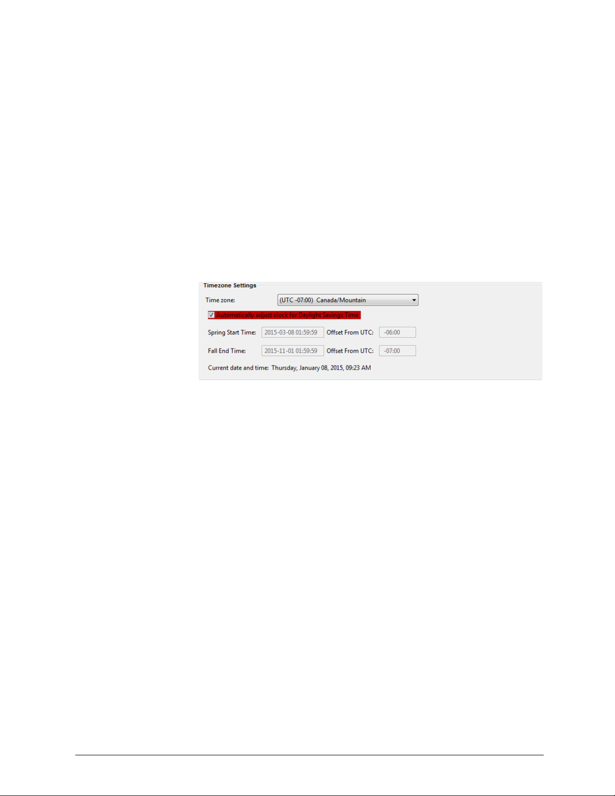
INTELLIDOX DOCKING MODULE USER MANUAL || CONFIGURE SETTINGS VIA FLEET MANAGER II SOFTWARE
Adjusting the Clock for Daylight Savings Time
After the module time is set via Fleet Manager II software, you may use Fleet Manager II
to configure module and detector clocks to automatically adjust for daylight savings time.
1. Set the module time. See Setting the Module Time on page 64.
Select the tab for a compatible detector and then select the IntelliDoX Configuration tab
for the compatible detector.
Under Timezone Settings, select Automatically adjust clock for Daylight Savings
Time.
Click the Time zone selector and then select a time zone from the drop down menu. The
next start and end dates for daylight savings time are displayed for the specified time
zone.
Review and revise other configuration settings if necessary, and then save the
configuration file and transfer it to one or more modules. For more information, see
Configure Module and Detector Settings on page 60.
HONEYWELL PAGE 66 OF 117
Find Quality Products Online at: sales@GlobalTestSupply.com
www.GlobalTestSupply.com
Page 68

INTELLIDOX DOCKING MODULE USER MANUAL || HIBERNATION
Hibernation
Hibernation is a factory-installed feature that is available for certain detectors
manufactured by Honeywell. When hibernation is activated, all detector safety functions
are disabled and the detector operating life countdown is suspended. Hibernation may
extend the service life of the detector, limited by the specified maximum operating life of
the detector. It does not extend the specified maximum operating life of the detector.
For more information, refer to the Fleet Manager II operator manual and the appropriate
detector operator manual.
HONEYWELL PAGE 67 OF 117
Find Quality Products Online at: sales@GlobalTestSupply.com
www.GlobalTestSupply.com
Page 69

INTELLIDOX DOCKING MODULE USER MANUAL || HIBERNATION
Configure Hibernation
You must use Fleet Manager II software to create a configuration file to activate
hibernation on insertion. After the configuration file is created, you can use Fleet Manager
II software or a USB flash drive to transfer the file to one or more modules. When a
module is configured to activate hibernation on insertion, the LCD changes to gray and the
hibernation symbol is displayed. All other module functions are disabled.
Detectors in hibernation mode do not respond to gas. Do not use detectors in
hibernation mode as personal protective equipment (PPE).
Work Plan: Configuring Hibernation
1. Create a hibernation configuration file.
Transfer the hibernation configuration file to one or more modules via Fleet Manager
II software, USB flash drive or Safety Suite Software.
Activate detector hibernation.
HONEYWELL PAGE 68 OF 117
Find Quality Products Online at: sales@GlobalTestSupply.com
www.GlobalTestSupply.com
Page 70
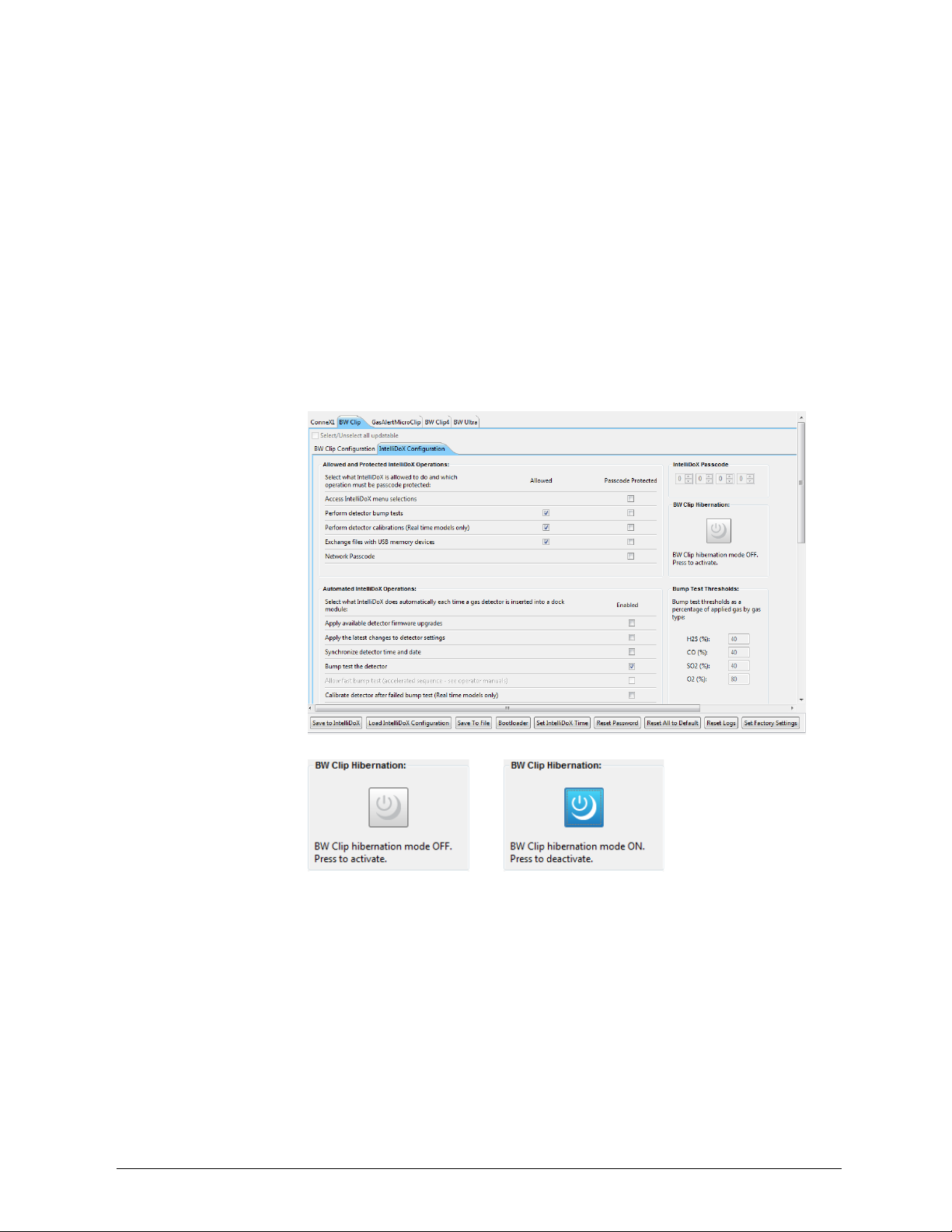
INTELLIDOX DOCKING MODULE USER MANUAL || HIBERNATION
Creating a Hibernation Configuration File via Fleet Manager II
1. Start Fleet Manager II software, and then log in as an administrator.
Select Configure Devices via IntelliDoX on the Devices menu. The IntelliDoX
Configuration Selection dialog box is displayed.
Select a configuration file and click OK. The IntelliDoX Device Configuration dialog box
is displayed.
Select the tab for a compatible detector that supports hibernation, and then select the
IntelliDoX Configuration tab.
Click the Hibernation icon to activate hibernation.
The hibernation activation dialog box is displayed. Click OK to save the setting, or click
Cancel to discard the changes.
7.- Click Safe to File. Save the configuration file to PC. Do not change the default file
name.
HONEYWELL PAGE 69 OF 117
Find Quality Products Online at: sales@GlobalTestSupply.com
www.GlobalTestSupply.com
Page 71

INTELLIDOX DOCKING MODULE USER MANUAL || HIBERNATION
Creating a Hibernation Configuration File via Safety Suite Software
1. From the main window, click IntelliDox Configuration.
2. From the IntelliDoX Configuration panel, select the Hibernation checkbox.
3. Click Save.
HONEYWELL PAGE 70 OF 117
Find Quality Products Online at: sales@GlobalTestSupply.com
www.GlobalTestSupply.com
Page 72

INTELLIDOX DOCKING MODULE USER MANUAL || HIBERNATION
Transferring a Hibernation Configuration File to a Module via Fleet Manager II Software
1. Create the hibernation configuration file. See Hibernation on page
Click Save to IntelliDoX. The IntelliDoX Selection dialog box is displayed.
Select one or more modules, and then click OK to transfer the hibernation configuration
file to the selected modules.
After the file is transferred, the Operation completed message box is displayed. Click OK
to return to the IntelliDoX Device Configuration dialog box.
Verify that the selected modules are configured for hibernation.
h. The LCD is gray.
i. The hibernation symbol is displayed.
Transferring a Hibernation Configuration File to a Module via USB Flash Drive
For connected modules, transfer the file to each appropriate module in the gang.
1. Insert a USB flash drive into a USB port on your PC. Use Windows Explorer or My
Computer to open the USB flash drive, and then create a new folder named System.
2. Create the hibernation configuration file. See Hibernation on page 67.
3. Click Save to File. The Save Settings to File dialog box is displayed.
4. Save the hibernation configuration file to the System folder on the USB flash drive.
Do not change the file name or extension. Eject the USB flash drive from the PC.
5. Insert the USB flash drive into the USB port on the module. The USB File Copy
Utility menu is displayed. Press or to select Copy to dock and then press to
continue.
6. The LCD changes to yellow. A progress bar and alternating Do not remove stick
and USB transfer in progress messages are displayed while the file is transferred.
7. After the transfer is successfully completed, the LCD changes to blue and the
USB File Copy Utility menu is displayed. Press or to select Exit and then
press to continue.
8. The LCD changes to green. Remove the USB flash drive from the port when
prompted.
9. Verify that the selected modules are configured for hibernation.
a. The LCD is gray.
b. The hibernation symbol is displayed.
HONEYWELL PAGE 71 OF 117
Find Quality Products Online at: sales@GlobalTestSupply.com
www.GlobalTestSupply.com
Page 73

INTELLIDOX DOCKING MODULE USER MANUAL || HIBERNATION
Activating Detector Hibernation
1. Verify that the module is configured for hibernation.
a. The LCD is gray.
b. The hibernation symbol is displayed.
Insert a compatible detector into the module. Detector identification is displayed on the
LCD.
After the detector is recognized, event logs are transferred to the module.
After the event log transfer is complete, hibernation is activated on the detector.
Remove the detector from the module and store for future use.
To learn more about hibernation, suitable conditions for detector storage, and detector
reactivation, refer to the appropriate detector operator manual.
HONEYWELL PAGE 72 OF 117
Find Quality Products Online at: sales@GlobalTestSupply.com
www.GlobalTestSupply.com
Page 74

INTELLIDOX DOCKING MODULE USER MANUAL || TRANSFER DATA FILES
Transfer Data Files
This section contains information and instructions related to transferring data files from
detectors to modules and from modules to a PC via Fleet Manager II software or
USB flash drive.
HONEYWELL PAGE 73 OF 117
Find Quality Products Online at: sales@GlobalTestSupply.com
www.GlobalTestSupply.com
Page 75

INTELLIDOX DOCKING MODULE USER MANUAL || TRANSFER DATA FILES
Transfer Data Files from the Module
Each module retains detailed, time-stamped data related to compliance test results and
module configuration events. The data are continuously updated, and stored in on-board
memory. When the on-board memory has reached capacity, the newest data replaces the
oldest data.
Each module also stores event logs and datalogs that are transferred from inserted
detectors. When the on-board memory has reached capacity, the newest logs replace the
oldest logs.
You can use Fleet Manager II software to transfer and manage data files, or you can
transfer the data files to a PC via USB flash drive. Data file transfers may take several
minutes to complete when multiple and/or large data files are transferred. For best results,
Honeywell recommends that you transfer data files periodically.
For more information, refer to the Fleet Manager II operator manual and the appropriate
detector operator manual.
Transferring Data Files via Fleet Manager II Software
You can use Fleet Manager II software to transfer data from modules that are activated
and connected to a network. Data files transferred via Fleet Manager II software are
added to the Fleet Manager II database. After the data files are transferred, you can use
Fleet Manager II to manage data and prepare custom reports.
1. Start Fleet Manager II software, and then log in as an administrator.
Select Import from the Devices menu. The Import Device Data window is displayed.
Select IntelliDoX Import. The Getting list of IntelliDoXs message box may be displayed
while Fleet Manager II prepares a list of available modules.
Select one or more modules. Select the file types to import, and then set a date range for
the records. Click Import. A downloading progress bar for each selected module is
displayed.
When all the progress bars are 100% complete, the Successfully downloaded logs
dialog box is displayed. Click OK to return to Fleet Manager II.
HONEYWELL PAGE 74 OF 117
Find Quality Products Online at: sales@GlobalTestSupply.com
www.GlobalTestSupply.com
Page 76

INTELLIDOX DOCKING MODULE USER MANUAL || TRANSFER DATA FILES
Scheduling Automatic Data File Transfers via Fleet Manager II Software
You can use Fleet Manager II software to schedule automatic data file transfers from
modules that are activated and connected to a network. Fleet Manager II software must
be operating on a PC that is connected to a computer network when the scheduled
transfer is initiated. Fleet Manager II automatically transfers data from specified modules
that are activated and connected to the network when the transfer is initiated.
1. Start Fleet Manager II software, and then log in as an administrator.
Select Import from the Devices menu. The Import Device Data window is displayed.
Select IntelliDoX Import. The Getting list of IntelliDoXs message box may be displayed
while Fleet Manager II prepared a list of available modules.
Click View/Edit Schedule. The Gathering the connection status of Scheduled
IntelliDoX message box is displayed while Fleet Manager II gathers information from
modules that are active and connected to the network.
After the module information is gathered, the Scheduled Import dialog box is displayed.
Select one or more modules from the Available IntelliDoX list, and then click Add to
Schedule. The selected modules are added to the Scheduled IntelliDoX list.
Set the date, time and occurrence options under Next Scheduled For.
Select the log file types to import under Select Logs.
Select Next Scheduled For options, and then select the logs to import.
Click Save to save the schedule settings. Fleet Manager II processes the scheduled
transfer at the specified date and time until the scheduled import is modified or deleted.
For more information, refer to the Fleet Manager II operator manual.
Transferring Data Files Manually via USB Flash Drive
1. For connected modules, you must transfer the data files from each module in the
gang.
Insert the USB flash drive into the USB port on the module. The USB File Copy Utility
menu is displayed.
Press or to select Copy from dock, and then press . The LCD changes to
yellow. A progress bar is displayed with alternating USB transfer in Progress and Do not
remove stick messages while the files are transferred.
After the transfer is successfully completed, the LCD changes to blue and the USB File
Copy Utility menu is displayed.
Press or to select Exit. The LCD changes to green and USB transfer complete and
Please remove stick are displayed. Remove the USB flash drive from the port.
Insert the USB flash drive into a USB port on a computer that contains Fleet Manager II
software.
Start Fleet Manager II software and then select Import from the Devices menu. The
Import Device Data window is displayed.
Select Directly From a File. Click Choose File to select one file for import from the USB
flash drive, or click Choose Directory to select all files in a named folder on the USB flash
drive. Click Import. A downloading progress bar is displayed.
When the progress bar reaches 100% complete, the Successfully Imported Files
message box is displayed. Click OK to return to Fleet Manager.
Repeat steps 7 and 8 until all data files are imported.
HONEYWELL PAGE 75 OF 117
Find Quality Products Online at: sales@GlobalTestSupply.com
www.GlobalTestSupply.com
Page 77

INTELLIDOX DOCKING MODULE USER MANUAL || UPDATE FIRMWARE
Update Module Firmware
Honeywell is committed to continuously improving product features and performance. As a
result, firmware updates may become available for the modules.
Updating Module Firmware via USB Flash Drive
Follow these instructions to update firmware for an individual module or a gang of up to
five connected modules. The update is processed only when the module or gang of
modules is idle.
For connected modules, you must transfer the firmware update to each module
in the gang.
1. Download and save the firmware update file to a PC or network drive. Do not
rename the file.
2. Transfer the update to a USB flash drive.
a. Insert a USB flash drive into a USB port on your PC. Use Windows
Explorer or My Computer to open the USB flash drive, and then create a
new folder named System.
b. Copy the firmware update to the System folder on the USB flash drive. Do
not change the file name or extension.
c. Eject the USB flash from the PC.
3. Transfer the file from the USB flash drive to a module.
a. Insert the USB flash drive into the USB port on the module. The USB File
Copy Utility menu is displayed.
b. Press or to select Copy to dock and then press to continue.
c. The LCD changes to yellow. A progress bar and alternating Do not
remove stick and USB transfer in progress messages are displayed
while the file is transferred.
d. After the transfer is successfully completed, the LCD changes to blue and
the USB File Copy Utility menu is displayed. Press or to select
Exit. Press to continue.
e. The LCD changes to green. Remove the USB flash drive from the port
when prompted.
4. The firmware update begins automatically when the module is idle. If the module is
part of a gang of connected modules, then installation begins after all of the
modules in the gang are idle.
5. The LCD changes to yellow. Installing new dock firmware. Please wait … is
displayed.
Do not deactivate the module during installation.
6. After the update is installed, updated modules restart automatically. IntelliDoX
reboot pending. Please wait… is displayed. After a few minutes, IntelliDoX
rebooting is displayed. The reboot takes about 5 seconds. The screen deactivates
briefly while the module restarts.
7. After the installation is complete, the LCD changes to green and Firmware
update complete is displayed.
8. Verify the version of the installed firmware.
HONEYWELL PAGE 77 OF 117
Find Quality Products Online at: sales@GlobalTestSupply.com
www.GlobalTestSupply.com
Page 78

INTELLIDOX DOCKING MODULE USER MANUAL || UPDATE FIRMWARE
a. Press and hold on the keypad until Adjust dock station settings is
displayed on the LCD.
b. Press or to select About, and then press . The About this
docking module summary screen is displayed.
c. Read the firmware version information.
d. Press to return to the Adjust dock station settings menu.
9. For connected modules, repeat steps 3 through 7 until all modules in the gang are
updated.
Updating Module Firmware via Fleet Manager II
When a module or gang of modules is connected to a network, you may transfer the
firmware update file to multiple selected modules via Fleet Manager II software. The
update is processed only when the module or gang of modules is idle. You can verify the
version of the installed firmware as well as other module details via the IntelliDoXs on the
Administration menu in Fleet Manager II.
For more information, refer to the Fleet Manager II operator manual.
1. Download and save the firmware update file to a PC or network drive. Do not rename
the file.
2. Start Fleet Manager II software, and then log in as an administrator.
3. Select Configure Devices via IntelliDoX on the Devices menu. The IntelliDoX
Configuration Selection dialog box is displayed.
4. Select a configuration file and click OK. The IntelliDoX Device Configuration dialog
box is displayed.
5. Click Bootloader at the bottom of the IntelliDoX Device Configuration dialog box. The
IntelliDoX Selection dialog box is displayed.Click Choose File. The Choose Firmware
File To Upload dialog box is displayed. Select the downloaded file, and then click
Open. The IntelliDoX Selection dialog box is displayed.
6. Select one or more IntelliDoX modules, and then click OK. A progress screen is
displayed while the firmware update file is automatically transferred to the selected
modules. When the transfer is complete, click OK to close the dialog box.
HONEYWELL PAGE 78 OF 117
Find Quality Products Online at: sales@GlobalTestSupply.com
www.GlobalTestSupply.com
Page 79

INTELLIDOX DOCKING MODULE USER MANUAL || UPDATE FIRMWARE
7. The firmware update begins automatically when the module is idle. The LCD changes
to yellow. Installing new dock firmware. Please wait … is displayed. Do not
deactivate the module during installation.
8. If the module is part of a gang of connected modules, then installation begins after all
of the modules in the gang are idle.
9. After the update is installed, updated modules restart automatically. IntelliDoX
reboot pending. Please wait… is displayed. After a few minutes, IntelliDoX
rebooting…. The reboot takes about 5 seconds. The screen deactivates briefly
before the module restarts.
10. After the installation is complete, the LCD changes to green and Firmware update
complete is displayed.
11. Verify the version of the installed firmware.
a. Select IntelliDoXs on the Administration menu in
Fleet Manager II software.
b. The Manage IntelliDoXs table is displayed.
Review the module information.
HONEYWELL PAGE 79 OF 117
Find Quality Products Online at: sales@GlobalTestSupply.com
www.GlobalTestSupply.com
Page 80

INTELLIDOX DOCKING MODULE USER MANUAL || UPDATE FIRMWARE
Update Detector Firmware
Honeywell is committed to continuously improving product features and performance. As a
result, firmware updates for detectors may become periodically available.
Work Plan: Updating Detector Firmware
1. Download and save the firmware update file to a PC or network drive. Do not rename
the file.
2. Transfer the firmware update to a module or gang of modules. See Transferring
Detector Firmware via USB Flash Drive or Transferring Detector Firmware via
Fleet Manager II.
3. Update the detector. See Update Detector Firmware.
4. Verify the firmware version. For more information, refer to the appropriate detector
operator manual.
Transferring Detector Firmware via USB Flash Drive
Follow these instructions to transfer detector firmware via USB flash drive to individual
modules, or to modules that are connected in a gang.
For connected modules, transfer the file to each appropriate module in the gang.
1. Download and save the firmware update file to a PC or network drive. Do not
rename the file.
2. Insert a USB flash drive into a USB port on your PC. Use Windows Explorer or My
Computer to open the USB flash drive, and then create a new folder named
System.
3. Copy the firmware update to the System folder on the USB flash drive. Do not
change the file name or extension. Eject the USB flash drive from the PC.
4. Verify that the detector firmware is appropriate for the module, and then transfer
the file.
a. Insert the USB flash drive into the USB port on the module. The
USB File Copy Utility menu is displayed.
b. Press or to select Copy to dock and then press to continue.
c. The LCD changes to yellow. A progress bar and alternating Do not
remove stick and USB transfer in progress messages are displayed
while the file is transferred.
d. After the transfer is successfully completed, the LCD changes to blue
and the USB File Copy Utility menu is displayed. Press or to
select Exit. Press to continue.
e. The LCD changes to green. Remove the USB flash drive from the port
when prompted.
HONEYWELL PAGE 80 OF 117
Find Quality Products Online at: sales@GlobalTestSupply.com
www.GlobalTestSupply.com
Page 81

INTELLIDOX DOCKING MODULE USER MANUAL || UPDATE FIRMWARE
Transferring Detector Firmware via Fleet Manager II
When a module or gang of modules is connected to a network, you may transfer the
detector firmware update file to multiple selected modules via Fleet Manager II software.
For more information, refer to the Fleet Manager II operator manual.
1. Download and save the firmware update file to a PC or network drive. Do not
rename the file.
2. Start Fleet Manager II software, and then log in as an administrator. Select
Configure Devices via IntelliDoX on the Devices menu. The IntelliDoX
Configuration Selection dialog box is displayed.
3. Select a configuration file and click OK. The IntelliDoX Device Configuration
dialog box is displayed.
4. Click Bootloader. The IntelliDoX Selection dialog box is displayed.
5. Click Choose File. The Choose Firmware File To Upload dialog box is
displayed. Select the downloaded file, and then click Open. The IntelliDoX
Selection dialog box is displayed.
6. Select one or more IntelliDoX modules, and then click OK. A progress screen is
displayed while the firmware update file is automatically transferred to the selected
modules.
7. When the transfer is complete, click OK to close the dialog box.
Updating the Detector Firmware
Modules must be configured via Fleet Manager II software to enable firmware updates on
insertion for compatible detectors. For more information, see Configure Module and
Detector Settings on page 37.
1. Insert a compatible detector into the module. Detector identification is displayed
on the LCD.
2. If the module is configured to perform a firmware update and other procedures on
insertion and a firmware update is available, then the detector event logs are
automatically transferred to the module and the firmware update begins.
3. The LCD changes to yellow. A progress bar and the Detector firmware upgrade
message are displayed.
4. After the upgrade is completed, the detector reboots. Alternating Detector
rebooting and Do not open lid messages are displayed.
5. When the reboot is successful, the LCD changes to green and the Firmware
upgrade complete message is displayed. Other procedures specified to occur
automatically on insertion are performed.
6. After all operations are completed, verify the firmware update.
a. Open the lid and remove the detector.
b. Verify the firmware version. For more information, refer to the
appropriate detector operator manual.
HONEYWELL PAGE 81 OF 117
Find Quality Products Online at: sales@GlobalTestSupply.com
www.GlobalTestSupply.com
Page 82

INTELLIDOX DOCKING MODULE USER MANUAL || UPDATE FIRMWARE
Updating the Detector Firmware via Safety Suite
When a new Firmware version is available, the user will get an UPDATE button under the
FIRMWARE VERSION section in the IntelliDoX Configuration panel.
Click UPDATE; Safety Suite will automatically select the file stored in the database and
proceed with the firmware upgrade.
After the firmware upgrades, the page will get refreshed, and a new version number will
be displayed.
HONEYWELL PAGE 82 OF 117
Find Quality Products Online at: sales@GlobalTestSupply.com
www.GlobalTestSupply.com
Page 83

INTELLIDOX DOCKING MODULE USER MANUAL || REPLACE DETECTOR CRADLE AND CALIBRATION INSERT
Replace Detector Cradle and Calibration Insert
This section contains information and instructions related to replacing an IntelliDoX
detector cradle and calibration insert.
HONEYWELL PAGE 83 OF 117
Find Quality Products Online at: sales@GlobalTestSupply.com
www.GlobalTestSupply.com
Page 84

INTELLIDOX DOCKING MODULE USER MANUAL || REPLACE DETECTOR CRADLE AND CALIBRATION INSERT
Upgrade the IntelliDoX to Fit Compatible Detectors
The IntelliDoX system is designed for users to upgrade their detector docking solution to
meet their changing needs. The IntelliDoX allows users to upgrade from one detector to
another with the replacement of the detector cradle and calibration insert.
What You Need to Replace the Detector Cradle and Calibration Insert
• A Philips screwdriver to remove the screws on the IntelliDoX
IMPORTANT: You must transfer data files from the IntelliDoX before you replace the
cradle and calibration insert.
Here's what you'll do to replace the cradle and calibration insert:
1. Transfer data from the IntelliDoX (see Transfer Data Files on page 73).
Update the firmware on the IntelliDoX to a compatible version, if required (see Update
Firmware on page 76).
Replace the cradle on the IntelliDoX.
Replace the calibration insert on the IntelliDoX.
HONEYWELL PAGE 84 OF 117
Find Quality Products Online at: sales@GlobalTestSupply.com
www.GlobalTestSupply.com
Page 85

INTELLIDOX DOCKING MODULE USER MANUAL || REPLACE DETECTOR CRADLE AND CALIBRATION INSERT
Replace the Detector Cradle
To replace the cradle, remove the cradle from the IntelliDoX (unscrew the screws and
unplug the connector), and then install the replacement cradle.
1. Disconnect the power cord, network cable, tubing, and inlet filter assemblies from the
IntelliDoX.
Use a screwdriver to unscrew the two screws from the cradle.
HONEYWELL PAGE 85 OF 117
Find Quality Products Online at: sales@GlobalTestSupply.com
www.GlobalTestSupply.com
Page 86

INTELLIDOX DOCKING MODULE USER MANUAL || REPLACE DETECTOR CRADLE AND CALIBRATION INSERT
Lift the cradle, hold the connector at the end of the cable, and pull to unplug the cable
from the circuit board.
Do not pull on the cable to unplug the cable. You can cause
damage to the cable. Hold the end connector.
Remove the cradle from the IntelliDoX.
Get the replacement cradle.
Plug the replacement cradle's connector cable into the circuit board.
Slide the replacement cradle's tabs under the IntelliDoX top assembly to place the cradle
into the IntelliDoX.
Use a screwdriver to fasten the two screws on the replacement cradle.
HONEYWELL PAGE 86 OF 117
Find Quality Products Online at: sales@GlobalTestSupply.com
www.GlobalTestSupply.com
Page 87

INTELLIDOX DOCKING MODULE USER MANUAL || REPLACE DETECTOR CRADLE AND CALIBRATION INSERT
Replace the Calibration Insert
To replace the calibration insert, remove the calibration insert from the IntelliDoX (unscrew
the screws and detach the gas tubes), and then install the replacement calibration insert.
1. Disconnect the power cord, network cable, tubing, and inlet filter assemblies from the
IntelliDoX.
Use a screwdriver to unscrew the two screws from the calibration insert.
Detach the two gas tubes from the IntelliDoX.
Remove the calibration insert.
Get the replacement calibration insert.
HONEYWELL PAGE 87 OF 117
Find Quality Products Online at: sales@GlobalTestSupply.com
www.GlobalTestSupply.com
Page 88

INTELLIDOX DOCKING MODULE USER MANUAL || REPLACE DETECTOR CRADLE AND CALIBRATION INSERT
Slide the calibration insert tabs under the IntelliDoX lid assembly to place the replacement
calibration insert into the IntelliDoX.
Use a screwdriver to fasten the two screws on the replacement calibration insert.
Connect the gas tubes to the IntelliDoX.
HONEYWELL PAGE 88 OF 117
Find Quality Products Online at: sales@GlobalTestSupply.com
www.GlobalTestSupply.com
Page 89

INTELLIDOX DOCKING MODULE USER MANUAL || MAINTENANCE
Maintenance
This section contains general information related to cleaning and maintenance,
replacement parts and accessories, and calibration equipment and accessories.
HONEYWELL PAGE 89 OF 117
Find Quality Products Online at: sales@GlobalTestSupply.com
www.GlobalTestSupply.com
Page 90

INTELLIDOX DOCKING MODULE USER MANUAL || MAINTENANCE
Clean and Maintain the Module
Before You Begin
1. Disconnect power before performing maintenance or cleaning.
To avoid personal injury or damage to the module, use only replacement parts and/or
accessories obtained from Honeywell or an authorized distributor.
No user-serviceable parts are inside the module.
If the module is damaged, contact Honeywell or an authorized distributor.
If the equipment is damaged or parts are missing, contact Honeywell immediately.
Substitution of components may impair the safety of the equipment.
Do not attempt to disassemble, adjust, or service the equipment unless instructions
are provided to perform a procedure, or a component is listed as a user-replaceable
component in the user manual. Use only Honeywell replacement components.
Do not expose the equipment to electrical shock or severe and/or continuous
mechanical shock.
Do not immerse the equipment in liquids.
Basic maintenance
To maintain the module in good operating condition, perform the following basic
maintenance as required:
1. Maintain a log of all maintenance that is performed.
Clean the exterior with a soft, damp cloth.
• Do not immerse in liquids.
• Do not use solvents, soaps or polishes.
Confirm that the inlet filter is free of dirt. Replace if required.
Once service is complete, reconnect the power supply. When power is connected, the
LCD activates and self-test is performed.
Replacement Parts and Accessories
Replaceable parts are sold separately. To receive a complete list of replaceable parts
approved for use with this product, contact Honeywell or an authorized distributor, or visit
Gas detectors, calibration and purge gas cylinders, and other accessories are sold
separately. To receive a complete list of calibration gases and accessories approved for
use with this product, contact Honeywell or an authorized distributor, or visit the product
HONEYWELL PAGE 90 OF 117
Find Quality Products Online at: sales@GlobalTestSupply.com
www.GlobalTestSupply.com
Page 91

INTELLIDOX DOCKING MODULE USER MANUAL || MAINTENANCE
Calibration Equipment and Gases
The use of calibration gas cylinders other than those specified by Honeywell may
result in unsafe calibration or possible non-recoverable failure of the equipment, and
will invalidate the warranty.
A demand flow regulator must be used with all calibration gas cylinder connections.
The module inlet should not be pressurized.
To receive a complete list of calibration gases and accessories approved for use with this
product, contact Honeywell or an authorized distributor, or visit the Order Information
2
Sticky gases (CL
bay. The user cannot perform calibration and bump tests from bay-2 to bay-5. And for that
configured inlet, IDOX will display as .
, NH3 and NO2) calibration and bump tests of are only allowed on first
HONEYWELL PAGE 91 OF 117
Find Quality Products Online at: sales@GlobalTestSupply.com
www.GlobalTestSupply.com
Page 92

INTELLIDOX DOCKING MODULE USER MANUAL || TECHNICAL SPECIFICATION AND WARRANTY
Technical Specification and Warranty
This section includes the technical specification and warranty for the module.
HONEYWELL PAGE 92 OF 117
Find Quality Products Online at: sales@GlobalTestSupply.com
www.GlobalTestSupply.com
Page 93

INTELLIDOX DOCKING MODULE USER MANUAL || TECHNICAL SPECIFICATION AND WARRANTY
Technical Specification
Dimensions
14.2 x 5.4 x 4.3 in (361 x 137 x 109 mm)
Weight
4.2 lb (1.9 kg)
Base system ingress protection
IP20
Enclosure
Impact resistant polycarbonate and acrylonitrile
butadiene styrene (PC+ABS)
Operating temperature
+50°F to +95°F (+10°C to +35°C)
Humidity
10% to 90% non-condensing
Altitude
Maximum 6 561 feet (2 000 meters)
Storage temperature
+14°F to +140°F (-10°C to +60°C)
Power supply
12 V 8.33A ITE power supply
Type of equipment
Process Control Equipment
Equipment class
Cord-connected, Class III
Pollution degree
2
Installation category
I
Mode of operation
Continuous
Real-time clock
Provides date and time stamp
Data storage
2 gigabytes of on-board memory
External interface
Ethernet
Pump flow rate
350 mL per minute
Calibration gas cylinder inputs
1 or 4 gas inlets
1 ambient air (purge) inlet
Automatic tests
Functional bump test; calibration; data transfer;
audible alarm; visual alarm
Configuration recognition
Automatic instrument and sensor
Alarm/calibration parameters
User-defined
Calibration gas connections
Built-in
Gas connection
3.2 mm (1/8 in) sub-miniature connect (SMC)
coupling
Solenoid
Built-in
LCD Background
Gray: Idle
Blue: Prompt for user action
Yellow: Activity in progress
Green: Activity completed
Red: Warning
Keypad
Scroll right
Scroll left
Scroll up
Scroll down
Press and hold until the module settings menu
is displayed. Press and release to select a
menu item or save changes.
Press and hold until an operation is cancelled.
Press and release to close a menu item or
return to a previous screen or cancel
changes.
Communications method
Two-way infrared between docking module and
detector
Ports
1 USB port
1 Ethernet port, for connection to a computer
network
Sensors
Audio and optical
Warranty
2 years beginning at date of shipment to the buyer
his symbol indicates that the product
T
must not be disposed of as general
industrial or domestic waste. This product
should be disposed of through suitable
WEEE disposal facilities. For more
information about disposal of this product,
contact your local authority, distributor or
the manufacturer.
HONEYWELL PAGE 93 OF 117
Find Quality Products Online at: sales@GlobalTestSupply.com
www.GlobalTestSupply.com
Page 94

FCC
NOTE: This equipment has been tested and found
to comply with the limits for a Class A digital
device, pursuant to part 15 of the FCC Rules.
These limits are designed to provide reasonable
protection against harmful interference when the
equipment is operated in a commercial
environment. This equipment generates, uses, and
can radiate radio frequency energy and, if not
installed and used in accordance with the
instruction manual, may cause harmful
interference to radio communications. Operation of
this equipment in a residential area is likely to
cause harmful interference in which case the user
will be required to correct the interference at his
own expense.
FCC CAUTION: Any changes or modifications not
expressly approved by the party responsible for
compliance could void the user's authority to
operate the equipment.
FCC / Industrie Canada Compliance
Cet appareil est conforme aux normes FCC
Partie 15 et normes RSS exemptes de licence
d’Industrie Canada. Son utilisation est soumise
aux deux conditions suivantes :
(1) cet appareil n’engendre pas d’interférences,
et
(2) cet appareil doit tolérer tout type
d’interférences, notamment les interférences
pouvant provoquer une utilisation non désirée de
l’appareil.
Find Quality Products Online at: sales@GlobalTestSupply.com
www.GlobalTestSupply.com
Page 95

INTELLIDOX DOCKING MODULE USER MANUAL || TECHNICAL SPECIFICATION AND WARRANTY
Limited Warranty and Limitation Liability
Honeywell LP (BW) warrants the product to be free from defects in material and
workmanship under normal use and service for a period of two years, beginning on the
date of shipment to the buyer. This warranty extends only to the sale of new and unused
products to the original buyer. BW’s warranty obligation is limited, at BW’s option, to
refund of the purchase price, repair or replacement of a defective product that is returned
to a BW authorized service center within the warranty period. In no event shall BW’s
liability here under exceed the purchase price actually paid by the buyer for the Product.
This warranty does not include:
• fuses, disposable batteries or the routine replacement of parts due to the normal wear
and tear of the product arising from use;
• any damage or defects attributable to repair of the product by any person other than
an authorized dealer, or the installation of unapproved parts on the product; or
• any product which in BW’s opinion, has been misused, altered, neglected or
damaged, by accident or abnormal conditions of operation, handling or use.
The obligations set forth in this warranty are conditional on:
• proper storage, installation, calibration, use, maintenance and compliance with the
product manual instructions and any other applicable recommendations of BW;
• the buyer promptly notifying BW of any defect and, if required, promptly making the
product available for correction. No goods shall be returned to BW until receipt by the
buyer of shipping instructions from BW; and
• the right of BW to require that the buyer provide proof of purchase such as the
original invoice, bill of sale or packing slip to establish that the product is within the
warranty period.
THE BUYER AGREES THAT THIS WARRANTY IS THE BUYER’S SOLE AND
EXCLUSIVE REMEDY AND IS IN LIEU OF ALL OTHER WARRANTIES, EXPRESS OR
IMPLIED, INCLUDING BUT NOT LIMITED TO ANY IMPLIED WARRANTY OF
MERCHANTABILITY OR FITNESS FOR A PARTICULAR PURPOSE. BW SHALL NOT
BE LIABLE FOR ANY SPECIAL, INDIRECT, INCIDENTAL OR CONSEQUENTIAL
DAMAGES OR LOSSES, INCLUDING LOSS OF DATA, WHETHER ARISING FROM
BREACH OF WARRANTY OR BASED ON CONTRACT, TORT OR RELIANCE OR ANY
OTHER THEORY.
Since some countries or states do not allow limitation of the term of an implied warranty,
or exclusion or limitation of incidental or consequential damages, the limitations and
exclusions of this warranty may not apply to every buyer. If any provision of this warranty
is held invalid or unenforceable by a court of competent jurisdiction, such holding will not
affect the validity or enforceability of any other provision.
Warranty Registration
HONEYWELL PAGE 95 OF 117
Find Quality Products Online at: sales@GlobalTestSupply.com
www.GlobalTestSupply.com
Page 96

INTELLIDOX DOCKING MODULE USER MANUAL || TROUBLESHOOTING
Troubleshooting
This section includes the troubleshooting instructions for the product.
HONEYWELL PAGE 96 OF 117
Find Quality Products Online at: sales@GlobalTestSupply.com
www.GlobalTestSupply.com
Page 97

INTELLIDOX DOCKING MODULE USER MANUAL || TROUBLESHOOTING
Compliance Tests
The sensor test fails during bump test or calibration.
The calibration gas cylinder is not connected to an inlet.
Connect an appropriate calibration gas cylinder to the inlet.
The calibration gas cylinder is empty.
Replace the empty calibration gas cylinder.
The end plate is not attached.
Attach an end plate to the last module in a gang (or to an individual module).
See Attach the End Plate.
If the end plate is damaged or missing, contact an authorized distributor.
The inlet key is not properly connected.
To connect the inlet key, see Inlet Keys.
The calibration gas cylinder tubing is too long.
Disconnect the tubing, cut it to a shorter length, and reconnect. See Connect a
Calibration Gas Cylinder.
The calibration gas cylinder tubing is damaged.
Inspect the tubing and replace with new tubing, if necessary.
The modules are not properly connected.
Lift the latch arm between modules and push the modules firmly together.
See Work Plan: Assemble Gangs of up to Five Connected Modules.
The gas type and/or concentration settings on the module are not configured to match the
calibration gas cylinder.
To configure gas inlets:
1. From the menu, select Settings.
2. Select an inlet, and verify that the gas type and concentration settings
match the connected calibration gas cylinder. See Configure Gas
Inlets.
The audible alarm test fails during bump test or calibration.
The detector's audible alarm hole is blocked.
To clean the audible alarm hole:
1. Remove the detector from the module.
2. Clean the audible alarm hole with a soft, damp cloth or an appropriate
cleaner that is specified in the detector operator manual.
The visual alarm test fails during bump test or calibration.
The detector's alarm LED windows are dirty.
To clean the indicators:
1. Remove the detector from the module.
2. Clean the alarm LED windows with a soft, damp cloth or an appropriate
cleaner that is specified in the detector operator manual.
The module is under too much light.
Move the module away from a direct light source.
HONEYWELL PAGE 97 OF 117
Find Quality Products Online at: sales@GlobalTestSupply.com
www.GlobalTestSupply.com
Page 98

INTELLIDOX DOCKING MODULE USER MANUAL || TROUBLESHOOTING
Detectors fail to zero.
Background gas is present.
Connect the purge inlet to a clean air supply.
A calibration gas cylinder is connected to the purge inlet.
Disconnect the calibration gas cylinder from the purge inlet, and connect the
cylinder to a gas inlet. See Connect a Calibration Gas Cylinder.
HONEYWELL PAGE 98 OF 117
Find Quality Products Online at: sales@GlobalTestSupply.com
www.GlobalTestSupply.com
Page 99

INTELLIDOX DOCKING MODULE USER MANUAL || TROUBLESHOOTING
Detectors
The detector firmware is not updated after a new firmware update file is transferred via USB flash drive.
The file name is incorrect.
The firmware update file name is not the same as the downloaded file name.
Rename the file name to match the name of the downloaded firmware update
file, or download a new firmware update file. See Update Firmware.
The file is not in the System folder on the USB flash drive.
Create a folder called System on the USB flash drive. Move the file to
the System folder. See Updating Module Firmware via USB Flash Drive.
Update Detector Firmware is not enabled via Fleet Manager II software.
Use software to enable detector firmware updates. Transfer the modified
configuration file to the appropriate modules.
The firmware on the detector is the same version as the firmware update.
Verify that the firmware file on the USB flash drive is the most recent firmware
version. See Update Firmware.
The detector time is incorrect, or is not the same as the module time.
Use software to enable the Synchronize detector time and date option.
See Adjust Time and Date Settings via Fleet Manager II Software and in
the Automated Operations section, select Synchronize detector time and date.
The module time was not set via Fleet Manager II.
Use software to set the module time. See Adjust Time and Date Settings via
Fleet Manager II Software.
The time zone is incorrect.
Use software to select the time zone. See Adjust Time and Date Settings via
Fleet Manager II Software.
Daylight Savings Time did not work
The module Daylight Savings Time was not set.
Use software to automatically adjust clock for Daylight Savings Time. See Adjust
Time and Date Settings via Fleet Manager II Software.
The time zone is incorrect.
Use software to select the time zone. See Adjust Time and Date Settings via
Fleet Manager II Software.
The module time was not set via Fleet Manager II.
Use software to set the module time. See Adjust Time and Date Settings via
Fleet Manager II Software.
HONEYWELL PAGE 99 OF 117
Find Quality Products Online at: sales@GlobalTestSupply.com
www.GlobalTestSupply.com
Page 100

INTELLIDOX DOCKING MODULE USER MANUAL || TROUBLESHOOTING
Modules
Modules do not assemble into a gang.
The O-rings on the inlet connections are dry.
Apply the supplied lubricant to the O-rings. See Work Plan: Assemble Gangs
of up to Five Connected Modules. To order additional lubricant, contact an
authorized distributor.
Modules do not attach to mounting DIN rails.
The DIN rail mounting screws are too tight.
Loosen the mounting screws slightly, and then mount the modules. See Mount
on Parallel DIN Rails.
Modules in a gang do not activate when the power is connected.
The modules are not firmly connected.
Verify that connected modules are firmly connected and latch arms are lowered
and locked. See Work Plan: Assemble Gangs of up to Five Connected
Modules.
The module connector is damaged.
Inspect the module connector pins. If the pins are damaged, contact an
authorized distributor.
You smell gas in the vicinity of the module.
A demand flow regulator is not correctly connected to the calibration gas cylinder.
Check the connection between the regulator and the gas cylinder.
The exhaust tubing is not attached or is blocked.
Verify that the exhaust tubing is firmly attached and free of defects or
obstructions. See Connect the Exhaust Tubing.
The exhaust tubing is not venting to an appropriate area.
Verify that the exhaust tubing is not connected to a negative pressure system.
Verify that the free end of the tubing is positioned to vent to an appropriate area.
The LCD changes to red and a pump alarm error message is displayed.
The calibration gas cylinder is empty.
Replace the calibration gas cylinder with a filled calibration gas cylinder.
The tubing that connects the module to the calibration gas cylinder is too long.
To shorten the tubing:
1. Disconnect the tubing.
2. Cut it to a shorter length.
3. Move the calibration gas cylinder closer to the module, and attach the
tubing.
The tubing that connects the module to the calibration gas cylinder is blocked.
Verify that the tubing is free of defects and obstructions. Replace if necessary.
The diameter of the tubing that connects the calibration gas cylinder to the module is too
small.
Replace the tubing with tubing that has a larger diameter.
HONEYWELL PAGE 100 OF 117
Find Quality Products Online at: sales@GlobalTestSupply.com
www.GlobalTestSupply.com
 Loading...