

Page 1

Operator’s Manual
Single Gas Detector
Page 2

Page 3

ConneX1 Operator’s Manual i
Limited Warranty and Limitation Liability
BW Technologies by Honeywell LP (BW) warrants the product to be free from defects in material and workmanship under nor mal use and service for a period of
two years, beginning on the date of shipment to the buyer. This warranty extends only to the sale of new and unused products to the original buyer. BW’s warranty
obligation is limited, at BW’s option, to refund of the purchase price, repair or replacement of a defective product that is returned to a BW authorized service center
within the warranty period. In no event shall BW’s liability hereunder exceed the purchase price actually paid by the buyer for the Product.
This warranty does not include:
a. fuses, disposable batteries or the routine replacement of parts due to the normal wear and tear of the product arising from use;
b. any product which in BW’s opinion, has been misused, altered, neglected or damaged, b y accident or abnormal conditions of operation, handling or use; or
c. any damage or defects attributable to repair of the product by any person other than an authorized dealer, or the installation of unapproved parts on the
product.
The obligations set forth in this warranty are conditional on:
a. proper storage, installation, calibration, use , maintenance and compliance with the product manual instructions and an y other applicable recommendations
of BW;
b. the buyer promptly notifying BW of any defect and, if required, promptly making the product available for correction. No goods shall be returned to BW
until receipt by the buyer of shipping instructions from BW; and
c. the right of BW to require that the buyer provide proof of purchase such as the original invoice, bill of sale or packing slip to establish that the product is
within the warranty period.
The buyer agrees that this warranty is the buyer’s sole and exclusive remedy and is in lieu of all other warranties, express or implied, including but not limited to any
implied warranty of merchantability or fitness for a particular purpose. BW shall not be liable f or an y special, indirect, incidental, lost profits, or consequential damages
or losses, including loss of data, whether arising from breach of warranty or based on contract, tort or reliance or any other theory.
Since some countries or states do not allow limitation of the term of an implied warranty , or exclusion or limitation of incidental or consequential damages , the limitations
and exclusions of this warranty ma y not apply to ev ery buyer . If any provision of this warranty is held invalid or unenf orceable b y a court of competent jurisdiction, such
holding will not affect the validity or enforceability of any other provision.
Page 4

ConneX1 Operator’s Manualii
Contacting BW Technologies by Honeywell
Corporate Headquarters
BW Technologies by Honeywell
2840 2nd Ave. SE
Calgary, AB
Canada T2A 7X9
+1.403.248.9226 / 1.800.663.4164
+1.403.573.3708
United States
BW Technologies by Honeywell
405 Barclay Blvd.
Lincolnshire, IL
USA 60069
+1.847.955.8200 / 1.800.538.0363
+1.847.955.8210
Europe
BW Technologies by Honeywell
4 Stinsford Road
Nuffield Industrial Estate
Poole, Dorset BH17 0RZ
+44 (0) 1295.700.300
+44 (0) 1295.700.301
info@gasmonitors.com
www.gasmonitors.com
Page 5

ConneX1 Operator’s Manual iii
Table of Contents
1. Introduction ....................................................................................1
1.1 Intended Use
...........................................................................1
1.2 Product Overview
....................................................................2
1.2.1 Parts of the ConneX1
..................................................2
1.2.2 Display Elements .........................................................3
1.2.3 Buttons .........................................................................4
1.3 Sensor Poisons and Contaminants .........................................5
2. Getting Started
...............................................................................6
2.1 Activating/Deactivating the Detector
.......................................6
3. Installing Fleet Manager II
...........................................................11
3.1 Using Fleet Manager II to Configure the Detector
.................11
4. User Options
................................................................................13
4.1 General User Options
...........................................................13
4.1.1 Message Configuration
..............................................15
4.1.2 Mandown Configuration .............................................15
4.1.3 Password Configuration ............................................15
4.2 Sensor and Profile Configuration ..........................................16
4.2.1 Profile Options
...........................................................16
4.2.2 Sensor Options ..........................................................16
4.3 Network Information Options ................................................19
5. Mandown Alarm
...........................................................................20
5.1 Break Mode
...........................................................................20
6. Panic Alarm
..................................................................................21
7. Alarms...........................................................................................21
7.1 Alarm Setpoints
.....................................................................24
7.2 Stopping a Gas Alarm
...........................................................24
7.2.1 Low and High Alarms.................................................24
7.2.2 TWA and STEL Alarms
..............................................24
7.2.3 Acknowledging Latching Alarms ................................24
8. Modes ...........................................................................................25
8.1 Standard Operation
...............................................................25
8.2 Stealth Mode
.........................................................................25
8.3 Safe Mode
.............................................................................25
8.4 Review Mode
........................................................................25
8.4.1 Gas Exposure
............................................................25
8.4.2 Sensor Details ...........................................................26
8.4.3 Detector Details .........................................................26
8.4.4 Messages ..................................................................26
9. Calibration ....................................................................................26
9.1 Calibration Using the IntelliDoX
............................................26
9.2 Calibration Guidelines
...........................................................26
9.3 Installing the Calibration Cap
................................................27
9.3.1 Gas Cylinder Connection
...........................................27
9.3.2 Calibration Gas Concentration ...................................27
9.4 Manual Calibration Procedure ...............................................28
Page 6

ConneX1 Operator’s Manualiv
10. Bump Test ...................................................................................30
10.1 Bump Test Using the IntelliDoX
...........................................30
10.2 Performing a Manual Bump Test
.........................................30
11. Datalogs......................................................................................32
12. Event Logs
.................................................................................32
13. Messaging
..................................................................................32
13.1 Receiving Messages
...........................................................32
13.2 Reading Messages
.............................................................33
13.2.1 Sending Messages
..................................................33
13.3 Panic Alarm Messages .......................................................33
14. LocaXion Manager
.....................................................................34
15. Fleet Manager II..........................................................................34
15.1 Downloading Data To Fleet Manager II
...............................34
15.2 Upgrading the Firmware
......................................................34
15.3 Generating Calibration Certificates
.....................................34
16. Maintenance
...............................................................................34
16.1 Charging the Rechargeable Battery
....................................35
16.1.1 Optimum Battery Operation
.....................................36
16.1.2 Rechargeable Battery Capacity ...............................36
16.2 Replacing the Sensor and Sensor Filter .............................36
16.2.1 Replacing the Sensor
..............................................38
16.2.2 Replacing the Sensor Filter .....................................38
17. WEEE Directive and Battery Directive
.....................................39
17.1 Removal and Disposal of the Rechargeable Battery.
.........39
18. T roubleshooting
.........................................................................41
19. Replacement Parts and Accessories
.......................................53
20. Specifications
............................................................................54
Appendix A Regional Setpoints
.....................................................56
A.1 North America
......................................................................56
Appendix B Configuration Menu Structure
...................................57
Appendix C Review Mode Menu Structure....................................58
Appendix D Datalog Information
....................................................59
Appendix E Event Log Information
................................................59
Page 7

ConneX1 Operator’s Manual v
a Cautions
• Warning: Substitution of components may impair Intrinsic Safety
• Before using the detector, refer to Sensor Poisons and Contaminants.
• Caution: For safety reasons, this equipment m ust be operated and serviced
by qualified personnel only. Read and understand the operator’s manual
completely before operating or servicing.
• Charge the detector before first-time use. BW Technologies by Honeywell
recommends the detector be charged after every workday.
• Calibrate the detector before first-time use and then on a regular schedule,
depending on use and sensor exposure to poisons and contaminants. BW
T echnologies by Honeyw ell recommends that the sensor should be calibrated
regularly and at least once every 180 days (6 months).
• Calibrate only in a safe area that is free of hazardous gas in an atmosphere
of 20.9% oxygen.
• BW Technologies by Honeywell recommends to bump test the sensor bef ore
each day’s use to confirm its ability to respond to gas by exposing the
detector to a gas concentration that exceeds the alarm setpoints. Manually
verify that the audible, visual, and vibrator alarms are activated. Calibrate
if the readings are not within the specified limits.
• Any rapid upscaling reading followed by a declining or erratic reading
may indicate a gas concentration beyond upper scale limit, which can be
hazardous.
• For use only in potentially explosive atmospheres where oxygen
concentrations do not exceed 20.9% (v/v).
• Extended exposure of the detector to certain concentrations of combustible
gases and air may stress an detector element that can seriously affect its
performance. If an alarm occurs due to high concentration of combustible
gases, calibrate the detector. If necessary, replace the sensor.
• Warning: The lithium batter y may present a risk of fire or chemical burn
hazard if misused. Do not disassemble, heat above 212°F (100°C), or
incinerate.
• Warning: Lithium polymer cells exposed to heat at 266°F (130°C) for 10
minutes can cause fire and/or explosion.
• e Warning: This detector contains a lithium polymer battery. Dispose of
used lithium cells immediately . Do not disassemble. Do not dispose of in fire.
Do not mix with the solid waste stream. Spent batteries must be disposed
of by a qualified recycler or hazardous materials handler.
• Keep lithium cells away from children.
• Deactivating the detector by removing the battery pack may cause improper
operation and harm the detector.
• e Warning: At the end of their working lives , sensors must be disposed
of in an environmentally safe manner, in accordance with local waste
management requirements and environmental legislation. Do NO T incinerate
sensors as they may emit toxic fumes.
Page 8

Page 9
ConneX1 Operator’s Manual 1
Introduction
1. Introduction
The ConneX1 is a compact, portable gas detector designed to be carried or worn
without hindering the user. Its purpose is to continuously monitor the atmosphere
continuously for hazardous levels. Audible, visual, and vibratory alarms alert the
user to danger when hazardous conditions are detected.
1.1 Intended Use
The ConneX1 has been designed to alert the user to potentially hazardous
atmospheres while carrying out his/her normal duties. Therefore, the detector
must be kept switched on and worn as close to the breathing area as possible,
and several accessories are provided to allow the detector to be w orn in a number
of different ways:
a. On the chest
b. On a belt
The detector is provided with various methods to enable the user to comply safely
and easily with confined space regulations.
CAUTION
BW recommends that the detector be calibrated at least every 6
months or in accordance with customer site procedures, whichever
is sooner. Correct operation of the detector should be conrmed with
test gas of known concentration before each use.
The use of the IntelliDoX accessory is strongly recommended as it
enables a calibration to be performed quickly and easily.
WARNING
A sensor which cannot be calibrated or which is found to be out of
tolerance should be replaced immediately.
Page 10
ConneX1 Operator’s Manual2
Introduction
1.2 Product Overview
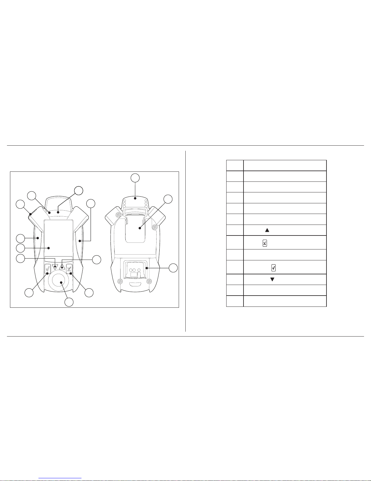
1.2.1 Parts of the ConneX1
3
4
5
2
6
7
8
9
10
11
2
12
2
11
Figure 1. Parts of ConneX1
Table 1. Parts of ConneX1
Item Description
1 Condence ash
2 Alarm LED
3 Antenna
4 Belt clip
5 Charge connection/IR Link inferface
6
Up button
7
X button
8
Sensor
9
Check button
10
Down button
11
LCD
12 Beeper
Page 11
ConneX1 Operator’s Manual 3
Introduction
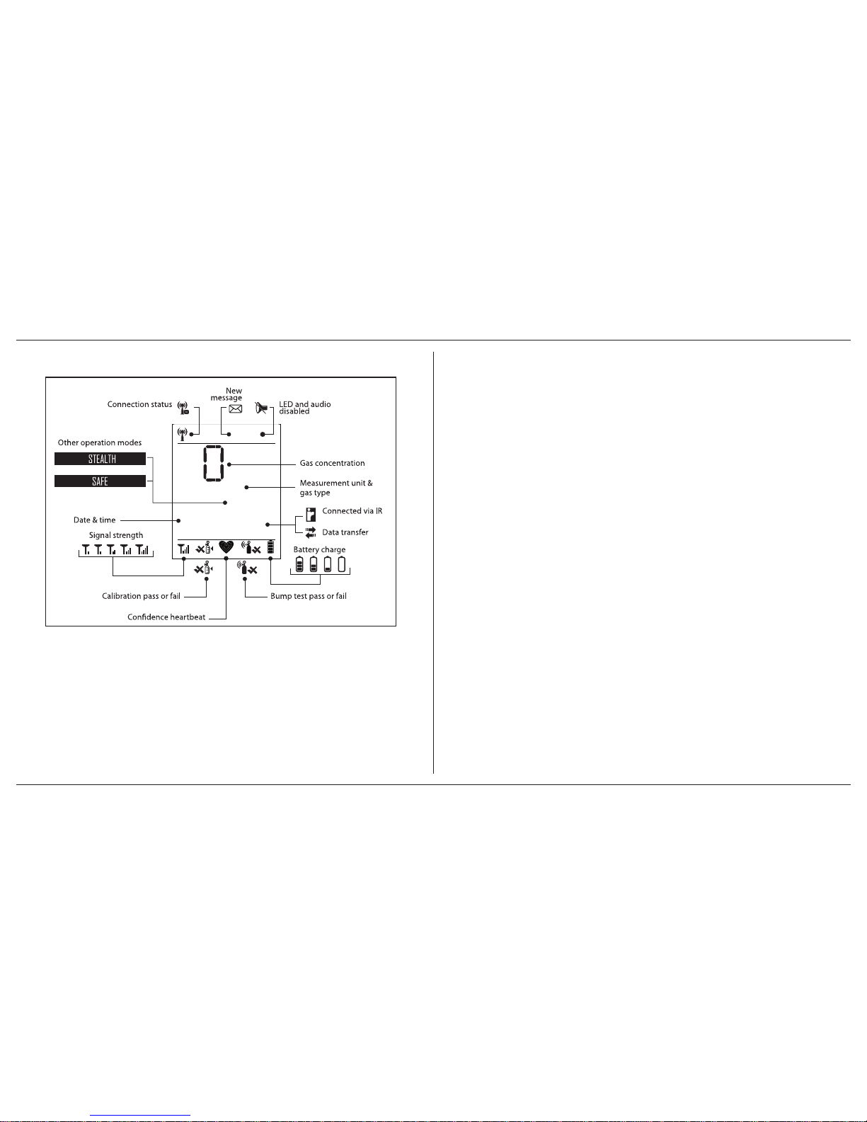
1.2.2 Display Elements
10/13/12
11:21 am
ppm - H2S
Page 12
ConneX1 Operator’s Manual4
Introduction
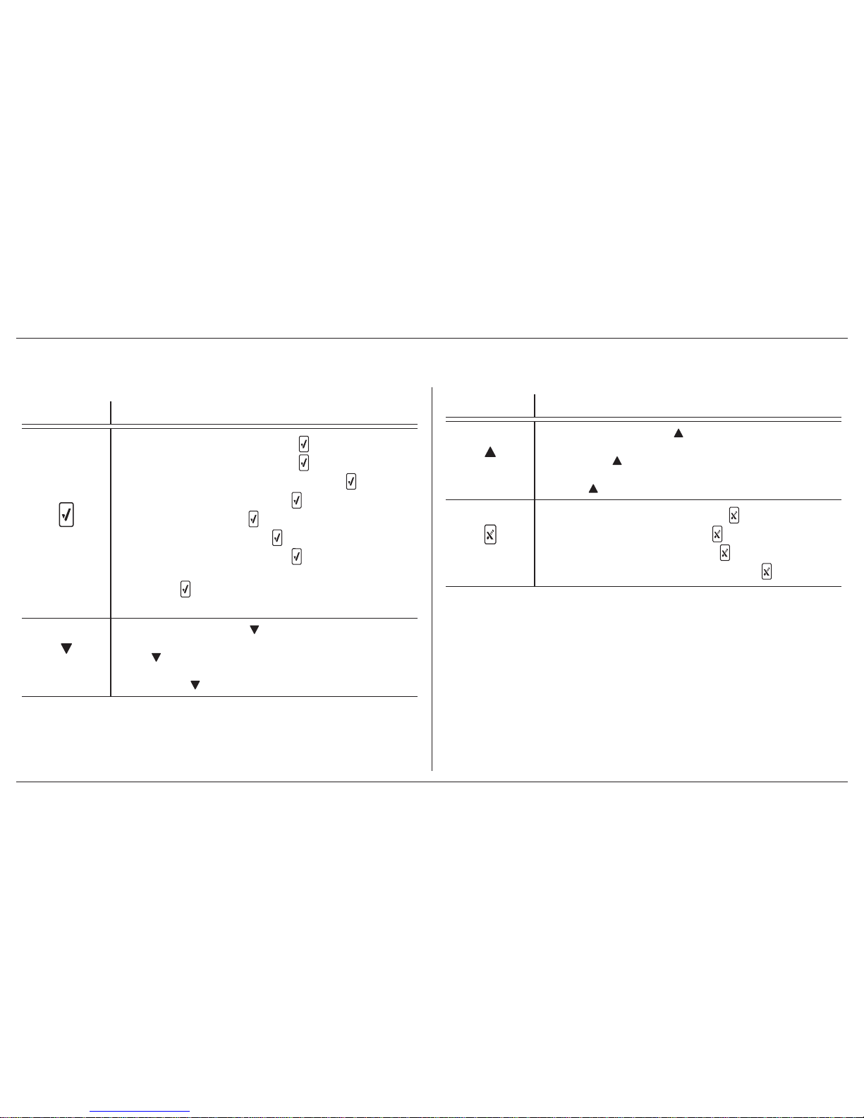
1.2.3 Buttons
Table 2. Pushbuttons
Button Description
Check
• To power on the detector, press and hold for 3 seconds
• To power off the detector, press and hold for 5 seconds
• To read a message when the pop up displays, press
• To enter the Conguration menu, press
• To select a menu item, press
• To select a menu command, press
• To acknowledge a latched alarm, press
• To acknowledge a low alarm and temporarily disable the audible
alarm, press
. The Low Alarm Acknowledgement option must be
enabled in Fleet Manager II
Down
• To enter Quick Review, press
• To decrement the displayed value, scroll down, scroll through digits,
press
• To scroll down an entire screen in Operator and Location menus,
press and hold
Table 2. Pushbuttons
Button Description
Up
• To enter Review Mode, press
• To increment the displayed value, scroll up, or move the cursor to
the right press
• To scroll up an entire screen in Operator and Location menus, press
and hold
X
• To generate a panic alarm, press and hold for 4 seconds
• To clear a panic alarm, press and hold for 4 seconds
• To move to a previous menu level, press
• To abort a menu command while in a menu, press
Page 13
ConneX1 Operator’s Manual 5
Introduction
1.3 Sensor Poisons and Contaminants
Several cleaners, solvents, and lubricants can contaminate and cause permanent
damage to the sensor. Before using cleaners, solvents, and lubricants in close
proximity to the sensor, read the following cautions and refer to Table 3.
CAUTION
Use only the following BW Technologies by Honeywell recommended
products and procedures:
• Use water-based cleaners.
• Use non-alcohol based cleaners.
• Clean the exterior of the detector with a soft, damp cloth
• Do not use soaps, polishes, or solvents
The following table lists common products to avoid using around sensor.
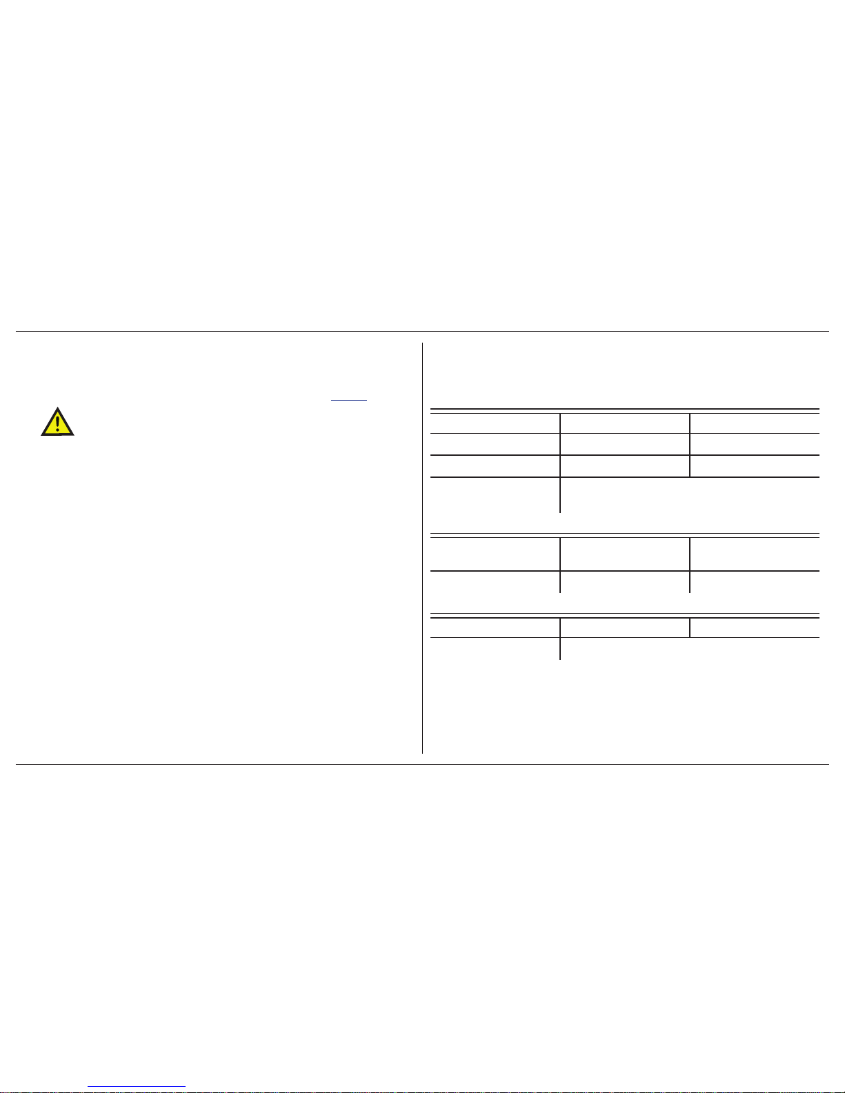
Table 3. Sensor Poisons and Contaminants
Cleaners and Lubricants
Brake cleaners Lubricants Rust inhibitors
Window and glass cleaner Dishsoaps Citrus-based cleaners
Alcohol-based cleaners Hand sanitizers Anionic detergents
Methanol (fuels and
antifreezes)
Silicones
Silicone cleaners and
protectants
Silicon based adhesives,
sealants, and gels
Hand/body and medicinal
creams that contain silicone
Tissues containing silicone Mold releasing agents Polishes
Aerosols
Bug repellents and sprays Lubricants Rust inhibitors
Window and glass cleaners
Page 14
ConneX1 Operator’s Manual6
Getting Started
2. Getting Started
2.1 Activating/Deactivating the Detector
CAUTION
Only activate the detector in a fresh air environment.
Activate: Press and hold for 3 second
Deactivate: Press and hold for 5 seconds.
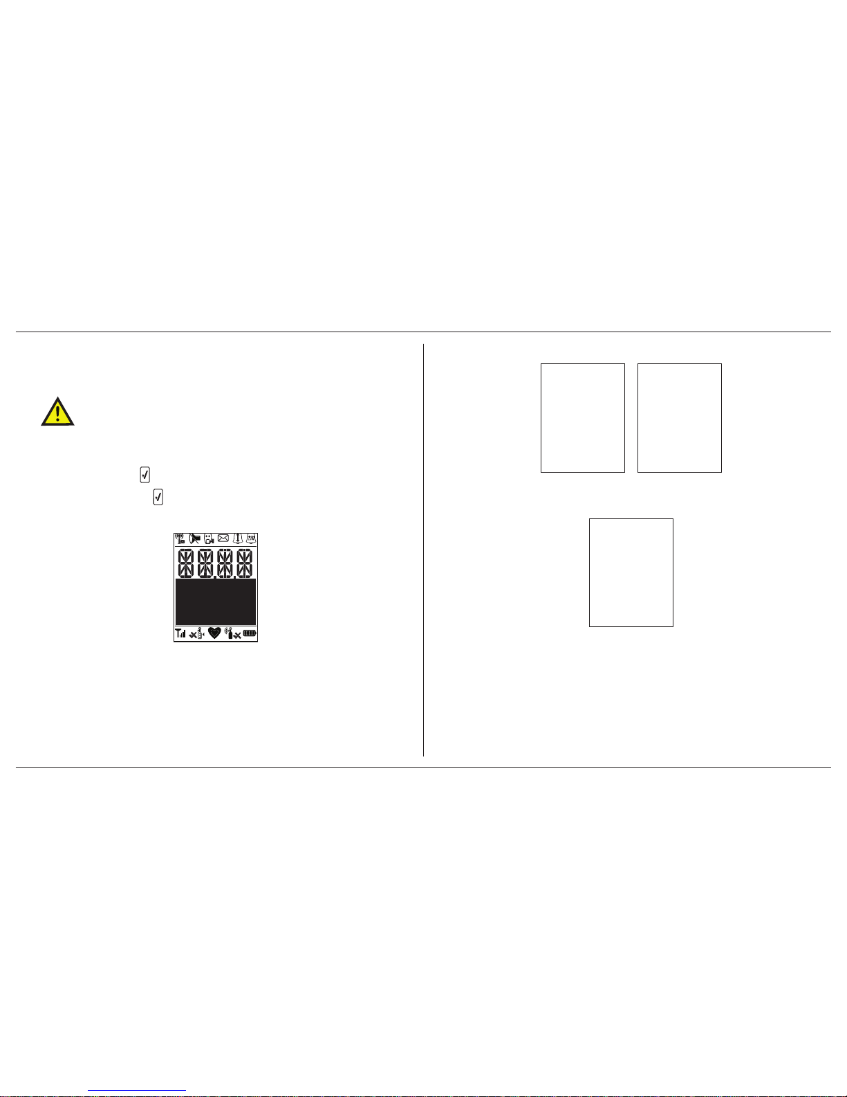
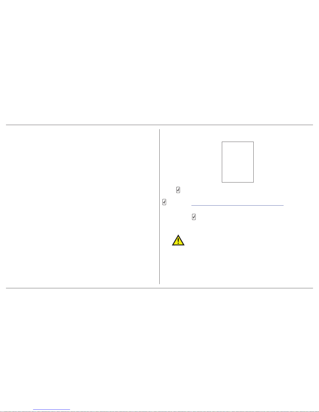
1. The Segment Testing screen displays.
2. The Splash screen displays.
At this time the detector is running a self-test and auto zero on the sensor.
3. The firmware version, hardware version, and serial number displays.
Page 15

ConneX1 Operator’s Manual 7
Getting Started
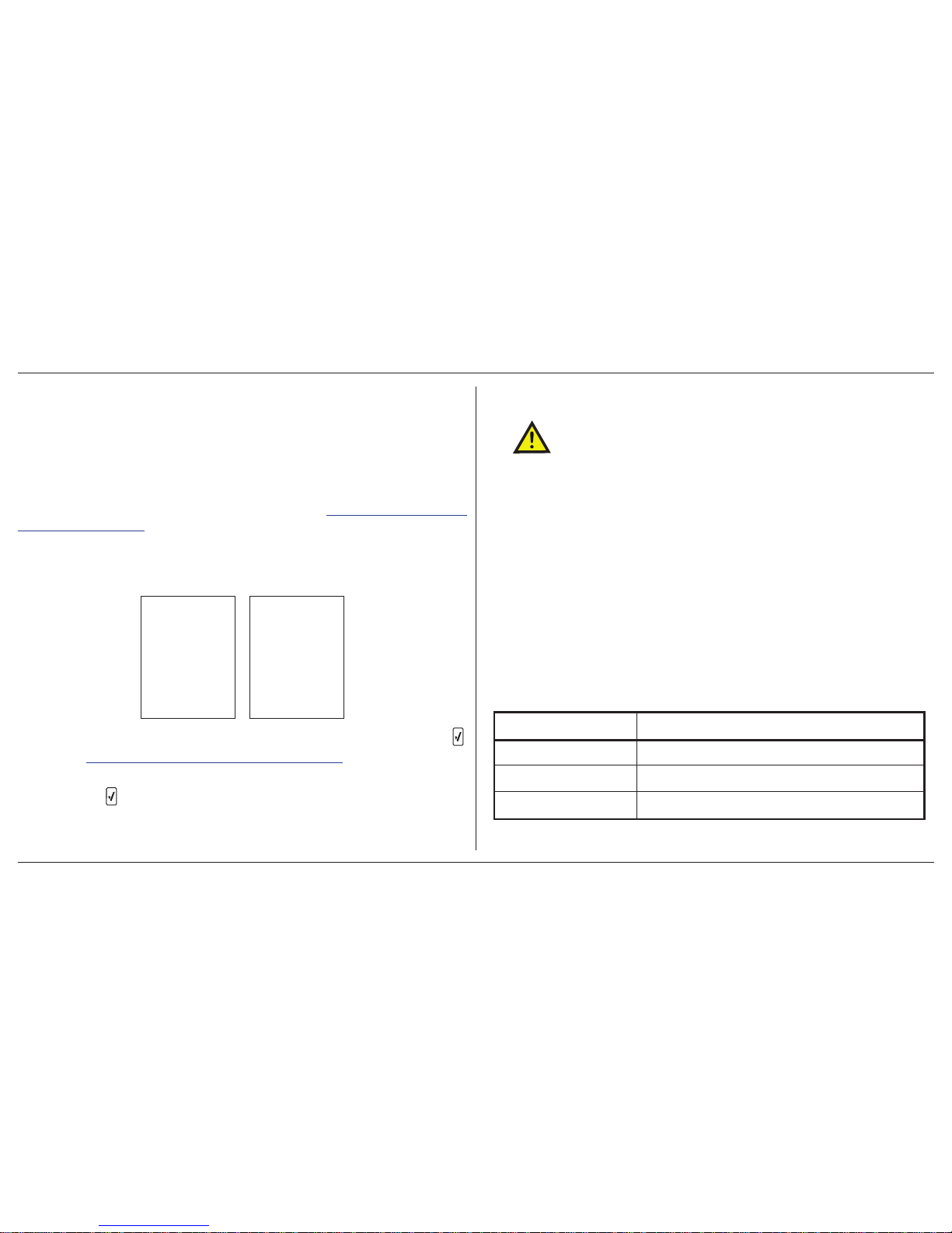
4. If a startup message is enabled in Fleet Manager, the text displays.
5. The current profile, operation mode, and Wi-Fi mode display. For more
information on profiles, refer to 4.2 Sensor and Profile Configuration on
page 16.
6. The detector presents the opportunity to select a different operator. To
confirm the selection, press
or and then to select a different operator .
7. The detector presents the opportunity to select a new location. To confirm
the selection, press
or and then to select a different location.
Page 16

ConneX1 Operator’s Manual8
Getting Started
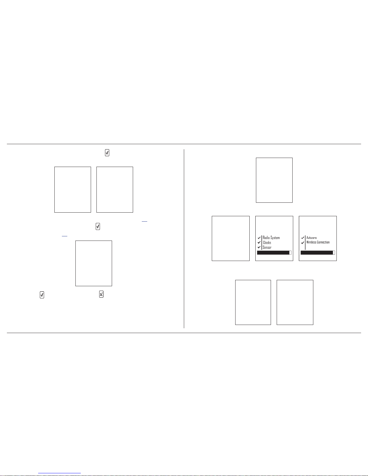
8. The screen then displays the measuring range, TW A Alarm, STEL Alarm,
Low Alarm, and High Alarm.
9. The detector then completes the sensor self-test.
10. If Auto Zero is enabled, the sensor begins to auto zero.
Page 17

ConneX1 Operator’s Manual 9
Getting Started
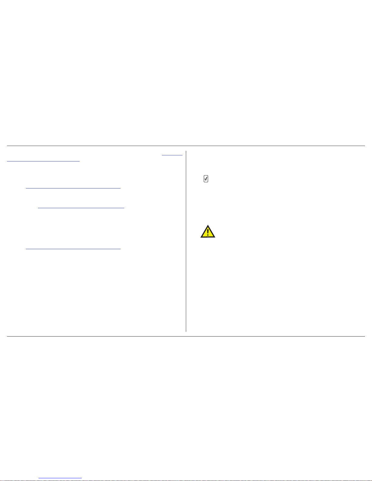
11. If the last calibration failed, press to acknowledge. If the failure is not
acknowledged, the detector powers off.
12. If the calibration is overdue, press to acknowledge. If calibration is not
overdue, proceed to step #13.
(Note: “ To start” alternates with “ To continue” every 4 seconds.)
If Force Calibration is enabled, a calibration must be completed before entering
normal operation. If a calibration is not perfor med, the detector automatically
powers off.
13. If Cal Reminder is enabled, the screen displays the number of da ys before
a calibration should be performed.
If Cal Reminder is not enabled, the Calibration Interval displays. Proceed
to step #15.
Page 18
ConneX1 Operator’s Manual10
Getting Started
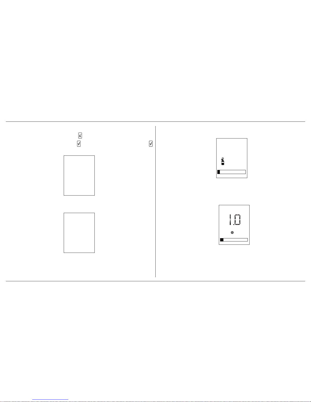
14. If the last bump test failed, press to accept. If the failure is not
acknowledged, the detector powers off.
If the last bump test was successful, proceed to step #16.
15. If the bump test is overdue, press to accept. If bump test is not ov erdue,
proceed to step #16.
(Note: “ To start” alternates with “ To continue” every 4 seconds.)
If Force Bump Test is enabled, a bump test must be completed before
entering normal operation. If a bump test is not performed, the detector
automatically powers off.
16. The screen displays the number of days until the next bump test.
17. The detector displays a startup summary.
18. If the startup summary is error-free, the screen displays that the startup
sequence is finished. The detector then enters normal operation.
Page 19
ConneX1 Operator’s Manual 11
Installing Fleet Manager II
3. Installing Fleet Manager II
Fleet Manager II is required to configure the detector. To install Fleet Manager II,
refer to the Fleet Manager II CD-ROM that includes the
• installation wizard, and
• Fleet Manager II Operator’s Manual (located under Help)
3.1 Using Fleet Manager II to Configure the
Detector
1. Activate the detector and wait for the startup sequence to complete.
2. Connect the USB cable to the USB port of the computer.
NOTE Plug the USB into the same USB port where the USB drivers
were installed.
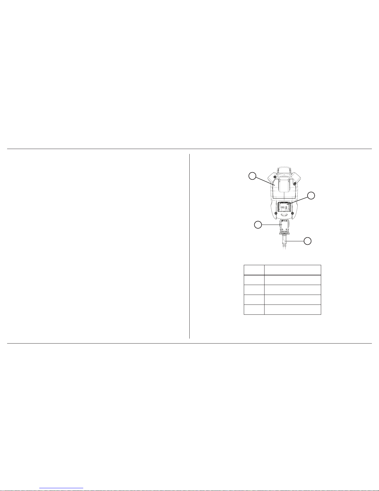
3. Connect the USB cable to the IR Link.
4. Insert the IR Link into the IR interface on the back of the detector.
Figure 2. Connecting the IR Link
1
2
3
4
Table 4. Connecting the IR Link
Item Description
1 Detector
2 IR Link interface
3 IR Link
4 USB cable
Page 20

ConneX1 Operator’s Manual12
Installing Fleet Manager II
5. From the PC, open Fleet Manager II.
The following screen displays when the IR Link is connected to the detector .
6. Click Administration.
7. From the Administration toolbar, click Login / Logout to access the
Enter Password dialog box. Enter Admin and click OK (password is
case sensitive).
8. From the Devices toolbar, click Configure Device via IR Link.
9. The Device selection popup displays. Select ConneX1 and click OK.
10. From the configuration window, click Retrieve from Device at the bottom
of the window. The fields automatically populate with the detector’ s current
configuration settings.
11. Refer to 4. User Options on page 13 for descriptions about how to enter
data, enable/disable, and define settings.
12. When all settings are defined, click Save to Device at the bottom of the
window. The detector is now updated with the new settings.
Page 21
ConneX1 Operator’s Manual 13
User Options
4. User Options
User options can be configured using Fleet Manager II.
4.1 General User Options
Backlight timeout (seconds): Define how long (0-30 seconds) the bac klight will
stay lit after pressing a button. The default value is 10 seconds. This does not
affect the backlight behaviour during alarms, startup sequence, critical system
faults, and powering off. Default is XX seconds.
Enable Calibration Lock: If enabled, the sensor can only be calibrated when
calibration is initiated from Fleet Manager II or with the IntelliDoX.
Confidence Beep/Flash Interval (seconds): The field defines how often the
confidence beep (5-255 seconds) and confidence flash (1-120 seconds) occur
(The default confidence beep interval is 10 seconds. The default flash interval is
1 second). Enter the desired value.
Date Format: Choose how the date will display, either day/month/year or month/
day/year. Select dd/mm/yyyy or mm/dd/yyyy. Default is mm/dd/yyyy.
Distributor Contact Information: Contact information (phone number or email)
of the distributor.
Distributor Name: Name of the distributor company.
Enable Force Bump: If Force Bump is enabled and the sensor is past due for a
bump test, the following screen displays during the startup self-tests.
(Note: “ To start” alternates with the progress bar every 4 seconds.)
The sensor must be bump tested to continue and enter normal operation. Press
, and refer to 10.2 Performing a Manual Bump Test on page 30.
Or
Press and hold
to deactivate the detector.
A value must be entered in the Bump Interval (days) field in the Sensor
Configuration section before enabling Force Bump.
CAUTION
If 0 is entered in the Bump Interval (days) eld, the Force Bump
option is automatically disabled.
Page 22
ConneX1 Operator’s Manual14
User Options
NOTE BW Technologies by Honeywell recommends to bump test the
sensor before each day’s use to conrm its ability to respond
to gas by exposing the detector to a gas concentration that
exceeds the alarm setpoints. Verify that the audible and visual
alarms activate. Calibrate if the readings are not within the
specied limits.
For complete instructions to perform a bump test, refer to 10.2 P erforming a Manual
Bump Test on page 30.
The detector is shipped with the Force Bump option disabled.
Enable Force Calibration: If enabled and a sensor is past due for calibration or
the last calibraiton failed, the follo wing screen displays during the startup self-tests.
The sensor must be calibrated to continue and enter normal operation. Press ,
and refer to 9.4 Manual Calibration Procedure on page 28.
Or
Press and hold
to deactivate the detector.
A value must be entered in the Cal Interval (da ys) field in the Sensor Configuration
section before enabling Force Calibration.
CAUTION
If 0 (zero) is entered in the Cal Interval (days) eld, the Force
Calibration option is automatically disabled.
The detector is shipped with the Force Calibration option disabled.
Language: Choose the display language. All screens are displayed in that
language. Currently, only English is available . Later releases of firmware will hav e
other languages.
Locations: List of locations that can be assigned as the default location. Up to
20 locations can be customized.
Log Interval (seconds): This field defines how often the detector records a
datalog (1 to 600 seconds).
The total number of 8-hour days datalogs that can be recorded is assuming 90%
of the day has no gas concentrations.
Table 5. Datalog Storage Capacity
Datalog Interval Total Number of Days Datalogs Can Be Recorded
5 seconds up to 15 days
15 seconds up to 45 days
60 seconds up to 180 days
Page 23

ConneX1 Operator’s Manual 15
User Options
CAUTION
When the memory is full, the detector replaces the oldest datalogs
with the most recent datalogs.
The detector is shipped with the default setting of 5 seconds.
Operators Name: List of names that can be assigned as the default operator . Up
to 10 operator names can be customized.
Owner Name: Name of the detector owner. Field can be used to identify personnel
responsible for detector upkeep.
Profile Name/Default: Choosing a profile pre-selects user options appropriate to
the working condition. Ref er to Fleet Manager II Operator’s Manual to set up profiles .
Refer to Appendix A Regional Setpoints on page 56.
Serial Number: Displays the unique serial number of the detector. This is a read-
only field. Serial number is factory defined
Time Format: Select the 12-hour clock or 24-hour clock in time stamps. Select
from 12 (12-hour clock) or 24 (24-hour clock). Default is 12-hour clock.
Wireless Mode Selection: If enabled, the user can enable or disable WiFi. The
detector is shipped with Wireless Mode Selection enabled.
4.1.1 Message Configuration
Pre-Configured Message: Create messages to respond to received messages
sent from LocaXion Manager (20 characters maximum). These messages are
used to communicate with LocaXion Manager.
Enable Startup Message: When checked, a message will displa y on the detector
LCD during startup.
Startup Message: Enter text to display on the detector LCD during startup (25
characters maximum).
4.1.2 Mandown Configuration
For more information, refer to 5. Mandown Alarm on page 20.
Enable Mandown Feature: If enabled, the detector alarms if movement is not
detected after a certain time period. The time period is defined in Mandown Timeout.
Mandown Idle Time: Defines how long no motion must be detected before a
Mandown alarm (10 to 240 seconds). The default value is 10 seconds.
Mandown Sensitivity: Define the sensitivity of the detector accelerometer. 100
equals high sensitivity and 0 equals low sensitivity.
4.1.3 Password Configuration
Enable User Config Password: When enabled, a password must be entered
to to enter Configuration Menu on the detector. The detector is shipped with the
password disabled.
Enable Passwor d Protection for Device Shutdo wn: When enabled, a pass word
must be entered to deactivate the detector. The detector is shipped with the
password disabled.
Password: Set the 4-digit password.
Page 24

ConneX1 Operator’s Manual16
User Options
4.1.3.1 Entering a Password
To enter the password on the detector. Complete the following procedure.
1. Change the digit by pressing to increment the digit and to decrement
the digit. Mov e the cursor to the next digit by pressing . Move the cursor
to the previous digit by pressing .
2. When at the last digit and the correct number is selected, press to
enter the password.
4.2 Sensor and Profile Configuration
A profile is a set of configuration options which allows the user to quickly change
the configuration and behaviour of the instrument, depending on the situation.
4.2.1 Profile Options
Beep per key press: If enabled, ev ery time a button is pressed, the beeper sounds.
The detector is shipped with the beep per key press enabled. Beep per key press
is disabled if Stealth Mode is enabled.
Confidence Beep: If enabled, the Confidence Beep provides continuous audible
confirmation that the detector is operating correctly. Frequency of the beep is
defined with Confidence Beep/Flash Interval (seconds).
NOTE The condence beep automatically disables if the bump test is
overdue, low battery, calibration is overdue, watchdog timer,
self-test fail, any alarm condition, any warnings or faults.
The detector is shipped with confidence beep disabled.
IntelliFlash: If enabled, a green LED flashes to indicate the detector is operating
correctly . The Confidence Flash deactiv ates during a low battery alarm, calibration
fail, bump test fail, self-test fail, and during an alar m condition. Frequency of the
flash is defined with Confidence Beep/Flash Interval (seconds).
Latching Alarms: If enabled, during an alarm condition the Latching Alarms option
causes the low and high gas alarms (audio, visual, and vibrator) to persist until the
alarm is acknowledged and the alarm condition no longer exists. The LCD displa ys
the peak concentration until the alarm no longer exists. Local regulations in your
region may require the Latching Alarms option be enabled.
The detector is shipped with the Latching Alarms option disabled.
Default Operation Mode Selection: Defines the operation mode as Standard,
Stealth, or Safe. Refer to 8. Modes on page 25 for more information.
WiFi: Enable/disable WiFi. If WiFi is disabled,
and display on the LCD. The
detector is shipped with the WiFi enabled.
4.2.2 Sensor Options
4.2.2.1 Alarm Settings by Profile
NOTE The alarm setpoints are different between the two proles.
Low Alarm: Define the low alarm setpoints for each sensor . Refer to Appendix A
Regional Setpoints on page 56 for alarm setpoints.
Page 25
ConneX1 Operator’s Manual 17
User Options
High Alarm: Define the high alarm setpoints for each sensor. Refer to Appendix
A Regional Setpoints on page 56 for alarm setpoints.
STEL Alarm: The short-term exposure limit (STEL) is the maximum permissible
gas concentration a worker can be safely exposed to for short per iods of time
(5-15 minutes maximum). For toxic sensors only.
Refer to Appendix A Regional Setpoints on page 56 for alarm setpoints.
NOTE Standard factory alarm setpoints may vary by region. Refer to
Appendix A Regional Setpoints on page 56.
TWA Alarm: The time-weight a verage (TW A) is a safety measure used to ca lculate
accumulated averages of gases. Using the US Occupational Safety and Health
Administration (OSHA) method or the American Conference of Governmental
Hygienists (ACGIH) method, an average is calculated to ensure the detector
alarms when the TWA has accumulated. For toxic sensors only.
Refer to Appendix A Regional Setpoints on page 56 for alarm setpoints.
4.2.2.2 Sensor Configuration
NOTE The sensor conguration settings are the same between the
two proles.
20.8 based: When enabled, the detector assumes 20.8% O
2
as ambient air (factory
default is 20.9% O2). Applicable to the O2 sensor only.
The detector is shipped with the 20.8 based option disabled.
Auto Zero on Startup: When enabled, the sensor automatically zeros during
the startup sequence.
The detector is shipped with the Auto Zero on Startup option enabled.
Enable Low Alarm Acknowledgement: If enabled, the audible alarm can
be disabled during a low alarm. The LEDs and visual alar m indicators remain
active until the gas concentration changes or the detector deactivates. For toxic
sensors only.
Press
to acknowledge the low alarm and deactivate the audible alarm. If the
alarm escalates to a high, TWA, or STEL alarm, the audible alarm reactivates.
The detector is shipped with the Low Alarm Acknowledgement disabled.
STEL Period: The STEL Interval option pro vides protection for work ers from over
exposure to high concentrations of gas, and is based on user-defined 5-15 minute
intervals. When the maximum STEL is reached, the detector alarms to notify the
worker. For toxic sensors only.
CAUTION
Follow all safety procedures as dened by your employer.
Enter the interval (5-15 minutes) in the STEL Interval (minutes) field. The detector
is shipped with a default setting of 15 minutes.
TWA Method: The TWA Method defines the TW A calculating method. Select either
the US Occupational Safety and Health Administration (OSHA) or the American
Conference of Governmental Industrial Hygienists (ACGIH) TWA calculating
method. The detector is shipped with the default method of US OSHA. For toxic
sensors only.
• US OSHA Method: 8 hours moving average
The US OSHA method is defined as a moving average that accum ulates
over an 8-hour average. If the worker is in the field longer, the oldest
accumulated values (first hour) are replaced by the newest values
Page 26

ConneX1 Operator’s Manual18
User Options
(ninth hour). This continues for the duration of the work shift until the
detector is deactivated.
• ACGIH Method: Infinite accumulated average to 8 hours
The ACGIH method is defined as the infinite (total) accumulated
average, where it is 2 hours or 8 hours.
TWA P eriod: The TWA Period (hours) option calculates a time-weighted moving
average of accumulated gases o ver a period of 4-16 hours, to ensure the detector
alarms when the defined maximum average is accum ulated. F or toxic sensors only.
Example: The TWA Period option is set to 8 hours. Therefore, the moving a verage
accumulates over a 8-hour average. If the worker is in the field longer, the oldest
accumulated values (first hour) are replaced by the newest values (ninth hour).
This continues for the duration of the work shift until the detector is deactivated.
NOTE Regulations may vary depending upon region. Adhere to the
regulations dened for your area.
Enter the period (4-16 hours) in the TWA Period (hours) field. The detector is
shipped with a default setting of 8 hours.
4.2.2.3 Calibration and Bump Setup
NOTE The calibration and bump test settings are the same between
the two proles.
Bump Interval: Define how often the sensor should be calibrated.
1. Enter the value (0-365 days) for the sensor.
2. Enter 0 to disable the bump interval option. The detector is shipped with
the factory default setting of 0 days.
Bump Response Time (seconds): Define the maximum response time for the
detector to react to bump test gas.
Bump Threshold (%): Define the minimum bump test gas concentration that
must be registered by the detector to pass the bump test.
Cal Gas concentration (ppm):
WARNING
The gas concentration value entered in Fleet Manager II must match
the gas concentration value on the gas cylinder.
Enter the gas concentration value in the Calibration gas (ppm) field.
Cal Interval (days): Define how often the sensor should be calibrated.
1. Enter the value (0-365 days) for the sensor.
2. Enter 0 to disable the calibration interval option. Entering 0 automatically
deactivates the Force Calibration option. The detector is shipped with
the factory default setting of 180 days.
CAUTION
BW Technologies by Honeywell recommends that the sensor be
calibrated at least once every 180 days (6 months).
Page 27

ConneX1 Operator’s Manual 19
User Options
Cal Reminder (days): A reminder for the next calibr ation will display a n umber of
days before the calibration is due . The reminder can appear anywhere from 0-365
days before the calibration due date.
Enter 0 automatically deactivates the Cal Reminder option. The detector is shipped
with a default setting of 10 days.
Bump Interval (days): Define how often a bump test should be perfor med for
each sensor in the Bump Interval (days) field. A different bump interval can be
defined for each sensor.
1. Enter the value (1-365 days) for each sensor.
2. Enter 0 to disable the bump interval option. Enter 0 automatically
deactivates the Force bump option.
The detector is shipped with the factory default setting of 0 days.
NOTE BW Technologies by Honeywell recommends to bump test the
sensor before each day’s use to conrm its ability to respond to
gas by exposing the detector a gas concentration that exceeds
the alarm setpoints. Verify that the audible and visual alarms
activate. Calibrate if the readings are not within the specied
limits.
4.3 Network Information Options
NOTE For best results, consult with your IT department for optimal
settings.
Use DHCP: When enabled, a dynamic IP address is assigned to the detector.
Use a Static IP Address: When enabled, a static IP address is assigned to the
detector.
• Static IP Address: Assign a static IP address to the detector
• Gateway: Enter the Gateway address
• Subnet Mask: Enter the Subnet Mask
Scan Channel List: Lists the channels the detector will scan for a signal. Click
Edit to add more channels to the list. Default is all channels.
Security Mode: Select the type of security. Choose from WEP, WPA-Personal,
WPA2-Personal, and WPA2-Mixed. Select disabled for no security.
Security Key: Enter the password to access the network.
SSID: Enter the name of the network.
LocaXion Manager IP Address: Enter the IP address of the computer running
LocaXion Manager.
LocaXion Manager UDP Port: Leave as default 50009.
Page 28

ConneX1 Operator’s Manual20
Mandown Alarm
5. Mandown Alarm
activated!
Mandown
activated!
To cancel
Mandown
PANIC ALARM
The Mandown feature allows sueprvisors to take action if no motion is detected.
If no motion is detected for a user-defined period, the Mandown notification screens
display for 10 seconds, alternating between “To cancel” and the countdown bar
every 2 seconds. If the alar m is not cancelled by pressing
, the Panic Alarm
activates and a Help message is sent to LocaXion Manager.
Mandown Alarm is temporarily disabled while the detector is in IntelliDoX,
communicating with Fleet Manager via IR Link, and charging.
For more information on Panic Alarm, refer to 6. Panic Alarm on page 21.
5.1 Break Mode
If the Mandown Alarm needs to be temporarily disabled, press and hold and .
The detector will flash, beep, and vibrate once to indicate Break Mode is active.
The LCD indicates that Break Mode is active.
Break Mode will deactivate after 30 minutes.
Page 29

ConneX1 Operator’s Manual 21
Panic Alarm
6. Panic Alarm
Starting
panic alarm...
3
PANIC ALARM
When Panic Alarm is activated, the detector activates the LEDs and audible
alarm to maximum volume to alert nearby personnel for help. The detector sends
a message to LocaXion Manager so the operator can send assistance. The
detector will continue to send a message to LocaXion Manager until the operator
acknowledges that the message has been received. LocaXion Manager cannot
be operated until the message has been acknowledged.
To activate the Panic Alarm, press and hold
for 2 seconds. This will prompt the
Panic Alarm warning. Continue to hold for 3 more seconds to activate the alarm.
Follow the same procedure to deactivate the alarm.
7. Alarms
Gas alarms are one of four cautionary notifications for the detector. See Table 7.
Recommended Calibration Gas Concentration on page 27 for infor mation on
severity of the cautionary notifications.
When an alarm occurs the heartbeat icon disappears, and if enabled, the
confidence beep and confidence beep discontinue.
Table 6. Alarms describes the detector alarm and corresponding behaviour.
Page 30

ConneX1 Operator’s Manual22
Alarms
Table 6. Alarms
Alarm Screen Alarm Screen
Low Alarm
• Slow siren (upward tone)
• Slow LED ash
• Vibrator alarm activates
• Backlight activates
High Alarm
• Fast siren (downward tone)
• Fast LED ash
• Vibrator alarm activates
• Backlight activates
TWA Alarm
• Fast siren (downward tone)
• Fast LED ash
• Vibrator alarm activates
• Backlight activates
STEL Alarm
• Fast siren (downward tone)
• Fast LED ash
• Vibrator alarm activates
• Backlight activates
Over Limit (OL) Alarm
• OL displays in gas channel;
• Fast siren (downward tone)
• Fast ash
• Vibrator alarm activates
• Backlight activates
• Note: LCD may also display an underlimit reading (-OL)
Low Battery Alarm
• Sequence of 10 rapid sirens and alternating ashes
with 7 seconds, lasting 15 minutes
• Empty battery icon ashes
• Vibrator alarm pulses
• Backlight activates
• After 15 minutes of the low battery alarm sequence,
the detector enters critical battery alarm (see Critical
Battery Alarm below)
Page 31

ConneX1 Operator’s Manual 23
Alarms
Alarm Screen Alarm Screen
Mandown
1. A sequence 10 consecutive beeps f
2. Alternating LED ashes and vibrator
3. Silence for 3 seconds then the cycle repeats.
Critical Battery Alarm
• 15 minutes after the low battery alarm activates, a
sequence of 10 rapid sirens and alternating ashes with
1 second of silence in between (sequence reactivates
seven times
• Vibrator alarm pulses
• Fast ash
• Backlight activates
Panic Alarm
• Maximum beeper volume
• Fast ash
• Vibrator pulses
• Backlight activates
PANIC ALARM
An alarm stops when the gas concentration is below the low alarm setpoint. If the alarms are set to latch, press to reset the alarms.
Page 32

ConneX1 Operator’s Manual24
Alarms
7.1 Alarm Setpoints
To change the alarm setpoints, refer to 4.2.2 Sensor Options on page 16.
To see the regional alarm setpoints, refer to Appendix A Regional Setpoints on
page 56.
7.2 Stopping a Gas Alarm
7.2.1 Low and High Alarms
The low and high gas alarms stop when the gas concentration is below the alarm
setpoints. If the Latching Alarm option is enabled in Fleet Manager II, ref er to 7.2.3
Acknowledging Latching Alarms on page 24.
7.2.2 TWA and STEL Alarms
WARNING
Follow all safety procedures as dened by your employer. Conrm
with your supervisor before clearing the TWA and STEL alarms.
TWA and STEL alarms can be stopped either by
• deactivating and then reactivating the detector, or
• clearing the TWA/STEL/peak exposure readings. Refer to 8.4 Review
Mode on page 25.
7.2.3 Acknowledging Latching Alarms
If the Latching Alarm option is enabled, during an alarm the low and high gas
alarms (audible, visual, and vibrator) persist until the alarm is acknowledged and
the gas concentration is below the low alarm setpoint.
Press
to acknowledge a latched alarm.
Local regulations in your region may require the Latching Alarms option be enabled.
Page 33

ConneX1 Operator’s Manual 25
Modes
8. Modes
Selecting one of five modes determines how the detector behaves during alarms
and during gas-free conditions.
8.1 Standard Operation
In standard operation is the default mode. It displays the gas channels and icons.
When an alarm occurs, the audible, visual and vibrator alarms activate.
8.2 Stealth Mode
In Stealth Mode, the audible and visual alarms are disabled. The icon display
on the LCD. When an alarm does occur, the vibrator alarm activates and the LCD
displays the alarm condition, and the audible and visual alarms do not activate.
8.3 Safe Mode
If there is no alarm, the LCD displays Safe instead of real time gas readings, gas
name, or measurement units. When an alarm occurs it will exit safe mode and
display the alarm icon and peak gas reading, The audible, visual, and vibrator
alarms activate normally.
8.4 Review Mode
In Review Mode, the user can view the
• 8.4.1 Gas Exposure on page 25
• 8.4.2 Sensor Details on page 26
• 8.4.3 Detector Details on page 26
• 8.4.4 Messages on page 26
Press
to enter Review Mode.
8.4.1 Gas Exposure
Viewing gas exposure readings for the sensor, shows the
• peak reading
• minimum reading
• STEL reading (only applicable for toxic sensor)
• TWA reading (only applicable for toxic sensor)
Press
or to scroll through the gas exposures.
To reset the peak gas exposures, press when prompted.
Page 34

ConneX1 Operator’s Manual26
Calibration
8.4.2 Sensor Details
The information can also be viewed/altered in Fleet Manager II.
• Measuring range
• Low Alarm setpoint
• High Alarm setpoint
• TWA alarm setpoint
• STEL Alarm setpoint
• Calibration due date
• Bump test due date
8.4.3 Detector Details
The following information details the detector settings.
The following information can also be viewed or changed in Fleet Manager.
• Current operator and location
• Current profile and operation mode
• Owner and WiFi status
• Software version, hardware revision, and serial number
• MAC address, IP address, and WiFi network name
• Distributor details
• Date format
• Time format
8.4.4 Messages
• Messages received from LocaXion Manager
• Messages sent to LocaXion Manager
9. Calibration
A calibration is performed to adjust the sensitivity levels of the sensor to ensure
accurate responses to gas.
9.1 Calibration Using the IntelliDoX
If Cal IR Lock is enab led, calibration must be completed with the IntelliDoX. Ref er
to on page 12 or the IntelliDoX Technical Reference Guide for more information.
9.2 Calibration Guidelines
• Calibrate only in a fresh air environment. Do not calibrate in a hazardous
area.
• The maximum hose length for calibration is 1 ft. (30 cm).
• To cancel the calibration or zero sensor, press .
• For calibration troubleshooting, refer to Table 13. Calibration Error
Screens on page 49
Page 35

ConneX1 Operator’s Manual 27
Calibration
9.3 Installing the Calibration Cap
9.3.1 Gas Cylinder Connection
Gas Cylinder Guidelines
• To ensure accurate calibration, use a premium-grade calibration
gas. Use gases approved by the National Institute of Standards and
Technology or equivalent.
• If a certified calibration is required, contact BW Technologies by
Honeywell.
• Do not use a gas cylinder past its expiration date .
Read the following steps prior to initiating a calibration or a bump test.
1. Verify the calibration gas being used matches the span concentration
value(s) that are set for the detector.
2. Connect the calibration hose to the 0.5 l/min regulator on the gas cylinder.
3. Connect the calibration hose to the intake inlet on the calibration cap.
Begin the calibration or bump test procedure. Do not attach the calibration
cap until instructed to apply gas.
4. When instructed, place the calibration cap on the detector
When calibration is complete, turn off the gas, and disconnect the hose from the
calibration cap and the regulator. Remove the calibration cap from the detector.
9.3.2 Calibration Gas Concentration
Refer to the table below for recommended gas concentrations for calibrations:
Table 7. Recommended Calibration Gas Concentration
Gas Type Allowable Range
Carbon monoxide 50 ppm to 500 ppm
Hydrogen sulde 15 ppm to 50 ppm
Oxygen 18% vol
Sulfur dioxide 5 ppm to 20 ppm
Page 36
ConneX1 Operator’s Manual28
Calibration
9.4 Manual Calibration Procedure
To cancel calibration at any time, press .
1. From normal operation, press to enter Configuration Mode. Press
to select Calibration.
2. In the Calibration menu, scroll down and select Calibration.
3. The detector zeroes the sensor before the calibration.
4. When the zero calibration is complete, attach the calibration cap and apply
the calibration gas at a flow rate of 0.25-0.50 L/min.
Gas concentration 25ppm
Apply gas now
waiting... 300
If Cal IR Lock is enabled, the f ollowing screen displays to i ndicate calibration
can only be performed using an IR device (IntelliDoX or IR Link Adapter).
5. Once the detector has detected a sufficient amount of gas, the detector
begins calibration of the sensor.
25ppm
Calibrating
ppm - H2S
Page 37

ConneX1 Operator’s Manual 29
Calibration
6. When the following screen displays, close the valve on the gas cylinder
and remove the calibration cap from the detector.
7. When calibration is complete, the following screen displays.
8. The calibration due date resets to the number of days defined in the Cal
Interval field in Fleet Manager II.
9. The detector now enters normal operation.
Page 38
ConneX1 Operator’s Manual30
Bump Test
10. Bump T est
A bump test is the process of applying a small amount of test gas to force the
detector into alarm. A bump test should be perf ormed daily to confirm the sensor is
responding correctly to gas, and that the audible, visual, and vibrator alarms activate
during an alarm condition. Calibrate if the readings are not within specified limits.
10.1 Bump Test Using the IntelliDoX
The IntelliDoX can peform bump tests. Refer to the IntelliDoX Technical Reference
Guide for more information.
10.2 Performing a Manual Bump Test
CAUTION
BW Technologies by Honeywell recommends to bump test the sensor
before each day’s use to conrm its ability to respond to gas by
exposing the sensor to a gas concentration that exceeds the alarm
setpoints.
Follow this procedure when Force Bump is enab led and a bump test is required
during startup. To perform a bump test with the IntelliDoX, refer to the IntelliDoX
Technical Reference Guide.
1. Connect the calibration hose to the 0.3 l/min regulator on the gas cylinder.
2. Connect the calibration hose to the intake inlet on the calibration cap. Ref er
to 9.3 Installing the Calibration Cap on page 27.
3. Press to enter Configuration Mode. Scroll do wn to Bump Test. Press .
4. When the following screen displays, attach the calibration cap and apply
bump test gas at a flow rate of 250-500 mL/min. Ref er to 9.3 Installing the
Calibration Cap on page 27.
Page 39

ConneX1 Operator’s Manual 31
Bump Test
5. When the sensor detects sufficient gas to enter an alarm state, all expected
alarm responses are tested. Test results are displayed on screen.
beeping...
ppm - H2S
flashing...
ppm - H2S
vibrating...
ppm - H2S
6. When the following screen displays, close the valve on the gas cylinder
and remove the calibration cap from the detector.
7. When bump test is complete, the following screen displays.
8. The LCD returns to the Bump Test Configuration Menu screen.
If the bump test failed, repeat the bump test again or refer to 18. T roubleshooting
on page 41
Page 40

ConneX1 Operator’s Manual32
Datalogs
11. Datalogs
The detector records datalog samples that can be compiled to create a report
using Fleet Manager II.
Using Fleet Manager II, define the logging interval from 1 to 600 seconds. Def ault
is 5 seconds.
The total number of 8-hour days of datalogs that can be recorded, assuming 90%
of the day has no gas concentrations.
Table 8. Datalog Storage Capacity
Datalog Interval
Total Number of 8-Hour Days
Datalogs Can Be Recorded
5 seconds up to 15 days
15 seconds up to 45 days
60 seconds up to 180 days
When the memory is full, the detector replaces the oldest datalogs with the most
recent datalogs.
The detector is shipped with the default setting of 5 seconds.
For more information on what is recorded in a datalog, ref er to Appendix D Datalog
Information on page 59.
12. Event Logs
An event log is recorded when the user changes the instrument status such as
activating/deactivating the detector, profile change, or activation of a gas alarm.
Event logs are downloaded via Fleet Manager II and can be viewed with the
program.
Up to 30 event logs can be recorded. When event log memory is full, the newer
event logs overwrites the oldest event logs.
Refer to Appendix E Event Log Information on page 59.
13. Messaging
13.1 Receiving Messages
When the detector receives a message, an env elope appears and a brief portion
of the message appears on the LCD. Press
to read the full message.
After 10 seconds, if the message is not read, appears in the at the top of
the screen. The detector will beep and vibrate to aler t the user that there is an
unread message.
Page 41

ConneX1 Operator’s Manual 33
Messaging
13.2 Reading Messages
When reading a message, press to scroll through the message and press to
scroll to the beginning of the message.
To exit from the message, press .
To reply to a message, press .
For more information, refer to 13.2.1 Sending Messages on page 33.
13.2.1 Sending Messages
A message can be sent as a reply or as a new message to a LocaXion Manager
operator. Refer to the following to send messages or reply to received messages.
1. If replying to a recieved message, press from the full message screen.
If sending a new message, press and scroll to Send message.
2. Select the pre-configured message and press to send the message.
3. When the message has been sent, the following screen displays.
4. The detector returns to normal operation.
13.3 Panic Alarm Messages
When Panic Alarm is activated, a message is automatically sent to LocaXion
Manager.
For more information, refer to 6. Panic Alarm on page 21.
Page 42

ConneX1 Operator’s Manual34
LocaXion Manager
14. LocaXion Manager
For more information, refer to the Network Settings section.
15. Fleet Manager II
Go to
www.gasmonitors.com
for information about Fleet Manager II.
15.1 Downloading Data To Fleet Manager II
The datalog and event log files can be downloaded to a PC using the IR Link or
IntelliDoX. Refer to either the
• Fleet Manager II Operator’s Manual
• IntelliDoX Technical Reference Manual
When downloading event logs and datalogs from the detector, the following
screen displays.
For more information on what is recorded in a datalog, ref er to Appendix D Datalog
Information on page 59.
15.2 Upgrading the Firmware
The detector firmware can be upgraded using the IR Link or IntelliDoX.
For more information, refer to the Fleet Manager II Operator’ s Manual or IntelliDoX
Technical Reference Manual.
15.3 Generating Calibration Certificates
A calibration certificate can be generated from any calibration done manually or
with the IntelliDoX. A certificate is generated using Fleet Manager II.
WARNING
This is not a certied calibration certicate. If a certied calibration is
required, contact BW Technologies by Honeywell.
16. Maintenance
To maintain the detector in good operating condition, perform the following basic
maintenance as required.
• Calibrate, bump test, and inspect the detector at regular intervals
• Maintain an operations log of all maintenance, bump tests, calibrations ,
and alarm event
• Clean the exterior with a soft damp cloth. Do not use solv ents, soaps, or
polishes. Refer to 1.3 Sensor Poisons and Contaminants on page 5.
Page 43

ConneX1 Operator’s Manual 35
Maintenance
16.1 Charging the Rechargeable Battery
WARNING
To avoid personal injury and/or property damage, adhere to the
following:
• Charge the battery immediately when the detector emits a low battery alarm.
• Charge the battery in a safe area that is free of hazardous gas in temperatures
ranging from 5°C to 40°C (41°F to 104°F).
• Charge the battery using BW Technologies by Honeywell charger adapters
designed for the ConneX1 only. Do not use any other charger adapters. Failure
to adhere to this caution can lead to re and/or explosion.
• The charging adapter is voltage specic to your region. Use of the charging
adapter outside your region will damage the charger and the detector.
• The ConneX1 uses a lithium battery that may present a risk of re or chemical
burn hazard if misused. Do not disassemble, heat above 100°C (212°F), or
incinerate.
• Lithium polymer cells exposed to heat at 130°C (266°F) for 10 minutes can
cause re and/or explosion.
• e Dispose of used lithium cells immediately. Do not disassemble and do
not dispose of in a re. Do not mix with the solid waste stream. Spent batteries
must be disposed of by a qualied recycler or hazardous materials handler.
• Keep lithium cells away from children.
CAUTION
• When charging, the detector will not detect gas.
• When charging, the detector will not communicate with LocaXion Manager.
WARNING
The battery must be charged in a safe area that is free of hazards and
in temperatures of 5°C to 40°C (41°F to 104°F).
If the battery is charged outside of the charging temperature
specications, a charging error will result.
To charge the battery, refer to Figure 1. Parts of ConneX1 on page 2 and the
following procedures.
1. Press and hold to deactivate the detector.
NOTE The time required to charge will increase if the detector is activated.
2. Plug the charger into an AC outlet.
CAUTION
The charging adapter is voltage specic to your region. Use of the
charging adapter outside your region will damage both the charger
and the detector.
Page 44

ConneX1 Operator’s Manual36
Maintenance
16.1.1 Optimum Battery Operation
To ensure maximum use of the battery, perform the following:
• To obtain full operating capacity, allow the battery to fully charge and
discharge.
• To achieve the maximum number of charges, ensure the battery is
charged between 5°C and 40°C (41°F and 104°F). Do not charge
the battery in temperatures above 40°C (104°F) or below 5°C (32°F).
If the battery is charged outside of the charging temperature
specifications, a charging error will result.
16.1.2 Rechargeable Battery Capacity
A rechargeable battery’s runtime decreases approximately 20% over a two-year
period of typical use.
To maximize the battery’s capacity over its lifetime, charge the battery at 20°C.
16.2 Replacing the Sensor and Sensor Filter
WARNING
To avoid personal injury and/or property damage, use only
sensors that are specically designed for the detector. Refer to 19.
Replacement Parts and Accessories on page 53.
CAUTION
• The sensor has a high degree of resistance to common vapours and gases.
To clear a sensor, move the detector to a clean environment and wait 10 to
30 minutes.
• To prevent accidental poisoning of the sensor, refer to 1.3 Sensor Poisons and
Contaminants on page 5.
1. Press and hold to deactivate the detector.
2. Remove the four machine screws from the rear shell.
Page 45

ConneX1 Operator’s Manual 37
Maintenance
3. Remove the rear shell.
4. Simultaneously push on the PCB release tab while lifting the PCB up
by the battery.
5. Gently remove the PCB by sliding out and then up. Place the PCB on a
clean surface.
To replace the sensor, refer to 16.2.1 Replacing the Sensor on page 38.
T o replace the sensor filter , ref er to 16.2.2 Replacing the Sensor Filter on page 38
Page 46

ConneX1 Operator’s Manual38
Maintenance
16.2.1 Replacing the Sensor
1. Remove the spent sensor from the PCB.
2. Insert the new sensor.
3. Reassemble the detector. Ensure the antenna is inserted first before
the PCB.
4. Press the PCB down until a click is heard.
5. Replace the rear shell. Ensure the front and rear shells hav e a tight, uniform
1 mm (1/16 in.) seal on all sides of the detector.
6. Replace the four machine screws using 3-4 in. lbs of torque. Do not
overtighten the screws.
7. New sensor should be calibrated prior to use. Calibrate the new sensor
immediately. Refer to 9. Calibration on page 26.
16.2.2 Replacing the Sensor Filter
Replace the sensor filter as required. Environments with more airborne particulates
may require more frequent filter changes.
1. Gently remove the PCB by sliding out and then up.
2. Remove the sensor filter.
3. Insert the new filter. Ensure the black side of the filter f aces the sensor grill.
The white back of the sensor filter should face the sensor.
Page 47

ConneX1 Operator’s Manual 39
WEEE Directive and Battery Directive
4. Reassemble the detector. Ensure the antenna is inserted first before
the PCB.
5. Press the PCB down until a click is heard.
6. Replace the rear shell. Ensure the front and rear shells hav e a tight, uniform
1 mm (1/16 in.) seal on all sides of the detector.
7. Replace the four machine screws using 3-4 in. lbs of torque. Do not
overtighten the screws.
17. WEEE Directive and Battery Directive
e Warning: At the end of their working lives, sensors must be disposed of in
an environmentally safe manner, in accordance with local waste management
requirements and environmental legislation. Do NOT incinerate sensors as they
may emit toxic fumes. Failure to comply with the following battery removal and
disposal instructions may result in battery shorting, battery leakage, and/or other
damage. Ensure a qualified technician completes the following procedure.
e
Warning: This detector contains a lithium polymer battery. Dispose of used
lithium cells immediately . Do not disassemble. Do not dispose of in fire . Do not mix
with the solid waste stream. Spent batteries must be disposed of by a qualified
recycler or hazardous materials handler.
17.1 Removal and Disposal of the Rechargeable
Battery
1. Press and hold to deactivate the detector.
2. Remove the four machine screws from the rear shell.
3. Remove the rear shell.
4. Simultaneously push on the PCB release tab while lifting the PCB up
by the battery.
Page 48

ConneX1 Operator’s Manual40
WEEE Directive and Battery Directive
5. Gently remove the PCB by sliding out and then up.
6. Lift the battery straight up by its sides.
7. Disconnect the female connector of the battery.
8. Dispose of the battery in accordance with the local laws.
Page 49

ConneX1 Operator’s Manual 41
Troubleshooting
18. Troubleshooting
If a problem occurs, refer to the solutions provided in this section. Refer to Table 10. Detector Operation on page 42, Table 11. Charging Troubleshooting on page
44, and Table 12. Startup Error Screens on page 45. If the problem persists, contact BW Technologies by Honeywell.
Table 9. Startup Troubleshooting
Problem Possible Cause Solution
The detector does not
activate
Depleted battery
Recharge batteries. Refer to 16.1 Charging the Rechargeable Battery on page 35.
Damaged detector
Contact BW Technologies by Honeywell
Detector automatically
deactivates
Automatic deactivation due to critical
low battery.
Replace alkaline batteries. Refer to Charging the Rechargeable Battery.
Sensor requires calibration
Refer to 9. Calibration on page 26
The detector enters alarm
immediately when activated.
Sensor needs to stabilize
Used sensor: Wait 60 seconds
New sensor: Wait 5 minutes
Hazardous environment Leave the area immediately. Deactivate and reactivate the detector in safe area in a fresh air environment
Low battery or critical low battery alarm
Charge the rechargeable battery pack. Refer to 16.1 Charging the Rechargeable Battery on page 35
A new sensor has been inserted Calibrate the sensor
The activation startup selftest fails
General fault
Contact BW Technologies by Honeywell
Sensor error
Contact BW Technologies by Honeywell
Page 50

ConneX1 Operator’s Manual42
Troubleshooting
Table 10. Detector Operation
Problem Possible Cause Solution
Detector does not display normal gas
reading after startup sequence
Sensor not stabilized
Used sensor: Wait 60 seconds
New sensor: Wait 5 minutes
Sensor requires calibration
Refer to 9. Calibration on page 26
Target gas is present Detector is operating properly. Use caution in suspect areas.
Detector does not respond to pushbutton
Battery is in critical low battery state or is
completely depleted
Charge the rechargeable battery pack. Refer to 16.1 Charging the Rechargeable Battery on page 35
Detector is performing operations that do
not require user input
Pushbutton operation restores automatically when the operation ends
Detector does not accurately measure gas
Sensor requires calibration
Refer to 9. Calibration on page 26
Detector is colder/hotter than gas
temperature
Allow the detector to attain ambient temperature before use
Sensor lter is blocked
Refer to 16.2.2 Replacing the Sensor Filter on page 38
Detector does not enter alarm
Alarm setpoint(s) are set incorrectly
Refer to 7.1 Alarm Setpoints on page 24. The alarm setpoints are dened in Fleet Manager II
Alarm setpoint(s) set to zero
Refer to 7.1 Alarm Setpoints on page 24. The alarm setpoints are dened in Fleet Manager II
Detector is in calibration mode Complete calibration
Page 51

ConneX1 Operator’s Manual 43
Troubleshooting
Table 10. Detector Operation
Problem Possible Cause Solution
Detector intermittently enters alarm
without reason
Ambient gas levels are near alarm
setpoint or the sensor is exposed to a puff
of hazardous gas
Detector is operating normally. Use caution in suspect areas. Check peak gas exposure reading
Alarm setpoints are set incorrectly
Refer to 7.1 Alarm Setpoints on page 24. The alarm setpoints are dened in Fleet Manager II
Sensor requires calibration
Refer to Calibration on page 26
Missing or faulty sensor
Refer to Replacing the Sensor and Sensor Filter on page 36
Features and options are not operating
as expected
Changes in Fleet Manager II Verify that the settings in Fleet Manager II are correct
Page 52

ConneX1 Operator’s Manual44
Troubleshooting
Table 11. Charging Troubleshooting
Problem Possible Cause Solution
Battery has been charging for 6 hours.
Charging indicator on LCD shows the battery
is still charging
Battery is trickle charging Battery is fully charged and is ready for operation
Battery indicator does not display when
charging
Battery is depleted below normal levels
Charge the battery for 8 hours.
If the battery indicator does not light after charging, contact Honeywell Analytics
Battery does not charge
If the battery is not charged after charging for 8 hours, contact Honeywell Analytics
Page 53

ConneX1 Operator’s Manual 45
Troubleshooting
Table 12. Startup Error Screens
Error Screen Problem Solution
Critical Low Battery
Battery is in critical low battery state or is completely depleted
Charge the rechargeable battery pack. Refer to Charging the
Rechargeable Battery on page 35
Self-test Failed
Sensor failed the self-test during startup.
Replace the sensor. Refer to 16.2.1 Replacing the Sensor on
page 38.
Contact BW Technologies by Honeywell
Auto-zero Error
Sensor failed to auto-zero.
Calibrate the sensor.
Page 54

ConneX1 Operator’s Manual46
Troubleshooting
Table 12. Startup Error Screens
Error Screen Problem Solution
Force Calibration
If the Force Calibration option is enabled, the sensor must be
calibrated to enter normal operation.
Press and calibrate the sensor immediately. Refer to 9. Calibration
on page 26. If the Calibration Lock option is enabled, an IR device
(IR Link or IntelliDoX) must be used to calibrate.
Last Calibration Failed
Displays when the last calibration failed. If the Force Calibration
option is enabled, the sensor must be calibrated.
Press and calibrate the sensor immediately. Refer to 9. Calibration
on page 26. If the Calibration Lock option is enabled, an IR device
(IR Link or IntelliDoX) must be used to calibrate.
Calibration Overdue
Displays when calibration is overdue. If the Force Calibration
option is enabled, the sensor must be calibrated to enter normal
operation.
Press and calibrate the sensor immediately. Refer to 9. Calibration
on page 26. If the Calibration Lock option is enabled, an IR device
(IR Link or IntelliDoX) must be used to calibrate.
Page 55

ConneX1 Operator’s Manual 47
Troubleshooting
Table 12. Startup Error Screens
Error Screen Problem Solution
Calibration Due Today
Displays when calibration is due today. If the Force Calibration
option is enabled, the sensor must be calibrated to enter normal
operation.
Press and calibrate the sensor immediately. Refer to 9. Calibration
on page 26. If the Calibration Lock option is enabled, an IR device
(IR Link or IntelliDoX) must be used to calibrate.
Last Bump Test Failed
If the last bump test failed and the Force Bump option is enabled,
a bump test must be performed.
Press and and perform a bump test immediately. Refer to 10.
Bump Test on page 30.
Force Bump Test
If the Force Bump option is enabled, a bump test must be
performed to enter normal operation.
Press and and perform a bump test immediately or place the
detector into the IntelliDoX. Refer to 10. Bump Test on page 30.
Page 56

ConneX1 Operator’s Manual48
Troubleshooting
Table 12. Startup Error Screens
Error Screen Problem Solution
Bump Test Overdue
Screen displays when the sensor is over due for a bump test. If the
Force Bump option is enabled, a bump test must be performed to
enter normal operation.
Press and perform a bump test immediately. Refer to 10. Bump
Test on page 30.
Or
Press
and proceed to the next step in the start-up sequence.
Bump Test Due Today
Screen displays when the sensor is due for a bump test today.
If the Force Bump option is enabled, a bump test must be
performed to enter normal operation.
Press and perform a bump test immediately. Refer to 10. Bump
Test on page 30.
Or
Press
and proceed to the next step in the start-up sequence.
Page 57

ConneX1 Operator’s Manual 49
Troubleshooting
Table 13. Calibration Error Screens
Error Screen Problem Solution
Zeroing Error
Sensor failed to zero.
Zero the sensor in fresh air.
Force Calibration
If the Force Calibration option is enabled, the sensor must be
calibrated to enter normal operation.
Press and calibrate the sensor immediately. Refer to 9. Calibration
on page 26. If the Calibration Lock option is enabled, an IR device
(IR Link or IntelliDoX) must be used to calibrate.
Calibration Lock
IR Lock enabled screen displays
An IR Device must be used to perform a calibration (IR Link or
IntelliDoX). For manual calibration, refer to 9.1 Calibration Using
the IntelliDoX on page 26. For automated calibration, refer to the
IntelliDoX Technical Reference Guide.
Page 58

ConneX1 Operator’s Manual50
Troubleshooting
Table 13. Calibration Error Screens
Error Screen Problem Solution
Calibration Error
An error occured during calibration.
Contact BW Technologies by Honeywell
Calibration Gas Not Detected
Insufcient amount of gas detected.
Verify the span gas values on the gas cylinder match the span gas
values dened for the detector.
Ensure gas is applied at a ow rate of 0.25-0.50 L/min.
Ensure the gas cylinder is not empy nor expired. Replace immediately
if required.
Replace the regulator.
Calibration Error
An error occured during calibration
Retry calibration.
Contact BW Technologies by Honeywell
Page 59

ConneX1 Operator’s Manual 51
Troubleshooting
Table 14. Bump Test Error Screens
Error Screen Problem Solution
Bump Test Gas Not Detected
Insufcient amount of gas detected.
Verify that the Bump Threshold and Bump Test gas concentration
in Fleet Manager II is correct
Bump Test Error
An error occured during bump testn
Retry calibration.
Contact BW Technologies by Honeywell
Page 60

ConneX1 Operator’s Manual52
Troubleshooting
Table 15. Other Error Screens
Error Screen Problem Solution
error!
Charging
Charging Error
The ambient temperature is outside the recommended charging
temperature.
Charge the detector in an environment between 5°C to 40°C (41°F
to 104°F). The detector will not charge outside these temperatures.
The recommended charging temperature is 20°C (68°F).
failed!
Bootload
Firmware Update Error
Verify that the update le is valid.
Contact BW Technologies by Honeywell.
Page 61

ConneX1 Operator’s Manual 53
Replacement Parts and Accessories
19. Replacement Parts and Accessories
Part Number Description Qty
Sensors
SR-X10-C1-CX1 Oxygen (O
2
) sensor 1
SR-HO4-SC-CX1 Hydrogen sulde (H
2
S) sensor 1
PS-RS04-CX1 Sulfur dioxide (SO
2
) sensor 1
PS-RM04-CX1 Carbon monoxide (CO) sensor 1
Sensor Filters
CONNEX1-SS-K5 Sensor lters (kit of 5) 1
Gas Cylinders and Kits
CONNEX1-CAL-CAP-1 Calibration cap 1
Chargers and Power Options
GA-PA1-MC5-NA ConneX1 multi-unit power adapter 1
CONNEX1-CRADLE-K1 ConneX1 multi-unit cradle charger (with power supply) 1
CONNEX1-CRADLE-01 ConneX1 multi-unit cradle charger (cradle only)
Part Number Description Qty
IR Devices
GA-USB1-IR ConneX1 IR connectivity kit 1
IntelliDoX
DX-A IntelliDoX ConneX1 module with charging cable 1
Accessories
CNX1-HLSTR Holster 1
CNX1-BOOT Protective boot 1
Page 62

ConneX1 Operator’s Manual54
Specifications
20. Specifications
Detector dimensions: 4.5 in. H x 2.5 in. W x 1.5 in. D
Weight: <150 g
Operating temperatures and lithium battery operating times:
Parameter
Normal Operating Range
Temperature Range
-20°C to +50°C
-4°F to +105°F
Time 14 hours
Rechargeable battery: -20°C to +55°C (-4°F to 122°F)
Storage temperature: -20°C to +80°C (-4°F to +176°F)
Operating humidity: 20% to 90% relative humidity continuous, 0% to 95% relative
humidity intermittent
Detection range:
Carbon monoxide: 0 to 500 ppm
Hydrogen sulfide: 0 to 200 ppm
Oxygen: 0 to 25.0% vol.
Sulfur dioxide: 0.0 to 50.0 ppm
Sensor type: oxygen and electrochemical
O
2
measuring principle: capillary-controlled concentration sensor
Alarm conditions: Gas alarm, fault alarm, warning alarm, critical system fault
alarm
Audible alarm: >95 dB at 30 cm
Visual alarm: Red LEDs in 3 locations
Confidence/compliance beep: One short beep at a user-configurable interval
of 1 to 120 seconds
Display: LCD with scratch-resistant
Backlight: Automatic in alarm conditions and upon keypress
Self-test: initiated at activation and tested continuously
Calibration: Manual and automated via a docking station
Nominal voltage: 4.2 volts
Warranty: 2 years (monitor), 1 or 2 years (sensors, depending on type)
Standards:
C22.2 No. 157, ANSI/ISA 12.02.01
Intrinsically safe: Class 1, Zone 0, Group IIC
AEX ia IIC T4
Approved by CSA to both U.S. and Canadian Standards
Standards: CAN/CSA C22.2 No. 157 ANSI/UL - 913
CSA Class I, Division 1, Group A, B, C, and D
ATEX: g II 1 G Ex ia IIC T4 Ga
CE
0539
SIRA 12 ATEX 2174
EN60079-0, EN 60079-11, EN 60079-26
IECEx: Ex ia IIC T4 Ga IECEx CSA 12.0003
IEC 60079-0, IEC 60079-11
EC Declaration of Conformity:
http://www.gasmonitors.com/Declarations_of_Conformity/
Open Source Code: BW Technologies b y Honeywell is subject to the terms and
conditions of the Gnu General Public License, V ersion 3 (29 J une 2007), availab le
at
http://gasmonitors.com/software/opensource
.
Page 63

ConneX1 Operator’s Manual 55
Specifications
FCC Statement: This device complies with Part 15 of the FCC Rules. Operation
is subject to the following two conditions:
1. This device may not cause harmful interference, and
2. This device must accept any interf erence received, including interf erence
that may cause undesired operation.
FCC Caution: Any changes or modifications not expressly approv ed by the party
responsible for compliance could void the user’ s authority to operate this equipment.
IC - DFS Statements:
i. The device for operation in the band 2400-2483.5 MHz is only for
indoor use to reduce the potential for harmful interference to cochannel mobile satellite systems;
ii. The maximum antenna gain permitted for devices in the bands 2400-
2483.5 MHz shall comply with the e.i.r.p. limit; and
iii. the maximum antenna gain permitted for devices in the band 2400-
2483.5 MHz shall comply with the e.i.r.p. limits specified for point-topoint and non point-to-point operation as appropriate.
Operation is subject to the following two conditions:
1. this device may not cause interference, and
2. this device must accept any interference, including interference that may
cause undesired operation of the device.
Under Industry Canada regulations, this radio transmitter may only operate using
an antenna of a type and maximum (or lesser) gain approved for the transmitter
by Industry Canada.
T o reduce potential radio interf erence to other users, the antenna type and its gain
should be so chosen that the equivalent isotropically radiated power (e.i.r.p.) is
not more than that necessary for successful communication.
This device complies with Industry Canada licence-exempt RSS standard(s).
Operation is subject to the following two conditions: (1) this de vice ma y not cause
interference, and (2) this device m ust accept any interference, including interf erence
that may cause undesired operation of the device.
This radio transmitter has been approved to operate only with the b uilt-in antenna.
Replacement antennas are not available.
The 802.11 transmitter has a fixed configuration assigned by the factor y. 802.11
operational parameters can be adjusted through the FleetManager-II software.
Conformément à la réglementation d’Industrie Canada, le présent émetteur radio
peut fonctionner avec une antenne d’un type et d’un gain maximal (ou inférieur)
approuvé pour l’émetteur par Industrie Canada.
Dans le but de réduire les risques de brouillage radioélectrique à l’intention des
autres utilisateurs, il faut choisir le type d’antenne et son gain de sorte que la
puissance isotrope rayonnée équivalente (p.i.r.e.) ne dépasse pas l’intensité
nécessaire à l’établissement d’une communication satisfaisante.
Le présent dispositif est conforme aux normes du CNR sur les appareils radio
exempts de licence d’Industrie Canada. Son opération est soumise aux conditions
suivantes : (1) Le dispositif ne doit pas causer de brouillage r adioélectrique et (2)
le dispositif doit accepter tout brouillage, y compris du brouillage qui peut causer
un mauvais fonctionnement de l’appareil.
Le présent émetteur radio a été approuvé pour fonctionner uniquement avec
l’antenne intégrée.
Aucunes antennes de remplacement sont disponibles.
L’émetteur dispose d’une configuration fixe attribuée par l’usine. Les paramètres
opérationnels 802.11 peuvent être ajustés via le logiciel FleetManager-II.
Page 64

ConneX1 Operating Operator’s Manual Appendix
56
Regional Setpoints
Appendix A Regional Setpoints
A.1 North America
Sensor
Measuring
range
Resolution STEL TWA Low Alarm
High
Alarm
Carbon monoxide 0 to 1000 ppm 1 ppm 30 ppm 25 ppm 35 ppm 200 ppm
Hydrogen sulde 0 to 200 ppm 1 ppm 15 ppm 10 ppm 10 ppm 15 ppm
Oxygen 0 to 25 %vol 0.1 %vol n/a n/a 23.5 %vol 19.5 %vol
Sulfur dioxide 0 to 50 ppm 0.1 ppm 5 ppm 2 ppm 2 ppm 5 ppm
Page 65
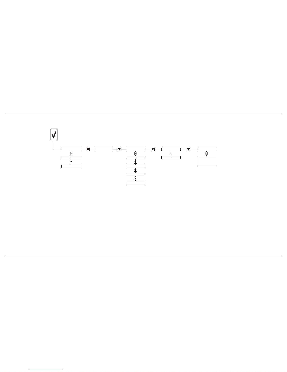
ConneX1 Operator’s Manual Appendix
57
Configuration Menu Structure
Appendix B Configuration Menu Structure
Bump test
Calibration
Calibration
Zero Sensor
Conguration
Operator
Location
User prole
Operation mode
Network
WiFi
Messages
Up to 10
predened
messages*
* Messages are user-congurable via FleetManager.
In FleetManager, open the Connex1 tab, and select
Message Conguration.
Page 66

ConneX1 Operating Operator’s Manual Appendix
58
Appendix C Review Mode Menu Structure
Sensor Details
Gas Exposures
Peak reading
TWA
Detector Details
Operation details
Device details
Distributor details
Date format
Time format
Measuring range
Low alarm setpoint
High alarm setpoint
TWA setpoint
STEL setpoint
Next cal date
Next bump test date
STEL
Reset readings
or
Messages
Received
Sent
Review Mode Menu Structure
Page 67

ConneX1 Operator’s Manual 59
Appendix D Datalog Information
The following information is recorded in a datalog
• Date and time
• TWA readings
• STEL readings
• Sensor readings
• Instrument status and sensor status flags
• Type of sensor installed
• Date of last successful calibration
• Date of last successful bump test
• Low alarm setpoint
• High alarm setpoint
• TWA alarm setpoint
• TWA interval
• STEL alarm setpoint
• STEL interval
• Calibration interval
• Bump test interval
• User configurations
• Operator Name
• Location Name
• Selected Profile
• Peripheral sensor readings
• Environmental data
Appendix E Event Log Information
The following events create an event log. Up to 60 event logs are stored. When
event log memory is full, the newer event logs overwrites the oldest event logs.
• Activation
• Deactivation
• Auto-power off (e.g. critical low battery alarm)
• Configuration change
• Battery status (e.g. low battery alarm)
• Calibration due ignored
• Bump test due ignored
• Low alarm acknowledge
• Date/Time change
• LocaXion Manager message received
• Replies to LocaXion Manager messages
• Location change
• Operator change
Datalog Information
Page 68

Page 69

Page 70

D6657/0
50104992-031
© 2012 BW Technologies by Honeywell. All Rights reserved.
 Loading...