


DSPXtra Encore
AUDIO PROCESSOR
USER MANUAL
www.bwbroadcast.com

Contents
1. The Encore Family
2. The DSPXtra-AM Encore
3. Warranty
4. Safety
5. Front & Rear Panels
6. User Interface
7. Installation & Operation
8. System Configuration
9. Presets Configuration
10. Menu Structure
11. Routing and Block Diagram
12. Technical Specification
!

1 - 1
About Encore 1
Welcome to the Encore family!
Encore is a modern, high-quality range of products designed around a common
hardware and software platform.
The Encore family includes:
§ Audio processors
§ RDS coders
§ Stereo generators
§ Rebroadcast receivers
§ Audio backup devices
§ Modulation analysers
§ …and is growing all the time!
Encore uses high-quality components, robust hardware and an innovative user
interface, which provides many benefits to broadcast technology users.
Modules and components are common to all products in the range – meaning ease of
service and minimal need to stock replacement parts.
For example, if you have an RDS coder, a modulation monitor and a backup audio
device, the same power supply, the same audio board and the same DSP board is used
in each one!
The rear panel is the same on every product. This means wiring can be standardised,
installation is simple and easy.
Front panels are consistent across the range – with OLED screens, LED displays, a scroll
knob and a few soft-keys, every products is easy to operate.
Encore has been designed to be very simple and intuitive to set up and operate –
everything is where you’d expect it to be and is easy to understand and use. Once
you’ve used one Encore product you can use them all!
The user interface is designed around the concept of ‘System’ and ‘Presets’ menus,
where the System menu is the same for every product and contains all the audio level
settings, the versatile and exclusive ‘Events and Alarms’ section as well the
communications, monitoring and telemetry system.

1 - 2
All product-specific settings are contained within the ‘Presets’ menu – providing an
automobile radio -like interface which works just as well for profiles in an RDS encoder as
it does for settings in an audio processor, a modulation monitor or rebroadcast receiver.
The web remote control interface is common across all products, as is the API and the
internal language, so it’s simple to interface the whole Encore range of products with
your common monitoring and telemetry system.
Every Encore product includes, as standard:
§ Backup audio
§ Events and Triggers –based Telemetry
§ Comprehensive communication section
§ Analogue and Digital audio interfaces
§ Ethernet, USB and RS232 connectivity
§ Interactive Web remote system
§ SNMP and TelNet support
A common hardware and software family of products, which are easy to set up, easy to
use, easy to maintain and easy to service.
Innovation, usability, quality, and confidence are what you get from Encore!

2 - 1
The DSPXtra-AM Encore 2
The BW Broadcast DSPXtra-AM Encore is the latest incarnation of the world famous BW
Broadcast range of DSP audio processors.
Using multi-band DSP technology, the DSPXtra-AM Encore offers a versatile and powerful
tool in creating a loud, punchy on-air presence.
The DSPXtra-AM Encore is driven by a fast 8-bit micro-controller which controls an array
of specialist analogue and digital circuits. These include 24-bit A/D and D/A converters,
analogue level circuitry, 6 x 24-bit DSPs, an Ethernet port, a GPIO port, an RS232 port, an
OLED screen and memory devices holding the software and firmware.
After input selection, the 24-bit digital audio signal is passed through conditioning
circuitry before being split into four bands by a phase matched crossover. Each band is
processed by an RMS leveler which corrects for input level variations and improves
consistency.
The audio is then split into six bands, which are further processed by intelligent audio
limiters. The subsequent distortion-cancelling clipping and filtering ensures your signal is
kept to a strict maximum while maintaining clear sound.
The easy to use front panel control system with OLED screen offers ease of use and
setup.
Comprehensive control of every processing parameter is available to the user both from
the front panel control system and by remote, web-based control.
At a fraction of the size, weight and price of its rivals, the DSPXtra-AM Encore is a small
but serious processor!

3 - 1
Warranty 3
Please ensure the warranty registration process is completed upon receipt of this product. To do so, go
to www.bwbroadcast.com/warranty with your product’s serial number to hand. BW Broadcast warrants
the mechanical and electronic components of this product to be free of defects in material and
workmanship for a period of up to ten years from the original date of purchase, in accordance with the
warranty regulations described below. If the product shows any defects within the specified limited
warranty period that are not due to normal wear and tear and/or improper handling by the user, BW
Broadcast shall, at its sole discretion, either repair or replace the product. If the warranty claim proves
to be justified, the product will be returned to the user. The freight will be paid by BW Broadcast within
the first 2 years, thereafter freight will be the responsibility of the customer. Warranty claims other than
those indicated above are expressly excluded.
Note: The warranty registration process must be carried out as described above to enable warranty
cover for 10 years. Otherwise, a 2-year warranty period applies.
Return authorisation number: To obtain warranty service, the buyer (or his authorised dealer) must
contact BW Broadcast during normal business hours BEFORE returning the product. All inquiries must be
accompanied by a description of the problem. BW Broadcast will then issue a return authorisation
number. Subsequently, the product must be returned in its original shipping carton, together with the
return authorisation number to the address indicated by BW Broadcast.
Warranty regulations: Any product deemed eligible for repair or replacement by BW Broadcast under
the terms of this warranty will be repaired or replaced within 30 days of receipt of the product at BW
Broadcast. If the product needs to be modified or adapted in order to comply with applicable
technical or safety standards on a national or local level, in any country which is not the country for
which the product was originally developed and manufactured, this modification/adaptation shall not
be considered a defect in materials or workmanship. The warranty does not cover any such
modification/adaptation, irrespective of whether it was carried out properly or not. Under the terms of
this warranty, BW Broadcast shall not be held responsible for any cost resulting from such a
modification/adaptation. Free inspections and maintenance/repair work are expressly excluded from
this warranty, in particular, if caused by improper handling of the product by the user. This also applies
to defects caused by normal wear and tear, in particular, of faders, potentiometers, keys/buttons and
similar parts. Damages/defects caused by the following conditions are not covered by this warranty:
Misuse, neglect or failure to operate the unit in compliance with the instructions given in BW Broadcast
user or service manuals. Connection or operation of the unit in any way that does not comply with the
technical or safety regulations applicable in the country where the product is used. Damages/defects
caused by force majeure or any other condition that is beyond the control of BW Broadcast. Any repair
or opening of the unit carried out by unauthorized personnel (user included) will void the warranty. If an
inspection of the product by BW Broadcast shows that the defect in question is not covered by the
warranty, the inspection costs are payable by the customer. Products that do not meet the terms of this
warranty will be repaired exclusively at the buyer’s expense. BW Broadcast will inform the buyer of any
such circumstance.
Warranty transferability: This warranty is extended exclusively to the original buyer (customer of retail
dealer) and is not transferable to anyone who may subsequently purchase this product. No other
person (retail dealer, etc.) shall be entitled to give any warranty promise on behalf of BW Broadcast.
Claims for damages: Failure of BW Broadcast to provide proper warranty service shall not entitle the
buyer to claim (consequential) damages. In no event shall the liability of BW Broadcast exceed the
invoiced value of the product.
Other warranty rights and national law: This warranty does not exclude or limit the buyer’s statutory
rights provided by national law, in particular, any such rights against the seller that arise from a legally
effective purchase contract. The warranty regulations mentioned herein are applicable unless they
constitute an infringement of national warranty law.

4 - 1
Safety 4
MAINS VOLTAGE: The Encore products operate from an AC power source between 110 and 240 V.
These power supplies use an IEC plug. The wiring format is:
Ground - GREEN/YELLOW
Neutral - BLUE
Live - BROWN
SWITCHED MODE POWER SUPPLY HAZARD Please note that the power supply unit in this equipment is of
the switched mode variety and has lethal voltages present internally. The switched mode supplies are
universal input fully approved type. They are non-serviceable modules and should be replaced if they
fail.
FUSES Only use fuses with the specified voltage and current ratings as stated on the back panel. Failure
to do so may increase the risk of equipment failure, shock and fire hazard.
TOXIC HAZARD This equipment may include R.F. components that may contain Beryllium oxide which is
a highly toxic substance that could be hazardous to health if inhaled or ingested. Care should be taken
when replacing or discarding such devices. Seek expert advice from the manufacturer should you
physically damage a device that contains Berillyium Oxide.
OTHER SAFETY CONSIDERATIONS Do not operate this equipment in the presence of flammable gases,
fumes or liquids Do not expose this equipment to rain or water.
CE CONFORMANCE This device complies with the requirements of the
1995/5/EC Radio and Telecommunications Terminal Equipment (R&TTE). The
equipment will meet or exceed the following standards: EN 60215:1996 (Safety
Requirements for Radio Transmitting Equipment), EN301489-11 (ERM/EMC for
Radio Equipment, Part 11 Specific Conditions for FM Transmitters), EN 302 0182 ERM (Transmitting Equipment for FM Radio Broadcasting service)
WEEE COMPLIANCE BW Broadcast Ltd is registered with Northern Compliance PCS
number WEE/P3438PR/ SCH and has been issued with WEE/FA0268RX as its unique
producer ID by the appropriate environment agency. BW Broadcast Ltd full comply
with it explicit responsibilities, subject to WEEE Collections Policy outlined in their
General Terms and Conditions of Sale, when it sells Electrical and Electronic
Equipment (EEE) to B2B customers in the UK and EU.
This appliance has been designed and manufactured with high quality materials
and components that can be recycled and reused.
Electronic appliances are liable to contain parts that are necessary in order for the system to work
properly but which can become a health and environmental hazard if they are not handled and
disposed of in the proper way. Consequently, please do not throw your inoperative appliance with the
household waste. Having purchased this appliance, it is your responsibility to dispose of this equipment
appropriately.
CAUTION: To reduce the risk of electrical shock, do not remove the cover. No user serviceable parts
inside. Refer servicing to qualified personnel.
WARNING: To reduce the risk of fire or electrical shock, do not expose this appliance to rain or moisture.
!

4 - 2
DETAILED SAFETY INSTRUCTIONS:
All the safety and operation instructions should be read before the appliance is operated.
Retain Instructions: The safety and operating instructions should be retained for future reference.
Heed Warnings: All warnings on the appliance and in the operating instructions should be adhered to.
Follow instructions: All operation and user instructions should be followed.
Water and Moisture: The appliance should not be used near water (e.g. near a bathtub, washbowl,
kitchen sink, laundry tub, in a wet basement, or near a swimming pool etc.). The appliance should not
be exposed to dripping or splashing and objects filled with liquids should not be placed on the appliance.
Ventilation: The appliance should be situated so that its location or position does not interfere with its
proper ventilation. For example, the appliance should not be situated on a bed, sofa, rug, or similar
surface that may block the ventilation openings, or placed in a built-in installation, such as a bookcase
or cabinet that may impede the flow of air through the ventilation openings.
Heat: The appliance should be situated away from heat sources such as radiators, heat registers, stoves,
or other appliance (including amplifiers) that produce heat.
Power Source: The appliance should be connected to a power supply only of the type de- scribed in the
operating instructions or as marked on the appliance.
Grounding or Polarisation: Precautions should be taken so that the grounding or polarisation means of
an appliance is not defeated.
Power-Cord Protection: Power supply cords should be routed so that they are not likely to be walked on
or pinched by items placed upon or against them, paying particular attention to cords and plugs,
convenience receptacles and the point where they exit from the appliance.
Cleaning: The appliance should be cleaned only as recommended by the manufacturer. Wash your
hands.
Non-use Periods: The power cord of the appliance should be unplugged from the outlet when left unused
for a long period of time.
Object and Liquid Entry: Care should be taken so that objects do not fall and liquids are not spilled into
the enclosure through openings.
Damage Requiring Service: The appliance should be serviced by qualified service personnel when:
§ The power supply cord or the plug has been damaged;
§ Objects have fallen, or liquid has been spilled into the appliance;
§ The appliance has been exposed to rain;
§ The appliance does not appear to operate normally or exhibits a marked change in
performance;
§ The appliance has been dropped, or the enclosure damaged.
Servicing: The user should not attempt to service the appliance beyond that is described in the Operating
Instructions. All other servicing should be referred to qualified service personnel.

5 - 1
Front & Rear Panels 5
The Encore range uses several versions of the front panel, each using similar components
and featuring the same method of operation.
!
Multicolour LED
matrixes for level
displays
OLED displays for
menu system and
analysis
Scroll knob, LED ring and
buttons for control and
setup
Headphon e
output for high
quality audio
monitoring

5 - 2
Note: Some connectors on the rear panel are non-functional where appropriate to the
product.
Analog audio
inputs
Pin 1 0v
Pin 2 + (hot)
Pin 3 – (cold)
Analog
audio
outputs
Pin 1 0v
Pin 2 + (hot)
Pin 3 – (cold)
MPX
inputs
and
outputs
(BNC)
Antenna
inputs
(BNC)
AES/EBU Digital
input and output
Pin 1 0v
Pin 2 + (hot)
Pin 3 – (cold)
USB
and
Ethernet
(LAN)
Events &
Triggers
Mains power
(IEC)
90-260v AC, 25w
RS232

6-1
User Interface 6
6
NAVIGATING
The Encore products have an intuitive interface based around a pushable scroll knob,
surrounded by a ring of LEDs, with a series of buttons. Some products have three buttons,
some five and some six.
The buttons can be ‘soft keys’, and perform various functions denoted by icons shown
adjacent to them in the displays, or may be function-specific - in which case the buttons
are illuminated with the following symbols:
ONLINE
OFFLINE
DECODE
ENCODE
INPUT 1
INPUT 2
Audio is passing through the unit and is being
processed.
Input is connected to output and audio is not being
processed.
The unit is operating as a stereo generator, or
encoder, producing a composite (MPX) output
signal from the analog or digital inputs!
The unit is operating as a stereo decoder,
producing discrete left and right, analog and
digital outputs from a composite signal input.!
Switches the unit to tuner 1 or MPX input 1.!
Switches the unit to tuner 2 or MPX input 2.!

6-2
The icons that can be shown against the softkeys are as follows:
If the ‘scroll screen left’ or ‘right’ icons are displayed, this indicates that there are
additional screens available. Pressing these buttons slides the displays to and
from these other screens.
‘Back’ will move back up one step in a menu tree.
‘Undo’ and ‘redo’ are typically used in an audio processor to perform an
‘A/B comparison’ between two presets, or between a modified and an
unmodified preset.
The ‘headphone’ button, when pressed, will cause the icon to flash indicating
that the headphone level may be directly adjusted by rotating the scroll knob
(rather than having to enter the System | Audio menu as described in Section 8).
This mode will time out after 5 seconds of inactivity, or when the button is pressed
again.
The ‘delete text’ and ‘accept text’ buttons are used when the virtual ‘qwerty’
keyboard is being employed to add or modify text, perhaps to name a preset or
to enter other alpha-numeric strings such as email addresses etc.
While navigating the menus, if an ‘info’ help-text is available for that parameter,
the ‘i’ symbol will illuminate next to a softkey. Pressing this softkey will show the
information; pressing it again (or pressing ‘back’) will dismiss the info.
The Encore’s high-quality OLED displays show various levels and parameters, plus allow
selection and editing of the various settings throughout the unit.
The menu system is navigated by rotating the knob to highlight an item and pushing it to
open a submenu, or to select the parameter for editing.
While in a submenu, pressing the ‘back’ softkey will return to the parent menu.

6-3
EDITING A PARAMETER
To edit a parameter, navigate to it in the menu using the knob - square brackets [ … ]
will surround the currently highlighted parameter. Press the knob to select the
parameter, then rotate the knob to change it.
Changes happen immediately as you turn the knob; press the knob again to keep the
change; alternatively press the ‘back’ softkey to revert without changing.
The parameter setting will be shown on the OLED screen, numerically and with a
progress bar, as shown below:
EDITING A TEXT FIELD
When editing a text field, such as the system name or a preset name, a ‘qwerty’
keyboard will be shown on the OLED display.
Highlight the letter to be used by turning the knob and press to select. To delete a letter,
use the softkey adjacent to the ‘X’ icon .
To switch to a numerical keyboard, select the ‘123’ button with the scroll knob and press
to select.
To accept and save the new text, press the softkey indicated by the ‘check' icon .
7 - 1
Installation & Operation 7
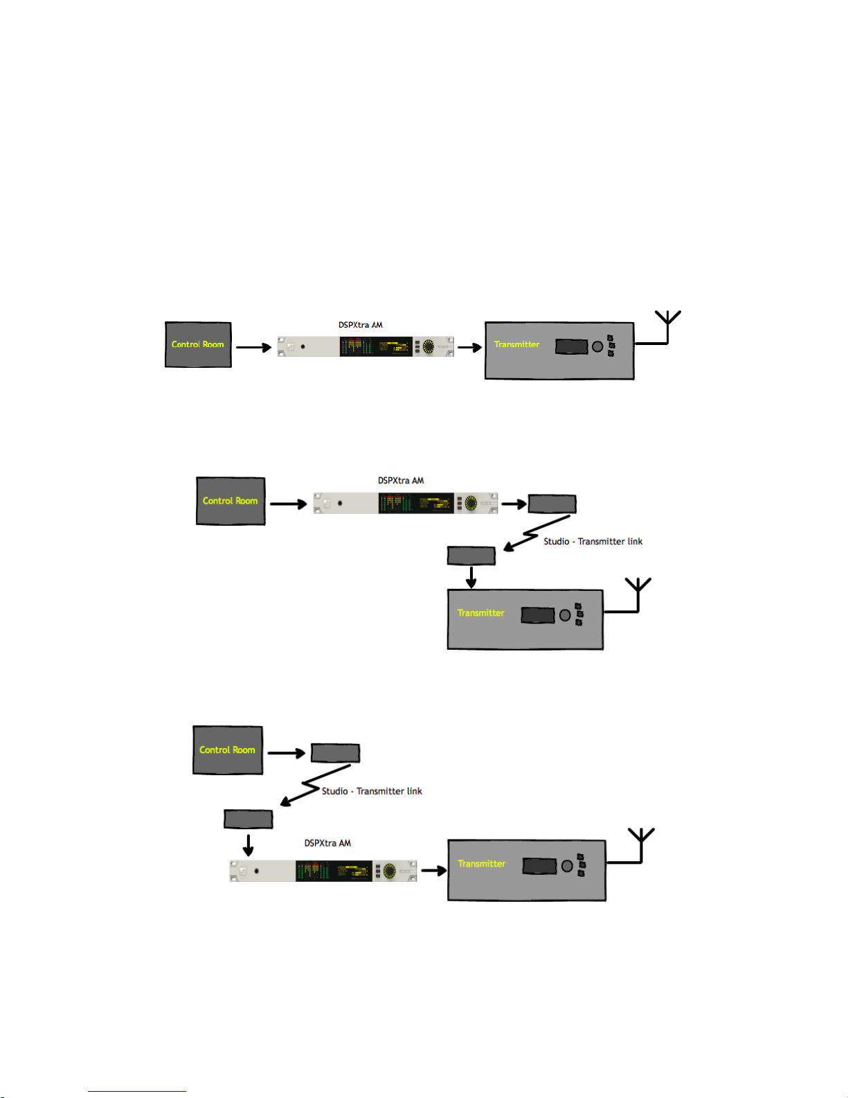
The DSPXtra-AM Encore can be installed in a number of ways, for example:
§ At a combined studio/transmitter site;
§ At a studio location before a studio-transmitter link;
§ At a transmitter site, fed from a studio-transmitter link;

7 - 2
7.1 QUICK SETUP
Install the DSPXtra-AM Encore into the rack; The unit should be mounted in a grounded,
19” (483mm) equipment rack. While the DSPXtra-AM Encore generates little heat itself, it
could be damaged by being confined between other heat-generating equipment. If
the equipment directly below or above the DSPXtra-AM Encore runs hot, you should
allow one single rack space between them.
The area directly to the rear and sides of the unit should be open, to allow free-flowing
air, and the environment should be as dust-free as possible.
1. Connect AC power to the unit;
2. Connect the analogue or digital output;
3. Select analogue or digital input as the source of processing with the ‘input’ item in
the ‘system|audio i/o’ menu;
4. Navigate to the System | Audio i/o | Outputs menu, and adjust the low-pass filter
setting as required. This will affect the occupied bandwidth of the AM
transmission.
5. You can use the built-in tone generator to set the output levels. Set the output
source in System | Audio i/o | Outputs to ‘tone’, set Amplitude to 60%, then adjust
the output level until your transmitter (or modulation monitor) reads 50%
modulation (the 10% difference is to account for possible overshoots in the
transmitter).
6. Navigate to the System | Audio i/o | Inputs menu, and adjust the high-pass filter
setting.
7. Navigate to ‘presets’, and select a preset from the list.
That’s it - You’re on the air!
Further information on each parameter is contained in section 9 ‘Presets Configuration’
in this manual.
7.1.1 AUDIO CONNECTIONS
The analog audio inputs and outputs are balanced XLR connectors (pin 2 +ve) and can
range from peak levels of -10dBu to +24dBu. The menus in the DSPXtra-AM Encore will be
used to calibrate the audio levels to suit your facility.
The digital inputs and outputs are AES/EBU compliant, and will also reliably handle S/PDIF
with suitable cable adaptors. A built-in sample rate converter will convert whatever the
incoming audio’s sample rate is to the preferred output rate, if desired. This selection is
made in the system|audio i/o menu.

7 - 3
7.1.2 DATA AND GPIO CONNECTIONS
The DB-9 ‘GPIO’ connector is used for preset switching and/or to interface with other
remote control equipment or telemetry.
The RJ-45 Ethernet connector allows the DSPXtra-AM Encore to be controlled over a
network using the built-in web interface. TCP/IP network settings are contained in the
system|communications menu.
7.2 THE DISPLAYS
When the DSPXtra-AM Encore is powered up, the OLED screen will show the ‘home
screen’:
The three buttons available on the home screen are ‘system’, ‘sleep’ and ‘presets’.
The ‘system’ and ‘presets’ menus are described sections 7 and 8 of this manuscript.
The ‘sleep’ button will, when highlighted and pressed, apply an instant ‘screensaver’
function in which both screens are extinguished and a ‘heartbeat’ is played on the
knob’s LED ring to show at a glance that the unit is powered up.
The ‘sleep’ state will also be automatically entered if no front panel controls are
operated for 30 minutes.
[‘sleep’ will be replaced in an imminent firmware version by ‘lock’ – which will manually
put the unit into the ‘security lock’ state - an added feature in that version].
7.2.1 METERING
In addition, input and output levels, as well as processing operation is displayed on a
high-quality LED matrix.
7.2.2 INPUT/OUTPUT METERS
The input meters show the level of the input audio. The meters are ‘hooked into’ the DSP
code after the input source selection.
The output meters represent the level in dB below full scale output. This output level is the
peak output level of the processing and has nothing to do with the actual output level
set by the analogue and digital output level options.

7 - 4
The output meters show a smaller dynamic range than the input meters; this reflects the
smaller dynamic range of the audio once processed by the DSPXtra-AM Encore.
The I/O meters follow an approximation of the PPM levels of the audio waveform.
7.2.3 MULTIBAND AGC
The first four meters show the gain reduction of the multiband AGC.
There is one meter per stereo channel, and the value is that of the largest gain reduction
of either left or right channels. Due to this you may see strange results if the L/R input
channels are not well balanced in level.
7.2.4 MULTIBAND LIMITER
The second six gain reduction meters show the gain reduction of the multiband limiter.
There is one meter per stereo channel – the above caveat applies here, too.

THE SYSTEM MENU
This menu contains all the fundamental unit configuration settings, and should be the first
place you go after taking the Encore out of its box!
These settings are peculiar to the installation, perhaps the transmitter site itself, as
opposed to the following ‘Presets’ section (Section 9) which are particular to the exact
usage and model of the unit.
Power the unit up, and from the home screen, highlight and press the ‘system’ button:
You’ll now see a list of submenus:
Audio i/o: Contains all audio input and output settings, as well as output
routing selections.
(Not present in all Encore products)
MPX generator: Settings for the mpx (‘composite’) generator.
(Not present in all Encore products)
Events: A comprehensive events/alarms/scheduling system.
Time: Manually setting the unit time and date, or automatically setting
this via ntp.
Users: Set up admin user and standard users.
Communication: A sub menu containing settings for identity, ethernet,
email, web remote, snmp, telnet, logging and RS232.
About: Unit information and power supply status.
Note: Certain menu items will be different or not present in some products, as
appropriate to their features.
Let’s take some time to discuss the contents of each of these menus:

8.1 AUDIO I/O
(Certain menu items are omitted in some products in the Encore range).
Within this there are two submenus – ‘inputs’ and ‘outputs’.
‘Inputs’ allows you to set the operating level of the unit when referenced to the rest of
your installation. For both analog and digital reference level, please set these to your
maximum normal operating level.
For example, if you will be feeding analog audio into the unit that may reach but never
exceed +12dBu, set the ‘analog ref level’ to +12. (For PPM users, PPM4=+4, PPM5=+8,
PPM6=+12).
Similarly, if your digital levels may meet but not exceed -10dBFS, set ‘dig ref level’ to -10.
‘Outputs’ allows you to set output levels from each physical output, and choose what
source feeds those outputs.
The sections of this submenu are:
An (analog) output source: none
analog audio
digital audio
tuner 1 audio
tuner 2 audio
test tone (a 1kHz sine wave)
diversity
Analog output level: -18dBu to +24dBu
Dig (digital) output source: none
analog audio
digital audio
tuner 1 audio
tuner 2 audio
test tone
diversity
Dig output level: -20dBFS to 0dBFS
Dig output sample rate: 48kHz
96kHz
192kHz
MPX 1 source: none
mpx in 1*
tuner 2 mpx*
mpx generator
pilot tone
rds
MPX 1 out level: 0dBu to +12dBu**

MPX 2 source: none
mpx in 1*
tuner 1 mpx*
tuner 2 mpx*
mpx generator
pilot tone
rds
MPX 2 out level: 0dBu to +12dBu**
Headphones source: none
analog audio
digital audio
tuner 1 audio
tuner 2 audio
test tone
diversity
Headphone level: 0 to 100%
For convenience, the headphone source and headphone level settings are duplicated
directly under the ‘audio i/o’ menu.
* Note that if ‘tuner 1(or 2) mpx’, or ‘mpx in 1’ is selected as the source for an mpx
output, the received signal merely passes through the unit, unaffected by the ‘fmsi’
signal processing (please see section 9 of this manual).
** The mpx output level adjustments only affect the output of the internal mpx
generator. If the mpx (1 or 2) output source is set to ‘tuner 1 (or 2) mpx’, the output level
is fixed at +6dBu.
8.2 MPX GENERATOR
(Not present in all Encore products)
This menu controls the on-board stereo generator (‘MPX’ meaning multiplex, sometimes
known as ‘composite’).
The stereo generator includes a composite clipper. With a drive level of 0dB, this has no
effect; above that it will become active and clip the MPX signal. The clipper contains
RDS/SCA protection filters, also there is a pilot protection filter option.
The audio clipper protects the MPX generator from peak excursions and overshoots in
the source audio. It is distortion-cancelling and anti-aliased.
Furthermore, there is an ‘overshoot compensator’ which handles any overshoots from
the main clipper, and restricts the audio bandwidth to 15kHz.
The MPX generator menu contains the following parameters:

Source: none
analog audio
digital audio
tuner 1 audio
tuner 2 audio
diversity
test tone
Preemphasis: 50uS, 75uS, off.
Pilot level: 0 to 12% in 0.1% increments
RDS level: 0 to 5% in 0.1% increments
Audio clip drive 0 to 12
O-sh compensate drv -3 to 9
(overshoot compensation drive)
Comp (composite) clipper drive: -0.5 to 2
Pilot protection no / yes
8.3 EVENTS
This is a very comprehensive monitoring, events and alarms section. It allows changes to
be made to the configuration of the Encore unit resulting from external sources via the
Events and Triggers port, or from conditions detected from incoming signals – be they via
the tuners or the audio inputs.
It is really a telemetry system in itself. As events can be triggered from external sources,
you can use it to monitor other equipment in your facility, even door-open sensors,
intruder alarms, in fact anything that can pull one of the four input pins to 0v.
The system is designed in a very intuitive, conversational way. “When this happens, for
this long, do these things. Then when it’s stopped for this long, do that.”
In the ‘events’ menu, the first sub-menu is ‘GPO pin config’. In this section, with the
‘mode’ parameter, you can determine what each of the four GPO pins do:
1. Switch as an event action (see later);
2. Track tuner 1 signal strength;
3. Track tuner 2 signal strength;
4. Track analog input level;
5. Track digital input level.
6. Track unit temperature.
With option 1, the pin is a ‘digital’ output (i.e. either ‘on’ or ‘off’). With options 2 through
6, the pins act in an analog manner, outputting 0 – 5v which will track whatever signal
you have selected.

The other option available in this menu is ‘polarity’ – where you can set each pin to
output either active Hi-Z (high impedance) or active low (i.e. connected to 0v).
The Events and Triggers port pinouts are:
Next is the list of the 8 available events, each of which can perform a variety of actions
when triggered.
Please highlight and select one of the events.
To set up an event:
1. For now, leave the ‘active’ setting ‘off’.
2. Select from the list what you want to ‘trigger’ the event; the choices are tuner
signal strengths, tuner audio levels, analog and digital inputs and outputs, unit
temperature and the status of the GPI pins.
3. Then select what ‘condition’ should cause the trigger – more than, less than
or in some cases equal to or not equal to.
4. Next, set the ‘value’ – the range here varies according to the trigger type.
5. Next is the time to wait after triggering before the event is activated (for
example, wait for 15 seconds of silence before activating the event).
6. ‘revert’ determines what happens when the trigger condition ends – does the
unit go back to its previous condition, and if it does, is it immediate or delayed?
7. Next you can set this revert delay.
The next parameters set what actions the event causes. You can set it to do any or all of
the following:
load a different preset;
change tuner frequencies;
change various output sources;
switch one of the GPO pins;
send an email;
send an snmp trap message.
Note that if you select ‘load preset’ as an action, the ‘revert’ function is greyed out and
not available. This is because a change of preset can involve a change of frequency of

both tuners, so in this case there’s no way the Encore can know when or if the event
trigger has ended.
When you’re happy with the event setup, return to the top of the event menu, and
switch it to ‘active’.
Exit from the ‘events’ menu by repeatedly pressing ‘back’ until you reach the home
screen.
8.4 TIME
This menu allows you to set the unit’s time and date, or if it has network access to an ntp
server, to use that.
The following parameters can be accessed:
uptime: A display of the time, in hours, minutes and seconds that the
Encore has been powered up.
time: Allows manual setting of date and time.
ntp: off / on (whether to use ntp or not)
update now: ‘run’ – pressing this forces an immediate update of system
time via the ntp server.
host: the ntp hostname, e.g pool.ntp.org or an IP address.
period: How often an ntp time update occurs – every 1hr, 12hrs or
24hrs.
8.5 USERS
This menu allows you to define parameters for people who will have access to the
Encore unit, and who will be able to log in via the web remote.
There are four users available:
admin A ‘power-user’ who is able to edit/change settings as well
as view all screens;
user 1, 2, 3 These users can be limited to either merely viewing settings and
screens, or controlling them in the same way the admin user can.
However, a non-admin user with ‘control’ privilege cannot add or
change any other user’s details.
Within the users menu, you are able (if you’re an admin) to set the users’ password, their
email addresses and their privileges.

[In an imminent firmware release, ‘security’ will be implemented which will utilise these
settings more comprehensively].
8.6 COMMUNICATION
This menu contains the following submenus:
Identity: Allows a unit name, site number and lat/long (‘GPS position’) to be
set. This is useful when managing multiple units via the web
interface, and when receiving emails from the ‘events’ section, so
it’s obvious where the email came from.
Ethernet: Allows you to set the following parameters, relevant to the IP
network the Encore is connected to:
DHCP: ‘on’ if your network has a DHCP server from which the Encore
will be able to derive network parameters automatically; set to
‘no’ to define these settings manually.
DNS: ‘on’ to use the dns server derived above, or ‘off’ to manually enter
a DNS server.
IP: Manually enter he unit’s IP number.
Subnet mask: Manually enter the unit’s subnet mask appropriate to your
network.
Gateway: Manually enter the gateway IP number (usually the IP number
of your router).
DNS 1: Manually define one DNS server IP number.
DNS 2: Manually define an alternate DNS server.
MAC: A display of the unit’s mac address
Link: Shows ‘up’ if the unit’s ethernet connectivity is working, ‘down’ if
not.
Email: Allows you to set up the email communication of the
Encore:
Sender: the email address of the Encore, e.g encore-
01@stationname.com
Mail method: ‘BW’ to allow the unit to send emails via the BW Broadcast
monitoring system; ‘SMTP’ if you wish to send the
emails via your own SMTP server;

(if ‘SMTP’ is selected, further settings will appear allowing you to specify
the name of this server, it’s authentication method and if necessary the
SMTP password).
Test: This submenu allows you to send a test email to one of the
users (previously defined in 7.1.5 ‘Users’ in this manual).
Web remote: Here you can turn on or off access to the Encore
by the ‘Encore web remote’ software, and to define the
port that this web remote will use – default is the common
http port 80.
SNMP: Settings for using Simple Network Management Protocol, to
allow the Encore to communicate with other
telemetry and monitoring systems.
The SNMP ‘MIB’ file is accessible when the unit
has an ethernet connection, by navigating to http://[unit
IP]/Encore.mib
Telnet: Set Telnet access on or off, and define the port.
Logging: Sets up a UDP connection to an external logging server,
and/or log to file o via a serial connection.
RS232: Enable/disable the rear-panel RS232 (serial) connector, and
sets the baudrate to be used.
8.7 ABOUT
A display of unit details, serial number, hardware and software versions etc. This
information may be requested by a BW Broadcast support technician if you need live
assistance. The OLED ‘sleep’ timeout is also set here.
RESTART AND FACTORY RESET
There is also a ‘restart’ and a ‘reset to defaults’ command in this menu. Beware – ‘reset
to defaults’ will remove any settings you have modified in Presets, and everything you
have entered in System.
…which includes the Ethernet settings – so this isn’t a good thing to do if you’re
connected remotely, as you may lose IP connectivity.
STATUS
This submenu shows values of current hardware parameters:
PSU voltage; PSU current; PSU power; fan voltage; fan state; temperature; plus fan speed
control – which should be left set to ‘auto’ unless otherwise advised by a BW Broadcast
support technician.

9 - 1
Presets Configuration 9
9.1 THE PRESETS MENU
The DSPXtra-AM Encore features 20 factory presets, and up to 10 user presets.
The factory presets can be used as a starting point in creating your own customised user
preset.
The presets are accessed as follows:
From the home screen, highlight the ‘presets’ button, and press the knob.
You will be presented with the following screen:
This shows the list of presets – those prefixed with the letter F are factory presets, the prefix
U indicates a user preset location.
The rest of the preset locations will become visible if you scroll down the list.
To the left of each preset name is the ‘status block’.
The current preset is shown highlighted – if you scroll away from this, the status block to
the left of the preset name remains filled to indicate that this is the preset that is currently
loaded.
If this block shows the letter A, this indicates that the preset has been selected by an
‘action’ from the ‘events’ section of the DSPXtra-AM Encore (see section 8 in this
manual).
If the block shows the letter S, the preset has been selected by a ‘schedule’ event.
If a preset has been edited but not saved, an asterisk * is shown in this block.
If multiple statuses are active, the priority is: A, S, *, .

9 - 2
In addition, in this screen, softkey 2 shows the i symbol. Pressing this will display extra
information about the highlighted preset, such as and date/time the preset was created
and last used.
The factory presets cannot be overwritten, however they may be used as good starting
points for you to create your own presets, which can then be saved in one of the user
preset locations.
The factory presets are:
F1 Bypass
F2 General
F3 General bright
F4 General heavy bright
F5 Talk
F6 Talk bright
F7 Talk heavy
F8 Talk heavy bright
F9 News
F10 News bright
F11 Sports
F12 Sports bright
F13 Music
F14 Music open
F15 Music open bright
F16 Music bright
F17 Loud
F18 Loud bright
F19 Classical-jazz
F20 Classic-jazz bright
The ‘bright’ versions of each preset will trade off some loudness while accentuating the
high frequencies.
9.1.1 LOADING A PRESET
To load a preset, scroll to it using the knob, when your desired preset is highlighted, press
softkey 3 – which you may have noticed is now displaying a ‘check’ icon .
Or you can scroll to the preset and press the knob – this will load the preset and enter
preset edit mode.
9.1.2 EDITING A PRESET
To edit a preset, scroll to it and press the knob. This action will load the preset too – as the
configuration is actually edited ‘live’.
As soon as a preset is modified, an asterisk * appears in the status block, and softkey 3
displays the undo icon .
An asterisk will also be shown in the top line of the edit screens as soon as any
modification is made, to remind you that the preset is in a modified state.

9 - 3
Pressing the ‘undo’ button will revert the preset (and therefore the live state of the
DSPXtra-AM Encore) to its unmodified and saved state. Once pressed, the ‘redo’
icon is shown against softkey 3. Guess what happens if you press it!
If you attempt to exit the preset edit menu and load another preset before saving your
changes, a warning dialog box will appear, informing you that if you continue, your
changes will be lost, and asking if you wish to continue, or go back to save your
modified preset.
Preset name: Selecting this brings up a ‘qwerty’ keyboard, so that an optional
friendly name can be appended to the default preset name, which is U1,
for example. The first part of the preset name is always the preset number.
Save to: Allows the settings contained within the current preset to be saved back
to itself (not if it’s a factory preset) or to any other user preset slot.
Note: If you try to save to a preset slot other than the one you’ve modified, a pop-up will
warn you that you are about to overwrite the contents of that preset, and asking you if
you’re OK with that.
The factory presets present a useful starting point – you can quite happily get your
DSPXtra-AM Encore on the air using one.
However, you may become emboldened enough to want to modify the presets and
tailor the sound exactly how you’d like.
With this in mind, a digression into the finer points and the raison d'être of audio
processing is probably useful at this stage.
So let’s do it!
!

9 - 4
9.2 INTRODUCTION TO AUDIO PROCESSING
Most audio processors use a combination of compression, limiting and clipping to
'funnel' the dynamic range down, reducing the peak to average ratio in each stage. A
cascaded arrangement of compressor, limiter and clipper produces the best results. The
first stage of processing usually operates in a slow manner, the processing getting
progressively faster and more aggressive as the audio passes through the chain. The
instantaneous peak clipper or look-ahead limiter is the final stage of the chain and sets
the final peak level.
The images below illustrate a section of audio as it passes through a typical audio
processor.
Img. 1
Image 1 shows an unprocessed section of audio.
The images that follow represent compression of the input waveform, followed by
limiting, and then finally peak clipping.
9.2.1 COMPRESSION
Img. 2
Compression reduces the dynamic range of the audio waveform slowly in a manner
similar to a trained operator riding the gain. Compression is usually performed on the
RMS level of the audio waveform and the ratio of compression is usually adjustable.
Compression is usually gated to prevent gain riding and ‘suck-up’ of noise during silence
or quiet periods. You can see the results of this in image 2.
9.2.2 LIMITING
Img. 3
Limiting is a quicker form of compression that employs faster time constants and higher
ratios to produce a denser sound while controlling peaks - based upon the peak level of
the audio waveform. Excessive limiting can create a busier packed ‘wall of sound’
effect. Image 3 shows the effects of limiting on our audio sample.

9 - 5
9.2.3 CLIPPING
Img. 4
Clipping the audio waveform will not produce any audible side effects if performed in
moderation. Excessive clipping however, will produce a form of distortion that is
unpleasant to hear. Clipping can also be used as an effective method of high
frequency peak control when used in conjunction with distortion controlling filtering. See
image 4.
9.2.4 LOOK-AHEAD LIMITING
Often used instead of a clipper in systems that feed bit rate reducing audio codecs,
look-ahead limiting examines the audio waveform and prepares a gain control signal in
advance of the delayed audio waveform arriving. This prevents overshoots while
minimising distortion. A look-ahead limiter behaves in the same way as a soft clipper.
Competent look-ahead limiters will usually be of the multi-band variety.
9.2.5 SOURCE MATERIAL QUALITY
The DSPXtra-AM Encore has the ability to substantially improve the quality of your
broadcast. However the DSPXtra-AM Encore can only work with what you provide it. The
best performance will be obtained when the DSPXtra-AM Encore is fed with very clean
source material. After dynamic multi-band re-equalisation is performed, poor quality
source material will sound poorer when processed with the DSPXtra-AM Encore.
We strongly advise against the use of MP3s and other compressed audio formats for
audio storage. If you must use compressed audio, we advise bitrates of at least 256
Kbps. Linear formats are always to be preferred. Compressed audio formats employ
frequency masking data reduction techniques to reduce the bitrate. Through reequalisation the DSPXtra-AM Encore can violate the frequency masking characteristics
of the bit reduction process, creating distortion that was inaudible prior to the DSPXtraAM Encore processing.
9.2.6 HF BOOST (PRE-EMPHASIS)
Today’s typical AM receivers have narrow bandwidth (typically 3 kHz) and it is usually
beneficial to compensate for the high-end roll-off by boosting the high frequencies in
the processor. This can help restore some of the high-end response and brightness. The
DSPXtra-AM Encore has an HF equalizer that can provide as much as 20 dB of high end
boost. The graph below illustrates pre-emphasis curves in 2 dB steps. The blue curves
show the response with the shape control set to 1, and the red ones show the response
with the shape control set to 10.
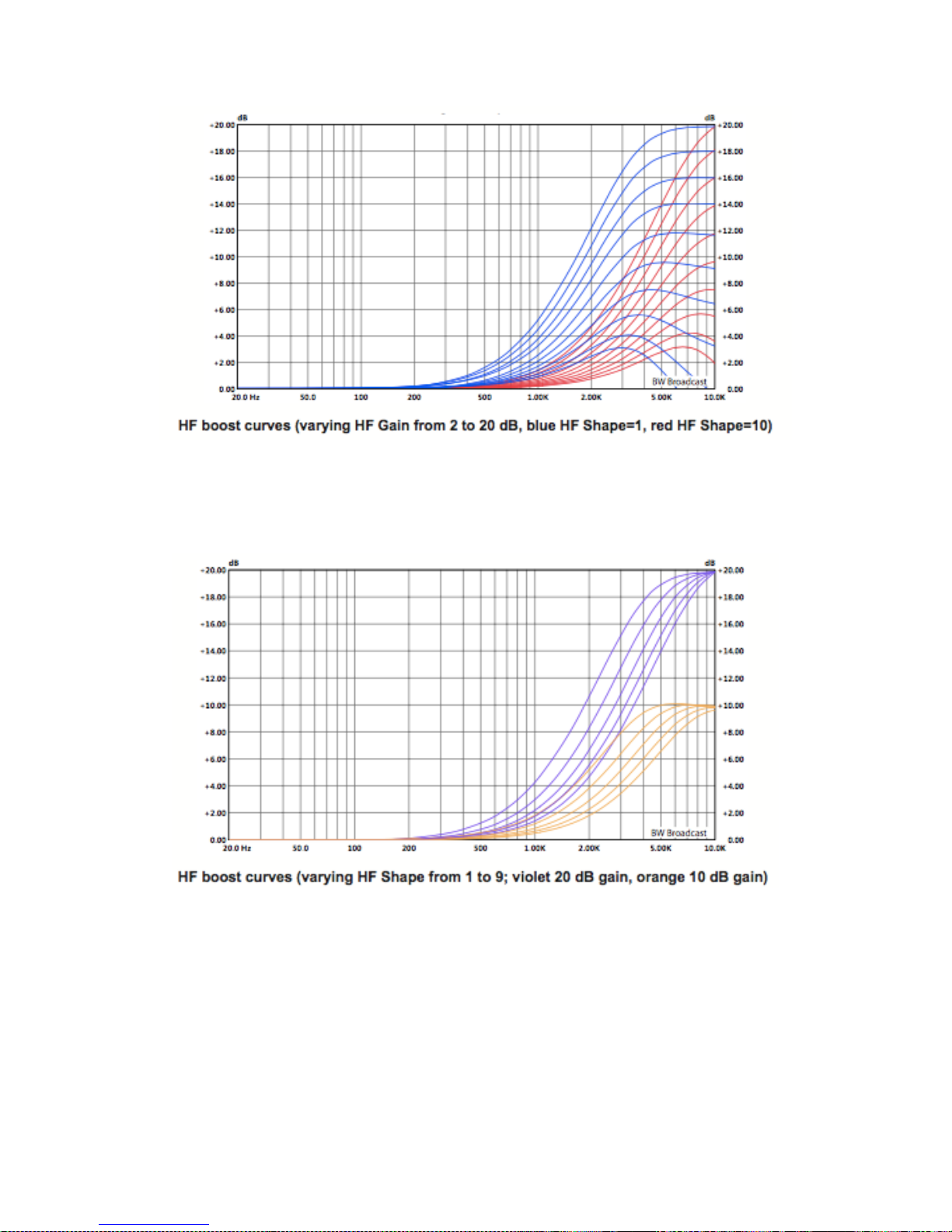
9 - 6
The HF curve can be shifted slightly lower or higher in frequency, with a shape control.
Illustrated below are curves at 10 dB and 20 dB gain, with the HF shape control varied
from 1 to 9 in steps of 2. To provide NRSC-1 pre-emphasis, the HF Gain should be set to 10
dB and the HF Shape to 8.
9.2.7 LOW PASS FILTERING
To accommodate various bandwidth limitation requirements in different countries, the
DSPXtra-AM Encore has an adjustable low pass filter. The filter is adjustable from 4 kHz to
10 kHz in 500 Hz steps. Out of band spectrum is reduced by more than 100dB. The filter
frequency roughly corresponds with the -18dB attenuation point (this was chosen so that
the numbers more meaningfully relate to the AM masks). For example, setting of 9kHz
means that the response is 18dB down at 9kHz. Slight exemption to this rule are 4.5kHz
and 8.5kHz curves which have been optimised to maximize audio bandwidth under
NRSC-1 standards. To comply with the NRSC-1 standards (10kHz bandwidth for analog
AM, 8kHz bandwidth for Hybrid AM IBOC or 5kHz bandwidth for Hybrid AM IBOC

9 - 7
transmission) set the filter to 10kHz, 8.5kHz and 4.5kHz respectively. The graph below
shows all the low pass filter curves. You can use it to determine the correct setting for the
required bandwidth (or mask) in your country.
!

9 - 8
9.3 THE PROCESSING STRUCTURE
The DSPXtra-AM Encore broadcast audio processor is intended to be used for processing
audio prior to broadcast on AM.
9.3.1 THE PROCESSING PATH
Input selection and conditioning
The DSPXtra-AM Encore offers the user input selection, gain control and a selection from
a range of stereo/mono options. The audio is then routed through high and low pass
filters.A silence detector provides automatic primary to secondary input failure
switching.
Bass enhancement
The DSPXtra-AM Encore offers a bass enhancement via peaking filter that can be set to
provide up to 6dB of gain on one of four frequencies with a choice of Q's. This can be
thought of as a simple bass parametric.
Crossover
The DSPXtra-AM Encore employs linear-phase time aligned digital FIR filtering to split the
audio spectrum into 4 bands before the AGC, and again into 6 bands before the
limiters, while maintaining sonic transparency.
Multi-band AGC
Like the wideband AGC the DSPXtra-AM Encore processes each band with RMS based
levellers. Each bands gain control processing function can be configured in different
manners to provide different effects. Adjustable timings, band couplings and complex
gating features afford the user with full control of this important re-equalisation stage of
the processor.
Multi-band Limiters
Each band has its own dynamic peak limiter. Multiple time constant based detectors
with built in adjustable hold and delay functions significantly reduce distortion.
Mixer
The six bands are 'virtually' mixed together at this stage. In truth, the six bands have
become three.
Distortion controlled clippers
The DSPXtra-AM Encore clipping algorithms peak limit (clip) and linear phase filter the
audio in three bands for maximum distortion control before being fed to the final clipper
stages. The clippers in the DSPX have an adjustable asymmetry and can produce up to
150% positive peak modulation if desired, while maintaining the negative peak
modulation at 100%.

9 - 9
Output selection, processing and routing
The AM output has an adjustable low-pass filter to comply with NRSC or ITU-R standards,
tilt equalization to compensate for a non-DC path in the transmitter and a tone
generator to facilitate set-up and alignment.
A quiet word about the final peak limiting stage:
This stage employs distortion controlled clippers to limit the peaks of the signal. Distortion
controlled clipping is the best method for preserving as much high frequency energy as
possible, important when the high frequency loss characteristics of the AM broadcast
receivers is taken into account.
Distortion controlled clipping produces harmonic distortion which if used moderately
can produce a sizzling bright sound but can result in a ripping or tearing sound if used
excessively – so be careful!
!

9 - 10
9.4 SETTING UP THE PROCESSING
Each preset menu allows access to all of the processing blocks that make up the
DSPXtra-AM Encore. There are further sub-menus inside each ‘preset’ menu.
The submenus follow the signal path through the DSPXtra-AM Encore, as shown in the
block diagram above.
'HIGH PASS FILTER' This parameter allows you to select from a variety of high pass filters.
You can select from 20 Hz, 30 Hz, 40 Hz, 50 Hz and 60 Hz. You also have the ability to
bypass the high pass filter with the 'OFF option. The high pass filter can be used to
reduce rumble or can be effective in removing low frequency energy that most AM
receivers can't reproduce. We suggest you set the high pass filter to 30 Hz.
The 'EQ' section contains the low frequency enhancement filters which are used to
provide bass enhancement and high frequency equalizer to provide high-end boost
(pre-emphasis).
‘PEAKING BASS EQUALIZER’ A pseudo parametric style bass equalizer control that allows
you to sweet tune the bass. Four frequencies, amplitudes and Q's are provided giving
you 6 different bass curves to select from. Frequencies selectable: 60 Hz, 76 Hz, 9 Hz and
120 Hz. Q's selectable: 0.4, 1, 2 and 4. Gains selectable: 0 dB, 1.5 dB, 3dB, 4.5 dB, 6dB.
'HF SHAPE' Shifts the HF boost curve lower (values towards 1) or upper (values towards
10) in frequency. Lower numbers refer to lower frequencies and will boost more mid
frequencies as well as the high frequencies. Higher numbers refer to higher frequencies
and will put more emphasis on the higher frequencies than on the mid frequencies.
‘HF GAIN’ Adjusts the high frequency gain from 0 dB (no high-end boost) up to 0dB.
Some high-end boost might be beneficial to compensate for the typical receiver highend roll off. However, excessive high-end boost will be counteracted by the B AGC
levelling action.
The 'MULTI-BAND AGC' is designed to re-equalize the program material and create a
consistent tonal balance while maintaining a consistent output level based on the RMS
level of the program material:
'B1-4' - each band has the following controls:
'DRIVE' Controls the drive into the AGC. 0 dB drive corresponds to a gain reduction of
12dB, the midway point. The drive can be increased or decreased by up to 12dB. You
may need to increase the drive a little as you go up through the bands to compensate
for the fact that music has less energy in the higher frequency spectrum compared to
low frequencies.
'ATTACK' Controls the attack rate of the AGC, The time the AGC takes to respond to an
increase of input level. The attack time can be varied between 1 and 10 which
corresponds to 100mS to 30S on a semi-exponential scale.
'DECAY' Controls the release/decay rate of the AGC, the time the AGC takes to respond
to a decrease of input level. The DECAY time can be varied between 1 and 10 which
corresponds to 100mS to 30S on a semi-exponential scale.

9 - 11
'GATE THRESHOLD' The gate function prevents 'suck-up' of noise during periods of silence
or low level audio. The level can be adjusted to turn on when the input drops to a level
from -20dB to -40dB. The gate can also be switched off or forced on. The gate when
turned on will cause the gain reduction to move towards the resting 0dB level.
The 'MULTI-BAND LIMITERS' peak limit each of the bands to prevent distortion in the
processors clipping peak control system.
‘MASTER LIMITER DRIVE’ Sets the drive into the multi-band limiter. This control allows a -6db
to +1dB adjustment.
‘B1-6’ (Each band has the following controls):
'DRIVE' Controls the drive into the limiter. The drive can be increased or decreased by up
to 6dB.
'PEAK ATTACK' Controls the attack rate of the limiter, the time the limiter takes to respond
to an increase of input level. The attack time can be varied between 1 (fast) and 10
(slow).
'PEAK DECAY' Controls the peak release/decay rate of the limiter, the time the limiter
takes to respond to a decrease of input level. The DECAY time can be varied between 1
(fast) and 10 (slow).
'AVG ATTACK' Controls the average attack rate of the limiter. The attack time can be
varied between 1 (fast) and 10 (slow). The AVG attack control determines the dynamics
of the dual time constant sys- tem and how audio control is shared between the peak
and average circuits.
'AVG DECAY' Controls the average release/decay rate of the limiter, the time the limiter
takes to respond to a decrease of input level. The DECAY time can be varied between 1
(fast) and 10 (slow).
'HF CLIPPING' Negotiates the control of the high frequencies between limiting and
clipping. When the control is set towards 0, high end is predominately controlled by
band and limiting. When the control is set towards 17, high end is mostly controlled by
clipping. The latter might give more brilliance, but will also generate more high-end
distortion.
'MIXER' section: Each band can be adjusted over a small range to provide small EQ
changes. These controls are limited in range to prevent excessive drive into the peak
clipping stages and excess distortion being introduced. A solo mode is provided to aid in
the setting up of parameters.
BAND1MIX: -3dB to +3dB of level adjustment is available.
BAND2MIX: -3dB to +3dB of level adjustment is available.
BAND3MIX: -3dB to +3dB of level adjustment is available.
BAND4MIX: -3dB to +3dB of level adjustment is available.

9 - 12
BAND5MIX: -3dB to +3dB of level adjustment is available.
BAND6MIX: -3dB to +3dB of level adjustment is available.
The 'CLIPPER' menu contains the clipping controls that form the final peak limiting stages
of the DSPX’s AM mode of operation.
'BASSCLIP' Controls the clip level of the mix of Bands 1 and 2. The clip level range is -6dB
to 0dB referenced to the main clippers output level.
‘MAIN CLIPPER DISTORTION CONTROL' Controls the distortion reduction effect of the
distortion controller in the DSPXtra-AM Encore's back-end clipping system. The range of
multi-band clipping control is 1 to 10. Setting this control to 1 virtually defeats the
mechanism, while higher numbers will progressively make the mechanism work on
reducing the distortion and keeping the cleanliness of your on-air sound.
'MAIN CLIPPER FINESSE' Another distortion controlling mechanism that helps to reduce
IMD in the final clipper. The range is 1-10 with 10 producing the most distortion control. A
setting of 1 effectively bypasses this control. This control is very subtle and may not
appear to do a lot on some program material while a lot on others. The best way to set
this control is to overdrive the main clipper to hear the effect of this control and then
back the drive back down after the finesse control is set to your taste.
'MAIN CLIP DRIVE' Controls the drive into the main output clipper that defines the systems
peak clipping ceiling. Adjustable over a -6dB to +6dB range.
'LP FILTER' Controls the AM output low pass filter frequency. Frequency can be adjusted
from 4 kHz to 10 kHz in 0.5 kHz steps. This parameter sets the bandwidth of your AM
transmission. To comply with the NRSC 10 kHz bandwidth for analog AM, NRSC 8 kHz
bandwidth Hybrid AM IBOC or NRSC 5 kHz bandwidth Hybrid AM IBOC, set the
frequency to 10 kHz, 8.5 kHz and 4.5 kHz respectively.
'TILT EQ' This is the subsonic equalizer that allows you to compensate for the non-DC path
in the transmitter and reduce overshoots. The control sets the gain of the filter. The range
is 0 to 10 dB in 0.1 dB steps.
'TILT FREQ' This parameter sets the frequency of the tilt equalizer. Frequencies available
are from 5 to 50 Hz in 5 Hz steps.
'ASYMMETRY' Sets the asymmetry of the DSPXtra-AM Encore's clipping systems. Allows the
positive peaks to be clipped at the higher threshold than the negative peaks. The range
is 100% (symmetrical clipping) up to 150% positive in 1% steps. Negative peaks are
always clipped at 100%.
'POLARITY' Flips the polarity of the AM output signal. If there is a signal/phase inversion in
the wiring, STL, etc. resulting in the transmitter being modulated with more negative
peaks than positive when the Asymmetry control is set away from 100%, this control can
be used to easily fix the problem.
!

9 - 13
9.5 ADVANCED PROCESSING
This section has more detailed information on setting up the DSPXtra-AM Encore’s
processing.
9.5.1 HIGH PASS FILTER
The high-pass filter has five selectable cut off frequencies and a bypass option. Modern
AM transmitters can accommodate low frequencies, however older AM transmitters
may suffer from AFC bounce and overshoot when driven with high levels of very low
frequency bass. If your transmitter suffers from this phenomenon you may need to turn
your modulation down to accommodate these overshoots. The high-pass filter in the
DSPXtra-AM Encore can cure this problem by removing the very low frequency content
from the program material.
Additionally, some AM receivers can't handle low frequencies (<30 Hz) properly and
may produce distortion. Another reason is that this very low frequency bass can
dominate the band 1 AGC and limiter, especially after bass enhancement has been
carried out. The low frequency shelving filters used in processors have much higher gains
at 20 Hz than say 50 Hz where most people can here and speakers reproduce bass. The
processing stages will respond to this amplified 20 Hz content even though most people
won’t ever hear it when listening to your radio station.
Taking everything into account we recommend setting the filter to 30 Hz (or higher if
necessary).
9.5.2 BASS ENHANCEMENT
The frequency contouring effect of multi-band audio processors often leaves the bass
lacking a little. The summation of the bands tends to give a boost to the presence
frequencies and leaves the bass sounding a little thin. This effect can be compensated
somewhat by enhancing the bass prior to multi-band processing.
The DSPXtra-AM Encore has a pseudo parametric style bass equalizer control that allows
you to sweet tune the bass. Four frequencies, amplitudes and Q's are provided giving
you 6 different bass curves to select from. Frequencies selectable: 60Hz, 76Hz, 95Hz and
120Hz. Q's selectable: 0.4 , 1, 2 and 4. Gains selectable: 0, 1.5dB, 3dB, 4.5dB, 6dB. A
starting setting of 95Hz, Q of 1 and gain of 4.5dB warms the bass up quite nicely but you
are free to experiment to get the bass sound you're after.
9.5.3 MULTIBAND AGC
The multi-band AGC in the DSPXtra-AM Encore employs an RMS based level detector for
superior performance. This enables the DSPXtra-AM Encore to control input level
variations based on the true loudness of the input waveform unlike other simpler
average responding peak detectors used in other digital audio processors. When you
couple the advanced detector with the user adjustable and hidden intelligent controls
you really do have a powerful levelling tool.
The Multi-band AGC stage of the DSPXtra-AM Encore has two main functions:

9 - 14
1. To re-equalise the program material to provide a consistent tonal balance and
sonic signature;
2. To prevent excessive limiting by the following peak limiter stages.
Because of the RMS based level detectors the multi-band AGC can re-equalise the
sound in a more natural manner than the peak limiter stages which use peak detectors.
As the human ear works on average loudness rather than peak level the re-equalised
audio will sound more natural when dynamic range reduction is per- formed by RMS
based level detectors.
Because the peak to average ratio of the program material can be quite wide it is still
necessary to control the peaks of the audio with the multi-band limiters but unlike most
other audio processors the bulk of the work has been performed by the multi-band AGC
and the limiters can be fed with a more controlled level allowing them to operate in
their sweet spot.
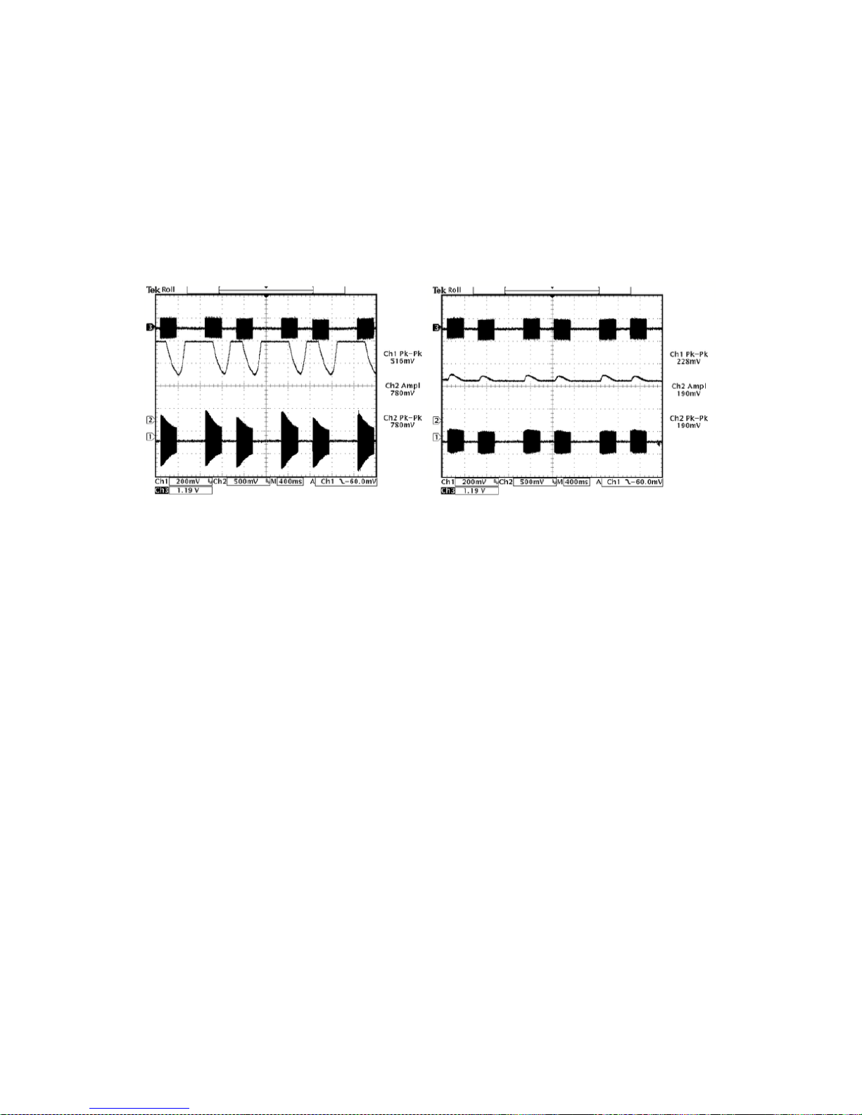
Over the course of the next few pages we have included several scope shots clearly
illustrating the input and output of the single band AGC together with the AGC control
signal. The effect of the control signal is clearly evident on the output audio waveform.
These scope shots help to visually illustrate the concepts under discussion. The multi-band
AGC stage is designed so that a 0VU input level to the processor will drive the multiband
AGC to the midway resting level of 0dB.
Individual drive controls are provided as a way of equalizing the audio before
processing. This can be used to add a touch of more presence or bass. Keep in mind
that the multiband AGC by its very nature will tend to compensate any cut or boost you
make here.
The attack and decay times of the AGC have a range of 1-10 and this corresponds to
time constants of 100mS to 30S. We suggest an attack somewhere in the region of 3-4
and a decay setting of 1 or 2 positions higher than that.
Effects of time constant speeds
The AGC stages in the DSPXtra-AM Encore are gated. This slows down the release time
of the multi-band AGC when the program material drops below a certain level, which
prevents noise suck up and gain hunting from occurring during quiet periods or lulls in
the audio.
AGC attacking and decaying with
faster time constants.
AGC attacking and decaying with
slower time constants.
9 - 15
The DSPX has three controls that affect gating. The first is the gate level and this can be
adjusted over a range of -20 dB to -40dB. This is the level at which the program material
must fall below for the gate to become active. The gate level control has two more
options, OFF and ON. OFF is self-explanatory and prevents the gate from having any
effect. ON is often referred to in this manual as 'forced gating' as it has the effect of
switching the gate on at all times with any level of program material. This option is used
to bypass the AGC and provide a fixed gain through it.
Effects of gating
Under gated conditions, the gain reduction will slowly move to the average gain the
AGC had in the recent past. This preserves the frequency balance of the program
material when the multiband AGC is gated.
9.5.4 MULTIBAND LIMITERS
The multi-band limiters drive can be adjusted over a +/- 12 dB range. Increasing the
drive will increase the level of limiting and with it on air loudness, above a certain level of
drive no more loudness will be obtained and all that will happen is you will generate
higher levels of IM distortion and the sound will take on a busy, packed texture. You may
also observe higher levels of high frequency noise when the band 3 and 4 drives are
increased. We don't usually find much use for drives above +6 dB but more may be
required if other settings are adjusted to compensate. In any case, observe the peak
limiter meters for a good indication of how much drive to use. We don't recommend
more than 12dB of gain reduction especially on bands 4, 5 and 6. Gain reductions of 4-8
dB are a good compromise between loudness and quality.
The multi-band limiters in the DSPXtra-AM Encore are of the dual time constant variety.
There is an attack and decay to handle the peaks and an attack and decay to handle
the average level of limiting. Understanding how the two time constants interact is
imperative if you want to make major changes to how each bands limiter reacts. We
have included some scope screen captures to illustrate things a little clearer. The peak
and average function can clearly be seen in the images.
AGC attacking and decaying with
gating disabled.
AGC attacking and decaying with
gating enabled.

9 - 16
Traditionally audio limiters have two time constants, an attack, the time is takes the
limiter to respond to a signal above the threshold and a decay or release which is the
time is takes to respond to a drop in level. In a traditional audio limiter the attack time is
usually set to somewhere in the region of a few milliseconds and the decay time
considerably longer at somewhere in the hundreds of milliseconds. This is not the most
optimum solution because transients that last only a few milliseconds will reduce the
level of the waveform for hundreds of milliseconds, reducing loudness and creating
audible pumping effects.
The solution is multiple time constants where one set of time constants can be set to
handle the fast peaks and another to handle the average level of limiting. Fast transients
will release in a faster less noticeable way and won't punch holes in the sound in a way
that single time constant limiters can. The secondary slower time constant circuit will not
have much effect on the audio waveform when hit with a transient because the higher
attack time, generally in the hundreds of milliseconds will not allow a build-up of energy.
In the case of a sustained envelope of audio above the threshold the multiple time
constant will attack as normal with the peak time constant but the sustained energy will
also charge the secondary slower circuit.
When the audio energy falls away and the circuit goes into release the peak decay will
dominate until it reaches a point where it hands over to the slower secondary time
constant for a slower rate of decay. The illustrations show this to good effect, where
transients have a fast release but multiple or sustained transients build up energy in the
secondary circuit which acts as a platform for the peak to release to. The secondary
circuit's platform can be thought of as the average level of limiting. Having this fast peak
responding circuit ride on top of the average circuit creates many advantages, limiter
transparency, less chance of pumping and greater loudness. By setting the time
constants appropriately we can have the multiple time constant based detectors work
as peak handling, average handling or the optimum setting of a balance of the two.
The peak attack time should be set to the desired attack time required from that limiter.
The range is 1-10 which corresponds to 1 to 00mS on an exponential scale. The peak
decay time should be set to the desired peak decay time required for transients. The
range is 1-10 which corresponds to a decay time of 10 to 1000mS.
The average attack time is perhaps the most important control in the dual time constant
detector as it sets the balance between peak and average energy in the detector. With
smaller numbers more energy is transferred into the average circuit and a higher
platform level is created so more time will be spent releasing at the slower average rate.
Higher numbers offer slower attack times for the averaging part of the detector and this

9 - 17
has the effect of lowering the average platform level and allowing the peak part of the
circuit to dominate with its faster release times.
The average decay time can usually be viewed as the nominal release time of the
detector, similar to a standard single time constant limiters release time.
To recap, the peak attack time and average decay time play the same sort of role as
that of a standard conventional single time constant based limiter.
The peak decay time sets the decay time for fast usually inaudible transients and the
average attack time sets the ratio of peak to average control and defines the position
of the platform that the peak circuit releases to.
9.5.5 MIXER
The post limiters mixer in the DSPXtra-AM Encore is not strictly a mixer but a band output
level control where small EQ changes can be made.
Be careful when making large EQ changes at this stage because there is no peak
control prior to the clipping system. It is easy to overload the clipping stages by setting
these controls all to large positive values.The control range for each band of +/- dB is
purposely restricted for these reasons.
!!

9 - 18
9.5.6 BASS CLIPPING
The DSPXtra-AM Encore, like most competent broadcast audio processors, has a bass
clipper prior to the final clipper.
The purpose of the bass clipper is to keep low frequency energy to a pre-determined
level to allow for the summation of the other bands. Without the bass clipper the bass
signal can push the mid and HF audio waveforms into the final clipper, creating audible
IMD, the worst type of distortion. By restricting the bass to a certain level the mid and HF
energy has its own reserved space in the summated waveform and we reduce the
likelihood of bass generated IMD.
The downside to bass clipping is you are restricting the bass to a lesser level than what it
would be without it. The upside is that moderate levels of bass clipping won't cause a
large loss of bass loudness and should have minimal audible artefacts.
When bass-clipper is being driven more aggressively you will start to notice generated
distortion. This distortion can be used to actually give the illusion of more bass, especially
on smaller radios that are incapable of producing the lower frequency fundamental
bass waveform.
This can be viewed as an upside of bass clipping. You need to decide what level of bass
clipping is acceptable to your format, both in creating room for summation from the
other bands and making the punch/distortion trade-off.
9.5.7 FINAL CLIPPER
The final clipper is a sophisticated highly over-sampled peak limiter that incorporates
distortion-controlling techniques, and has an embedded 1kHz low-pass filter.
This section of processing is the last line of defence in the processing and is also the most
critical part in the loudness/quality trade-off. While each of the preceding processing
stages play a part in reducing the peak to average ratio of the audio waveform none
has the same effect on the peak to average ratio as the final clipper.
Great care is needed in setting the final clipper drive control. This control needs to be
adjusted carefully and only you can make the decision on the balance between
loudness and quality.
As you increase the drive you will obviously obtain more loudness but at the expense of
distortion. There is a fine line between artistic distortion and distortion that your listeners
will find uncomfortable to listen to, especially for extended periods of time.
The final clipper has an additional control to help reduce IMD distortion. The ‘clipper
hardness’ control is an additional program dependent mechanism that helps to reduce
distortion by analysing the level of IMD, and dynamically adjusting time constants.
The control is subtle and its range has been limited to restrict the amount of control,
preventing pumping and a loss of loudness which would undo what we want to use the
clipper for - which is gaining loudness.
9 - 19
9.5.7 LOW PASS FILTER
To comply with the bandwidth requirements of the AM transmission, the DSPXtra-AM
Encore has an adjustable low- pass filter. This low pass filter is tightly integrated in the
processing stages and provides full protection with all international standards (masks).
The frequency of the filter is user adjustable over a wide range - from 4kHz to 10 kHz in 0.5
kHz steps. If you need to comply with the NRSC 10 kHz bandwidth for analog AM
transmission mask, set the filter to 10 kHz. To comply with the NRSC 8 kHz bandwidth for
analog portion of Hybrid AM IBOC transmission, you need to set the filter to 7.5kHz.
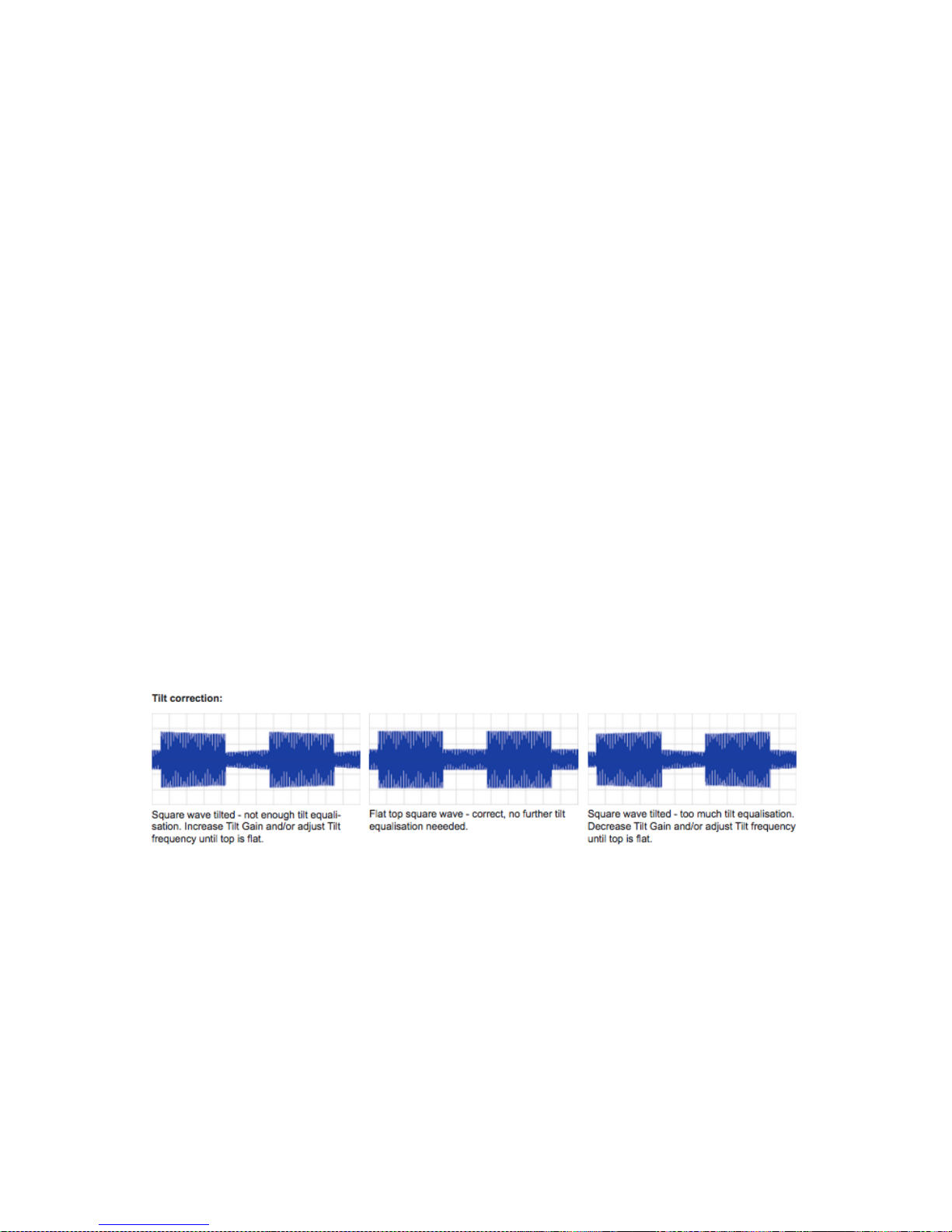
9.5.8 TILT EQUALISATION
AM transmitters (especially older ones) might have DC blocking capacitors in the input
circuits to remove DC offset. However, when presented with the processed signal
resembling square wave, this high-pass filters causes the signal to tilt, producing
overshoots and robbing you of modulation.
There are two things you can do to prevent this and optimise your modulation usage.
The best solution is to remove (or at least increase) the capacitors in the input circuits in
your transmitter. The DSPXtra-AM Encore has no DC offset and therefore these
capacitors are not necessary when the unit is connected directly to the transmitter.
If you for some reason, can't remove these capacitors then you can try to compensate
for the tilt by using the DSPXtra-AM Encore's built-in tilt equaliser. To do this, you need to
connect the DSPXtra-AM Encore to the transmitter, navigate to the Oscillator menu and
turn the oscillator on. Set the type to square, frequency to 0 or 100 Hz and amplitude to
no more than 0%. Connect the DC-coupled oscilloscope to the transmitter's RF envelope
monitoring output and while observing the waveform on the scope, adjust the Tilt EQ
and Tilt Gain controls to obtain a flat top waveform.
9.5.9 ASYMMETRY
In some countries (USA, for example) stations are allowed to modulate asymmetrically
(modulate positive peaks higher than negative peaks) to increase loudness. The
DSPXtra-AM Encore has the ability to change the symmetryof its clippers and clip
positive peaks up to 150% while keeping the negative peaks at 100%. In order to keep
the negative peaks at 100% when changing the asymmetry, a DC path in the input
circuit of the transmitter is required. Otherwise the DC coupling will re-symmetrise (offset)
the asymmetrically clipped signal.
If the balanced connection to the transmitter is not wired correctly or for some other
reason is inverted, instead of increasing the positive peaks, negative peaks in the

9 - 20
transmitter will be increased. To correct this you can use the polarity switch in the Output
menu.
Keep in mind that while operating the clippers asymmetrically might increase the
loudness, it will also increase odd harmonics (and therefore overall distortion) as well as
the inter-modulation distortion. Operating clippers symmetrically will always produce
cleaner and less fatiguing sound.
!

9 - 21
9.6 GETTING THE SOUND YOU WANT
While the DSPXtra-AM Encore can help you obtain the sound that you want we must
always take into account the limitations presented to us by the transmission channel.
The trade off in any audio processor is loudness vs. quality. The mark of how good a
processor is, is how loud the processor can be whilst maintaining sufficient quality. It is up
to you where this loudness / quality trade off point is set. This point is also usually market
and format dependent.
In the effort to squeeze as much bass and high frequency energy into the peak limited
channel we must make compromises. Bass takes up a lot of room in the waveform and
pursuit of a 'mega bass' type sound will leave you less room for high frequencies. When
processing aggressively we usually will have to accept a certain level of bass distortion in
making room for high frequencies or we will have to accept a certain level of high
frequency distortion if our desire is lots of clean loud bass.
If your aim is a cleaner sound and a slight loss of loudness is not important then it is easier
to get the tonal characteristic you're after without distortion. Lower clipper drives will
provide you with clean bass and crystal clear razor sharp high frequencies. The choice is
yours.
9.6.1 MORE LOUDNESS
Loudness can be increased in several ways:
Multiband AGC: Increase the drives to the bands;
Speed up the release times;
While it is possible to create a strange response in the multi band AGC, it is hard to produce distortion because
whatever gets through the AGC is dealt with by the
following peak limiters.
Multiband limiters: Slow down the peak attack times, letting more through to
the clippers;
Speed up the release times of the average release time
constants;
Slow down the average attack time so that the peak time
constants dominate the control signal providing faster
control;
Increase the master limiter drive;
Increase the individual limiter drives.
Final clippers: Increase the final clipper drive and increase its hardness
control to a higher number. Increase composite clipper
drive.
Extra loudness can be obtained by working on only a single or a couple of the above
suggestions. You are likely to run into trouble if you ‘crank up’ all of the above settings.
You are likely to generate excessive distortion in the final clippers and cause a fatiguing
sound if you're not careful. Less can be more. Make small changes and compare
against the settings of the factory presets if you find you have lost your way somewhere.

9 - 22
9.6.2 MORE CLARITY
We can obtain extra clarity and ‘quality’ in several ways:
Multiband AGC: Slow down the release times;
Multiband limiters: Speed up the peak attack times, letting less through to the
clippers;
Slow down the release times of the average release time
constants;
Speed up the average attack time so that the average
time constants dominate the control signal - providing
slower control;
Decrease the master limiter drive;
Decrease the individual limiter drives.
Final clippers: Decrease the final clipper drive;
Decrease the clipper hardness control;
Decrease the composite clipper drive.
9.6.3 MORE BASS (LF)
We can obtain more bass in several ways:
Bass Enhancement: Increase the peaking filter gain. Increase the peaking filter
Q factor.
Multi-band AGC: Increase the drive to the AGC band 1;
Speed up the AGC band 1 release;
Lower the AGC band 1 gate threshold, allowing more gain
to be applied to low level bass waveforms. Consider 'force
gating' the AGC band 1 so the multi-band AGC for band 1
is bypassed.
Multiband limiters: Increase the band 1 and band 2 limiter drive;
Slow down the peak attack time for band 1, letting more
through to the clippers;
Speed up the release time of the average release time
constant of those bands;
Slow down the band 1 and band 2 average attack time so
that the peak time constant dominates the control signal
providing faster control.
Bass clipper: Increase the bass clip level.
!

9 - 23
9.6.4 MORE TREBLE (HF)
There are several ways of increasing the HF content of the audio. When processing for
AM we need to use distortion controlled clipping to preserve as much of the high
frequency content as possible, which will be removed by the de-emphasis curve in the
listeners’ radios. The ‘HF clipping’, band 'drive' and ‘peak attack’ controls govern the
amount of high frequency distortion-controlled clipping that is performed.
Multiband AGC: Increase the drive to the AGC band 4;
Speed up the AGC band 4 release time;
Lower the band 4 gate threshold, allowing more gain to be
applied to low level HF waveforms;
Consider 'force gating' the AGC band 4 so the multi-band
AGC for band 4 is bypassed.
Multiband Limiters: Increase the bands 5 and 6 limiter drive;
Slow down the peak attack time for bands 5 and 6 and
speed up the peak release time;
Reduce band 5 to band 6 coupling;
Set the HF clipping control to higher numbers - which shifts
control from the limiters to the distortion-controlled HF
clipper.
In all processor adjusting, we suggest only small modifications from factory preset
settings if you are modifying lots of the parameters. If you are adjusting only a couple
from the above suggestions then you probably have a bit more leeway.
It is very easy to lose your way once you start 'tweaking' lots of different settings!

10 - 1
Menu Structure 10
DSPXtra-AM Encore menu structure
PRESETS >
F1 Bypass
F2 General
F3 General bright
F4 General heavy
F5 General Heavy Bright
F6 Talk
F7 Talk bright
F8 Talk heavy
F9 Talk heavy bright
F10 News
F11 News bright
F12 Sports
F13 Sports bright
F14 Music
F15 Music bright
F16 Music open
F17 Music open bright
F18 Loud
F19 Loud bright
F20 Classical-jazz
F21 Classical-jazz bright
U1 to U10 user presets.
[each preset contents identical]
Name [qwerty]
EQ
bass peak freq (60Hz - 120Hz)
bass peak q (-0.4 – 4dB)
bass peak gain (0 - 6dB)
hf shape (0 – 10)
hf gain (0 – 20dB)
hf emphasis shape(1-10)
hf emphasis gain (0-20dB)
AGC
BAND 1
drive (-6 – 6)
attack (1-10)
release (1-10)
gate enable (off/on)
BAND 2
drive (-6 – 6)
attack (1-10)
release (1-10)
gate enable (off/on)
BAND 3
drive (-6 – 6)
attack (1-10)
release (1-10)
gate enable (off/on)
BAND 4
drive (-6 – 6)
attack (1-10)
release (1-10)
gate enable (off/on)
MB LIMITER
master drive (-12dB - +6dB)
BAND 1
drive (6dB – 12dB)

10 - 2
peak attack (1-10)
peak release (1-10)
compr attack (1-10)
compr release (0-10)
BAND 2
drive (6dB – 12dB)
peak attack (1-10)
peak release (1-10)
compr attack (1-10)
compr release (0-10)
BAND 3
drive (6dB – 12dB)
peak attack (1-10)
peak release (1-10)
compr attack (1-10)
compr release (0-10)
BAND 4
drive (6dB – 12dB)
peak attack (1-10)
peak release (1-10)
compr attack (1-10)
compr release (0-10)
BAND 5
drive (6dB – 12dB)
peak attack (1-10)
peak release (1-10)
compr attack (1-10)
compr release (0-10)
BAND 6
drive (6dB – 12dB)
peak attack (1-10)
peak release (1-10)
compr attack (1-10)
compr release (0-10
MIXER
band 1 level (-3 – 3dB)
band 2 level (-3 – 3dB)
band 3 level (-3 – 3dB)
band 4 level (-3 – 3dB)
band 5 level (-3 – 3dB)
band 6 level (-3 – 3dB)
CLIPPER
bass clip level (-10 – 0)
main clip dist ctrl (1-10)
finesse (1-10)
hardness (1-10)
main clip drv (-6 – 6dB)
SLEEP [Causes immediate OLED blank and LED ring ‘breathe’.]
SYSTEM!
AUDIO I/O
INPUTS
source (analog/digital)
max peak analog level (0 – 24dBU)
max peak digital level (-30 – 0 dBFS)
right trim (-3 - +3dB)
mode (stereo, mono l+r, mono from l, mono from r, swap l/r)
hp filter (off, 20, 30, 40, 50, 60Hz)
OUTPUTS
low-pass filter (7, 7.5, 8, 8.5, 9, 9.5, 10kHz)
tilt freq (5, 10, 15, 20, 25, 30, 35, 40, 45, 50Hz)
tilt eq (0-10dB)

10 - 3
asymmetry (100-150%)
polarity (normal/inverse)
TONE GENERATOR
oscillator (off, sine, square)
frequency (50, 100, 200, 400Hz, 1, 2, 4, 10kHz)
amplitude (10 – 120%)
analog output level (-18 – 24dBu)
analog output level (-18 – 24dBu)
digital sample rate (48, 96, 192kHz)
digital output level (-26 – 0dBFS)
headphone level (0-100%)
headphone source (none/analog input/digital input/test
tone/processed)
SCHEDULER
SCHEDULE (1…8)
run (never/once/repeat)
days (su/mo/tu/we/th/fr/sa/smtwtfs/mtwtf/ss)
start time (hh:mm:ss)
load preset (F1-F12, U1-U8)
EVENTS
GPO PIN CONFIG
PIN 1…4
mode (event action/an input/dig input/an output/dig output/mpx gen
output/unit temp)
polarity (HiZ/low)
EVENT 1…8
active (off/on)
trigger (analog input/analog output/digital input/digital output/
temperature/gpi1/gpi2/gpi3/gpi4)
condition (equal to/not equal to) or (more than/less than)
value (on/off) or (value appropriate to trigger)
for this time (0 to 60s)
revert (yes/no/delay)
delay time (0 to 12s)
set/change (none/input source)
to (dependent on choice above)
load preset (F1-F10, U1-U8)
set GPO pin (none/pin1/pin2/pin3/pin4)
email (none/admin/user1/user2/user3)
send snmp (yes/no)
TIME
uptime (display of dd:hh:mm:ss)
time set (hh: mm: ss: mm/dd/yyyy)
ntp (off/on)
update now run (command)
host (name or IP number)
period (1hr/12hr/24hr)
USERS
ADMIN
password pass (default)
email (email address)
USER 1…3
password pass (default)
email (email address)
privilege (view/control)
COMMUNICATIONS
IDENTITY
system name

10 - 4
site number
lat/long (xxx.xxx yyy.yyy)
ETHERNET
dchp (off/on)
dns (off/on)
ip
subnet mask
gateway
dns 1
dns 2
mac
link (down/up)
EMAIL
sender
mail method (bw/smtp)
smtp server
authenticated (yes/no)
smtp password
TEST
recipient (admin/user1/user2/user3)
send test test
WEB REMOTE
active (off/on)
port 80
SNMP
enable (off/on)
port 161
community
read only (off/on)
name
description
TELNET
active (off/on)
port 23
logging
serial (on/off)
file (on/off)
filename/location
udp (off/on)
udpip
udpport
test logging run (command)
RS232
active (yes/no)
baudrate (9600/19200/57600/38400/115200)
about
product
serial#
bootloader
hardware
os ver
media engine ver
front panel ver
power supply ver

11 - 1
!
Routing & Block Diagram 11
Please see below for an audio, RF and RDS data routing diagram.
This can help you understand the enormous capabilities of the Encore family of
products!
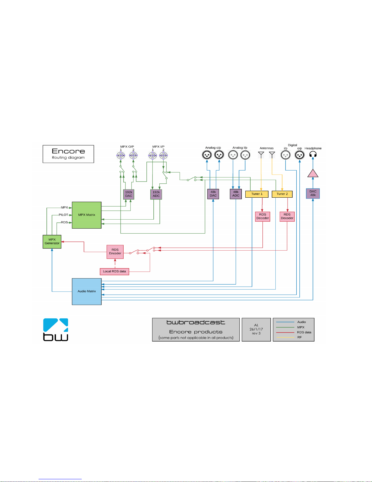
11 - 2
!
!

12 - 1
Technical Specification 12
Encore family specifications. Certain parameters are irrelevant in some products.
TUNER (Dual)
Inputs 2 x 50 ohm, BNC female
Tuning range 65-108MHz in 50kHz or 100kHz steps
IF bandwidth 56kHz - 311kHz dynamic or fixed
De-emphasis 75µs, 50µs or Off
SNR (Mono/Stereo) -79dB / -60dB
THD (Mono/ Stereo) 0.011% / 0.16%
Stereo Separation >50dB
Adjacent / alternate channel rejection 70dB / 74dB
RF input level RF 0.5V to 2V
ANALOG INPUT
Nom. input level +4 dBµ
Max input level +24 dBµ
Connectors XLR balanced EMI suppressed
A/D conversion 24 bit
Distortion <0.01%
ANALOG OUTPUT
Analog output 0-24 dBµ adjustable
Connectors XLR balanced EMI suppressed
D/A conversion 24 bit
Audio monitoring output on jack +12dB maximum
DIGITAL INPUT (AES/EBU)
Sampling rate 32-192 kHz (MPX over AES ready)
Connector XLR balanced EMI suppressed
Nominal input level -20 dBFS
DIGITAL OUTPUT (AES/EBU)
Sampling rate 32-192 kHz (MPX over AES ready)
Connector XLR balanced EMI suppressed
Level -32 - 0 dBFS adjustable
MPX / RDS
Output level 0 - 12 dBµ adjustable
MPX outputs 2 x BNC EMI suppressed
D/A conversion 192KHz, internally oversampled
Stereo separation >60 dB 20Hz - 15 kHz
MPX inputs 2 x BNC EMI suppressed
A/D conversion 192KHz, internally oversampled
Pilot output BNC software switched with MPX2 output
REMOTE CONTROL
Connectors Serial, USB A, USB B, RJ45
Protocols HTTP (browser, mobile, API), SNMP, TELNET, FTP, SMTP,
RS232
PHYSICAL
Power 90-260vAC, 50/60Hz, 25w IEC connector.
Size (inch) 19W x 1.73H x 9.84D
Size (mm) 482W x 44H x 200D
Weight 1.6kg

12 - 2
This manual was written by Andy Linton. © BW Broadcast Ltd. 2017. E&OE.
Encore products are manufactured in the UK by BW Broadcast Ltd. IO Centre, Croydon Road,
Croydon, CR0 4WQ, UK. Tel: +44 208 253 0290. US toll-free: 1-866 376 1612.
Email: support@bwbroadcast.com
‘Encore’ is a trademark of BW Broadcast Ltd.
 Loading...