

Page 1

Digital Video Surveillance
Network System
SCode
(V3.3)
User’s
Manual
1 / 143
Page 2

Notes
1. Please read this manual carefully, before installing or operating this product.
2. Before using the step-by-step user’s manual, please read the system
introduction.
3. Windows NT, Windows 2000, Windows XP and Words are registered trade
marks of Microsoft Corporation.
4. This product pass CE and FCC test.
CE number : W6M20504-5792-E-11
FCC number : W6M20504-5792-P-15B
Remark: The word Windows, mentioned in this user’s manual refers to
Windows NT, Windows 2000, or Windows XP
2 / 143
Page 3

Chapter 1 System Introduction...............................................5
1.1 System Components .........................................................5
1.2 User Interface: Operation and Display............................... 7
Chapter 2 Installation ..............................................................12
2.1 Hardware Installation....................................................... 12
2.2 SCode DVR Software Installation....................................13
2.3 SCode RMS Software Installation ...................................13
Chapter 3 System Operation.................................................14
3.1 General Display...............................................................15
3.2 Operation Functions ........................................................16
3.3 PTZ Panel........................................................................24
3.4 Control Panel................................................................... 25
3.5 On-Screen command....................................................... 27
Chapter 4 System Setup.........................................................29
4.1 Camera Setup.................................................................. 30
4.2 File Setup......................................................................... 35
4.3 Auto Setup.......................................................................37
4.4 Communication Setup .....................................................39
4.5 User Setup.......................................................................40
4.6 Schedule Setup ...............................................................42
4.7 I/O Device Setup.............................................................. 45
4.8 Alarm Setup..................................................................... 49
Chapter 5 Monitor and Record..............................................55
5.1 Manual Recording............................................................ 55
5.2 Schedule Recording ........................................................56
5.3 Video Monitoring..............................................................57
5.4 Window Edit.....................................................................58
5.5 Motion Image Detection...................................................59
5.6 Camera Alarm.................................................................. 59
5.7 Instant Playback ..............................................................60
Chapter 6 Playback..................................................................62
6.1 File Search.......................................................................63
6.2 Playback Operation .........................................................72
6.3 Import Files...................................................................... 75
6.4 Export Files......................................................................76
6.5 System Setup ..................................................................77
6.6 Format of File Name........................................................ 80
3 / 143
Page 4

Chapter 7 Snapshot.................................................................81
7.1 Snapshot.......................................................................... 81
7.2 View Pictures................................................................... 81
7.3 Viewer Program............................................................... 82
Chapter 8 PTZ Control.............................................................84
8.1 PTZ Panel........................................................................84
8.2 Control Panel................................................................... 85
Chapter 9 eMAP........................................................................87
9.1 Setup eMAP..................................................................... 87
9.2 Open eMAP..................................................................... 93
Chapter 10 Remote Access....................................................97
10.1 System Introduce...........................................................97
10.2 SCode RMS Installation................................................. 97
10.3 SCode Network Structure.............................................. 98
10.4 SCode Server................................................................ 99
10.5 SCode Client................................................................ 107
10.6 Link SCode DVR to SCode Server.............................. 142
4 / 143
Page 5

Chapter 1 System Introduction
Before using the step-by-step user’s manual, it might be a good idea to familiarize with the
system as a whole and the user interface to prepare yourself what to expect and to be able to
place it in its context.
1.1 System Components
1.1.1 Hardware
Camera SP-5200 card SCode DVR Speakers
Your system’s hardware consists of the cameras connected to SCode SP-5200 capture cards
in your computer that enable the capturing and compressed storage of the video signals,
which can also be activated by a time schedule and/or motion detection by the cameras or
possibly additional attached external devices.
1.1.2 Software
The SCode DVR software provides professional video surveillance tools.
The additional SCode Client and SCode Server programs provide IP secure remote access
and control of any SCode DVR and cameras, anywhere in the world, through the data
network.
5 / 143
Page 6

1.1.3 Remote access
Here below is an example of SCode RMS (Remote Monitoring System) network structure:
SCode RMS has 4 unites :
■ SCode DVR
■ SCode Client
It is a computer where the SCode Client program is installed. To observe from a remote
site, you just install the Client program on a suitable computer or a portable device.
■ SCode Server
It is a computer where the SCode Server Program is installed. SCode Server program is
usually run on a dedicated server embedded in a LAN or WAN of SCode DVRs, to
facilitate the communication and data traffic with the client SCode DVRs, however the
SCode Server program and SCode Client program can be installed together on a single
SCode DVR when standing alone.
■ SCode Center Server
It is a computer where the SCode Server Program is installed. And this SCode Server is
appointed as a center server.
The communication is controlled by the SCode Server. SCode Client software provides the
tools for the remote access. SCode DVRs can be accessed by one, or more SCode Clients,
simultaneously. With SCode Client, you can access the remote SCode DVRs in your local
network by through SCode Server; or you can link direct to other remote SCode Servers and
go into their network to access SCode DVRs, or you can link to SCode Center Server and go
into its sub-server to access SCode DVRs, giving you the capability to monitor and operate
thousands of cameras, and manage their systems from one centre.
1.1.4 Installation steps
Put the SCode SP-5200 capture card into a PCI slot and Window’s Add New Hardware
Wizard will help you to copy the provided system-ware from the installation CD. Then run
the installation program to install the SCode drivers.
6 / 143
Page 7

1.2 User Interface: Operation and Display
1.2.1 Operation usage
You can follow standard M.S. Windows practice, to operate the SCode software.
1.2.2 SCode DVR : where to find what
SCode DVR has 2 kinds of main displays: Normal Mode and PTZ Mode.
(1) GUI in Normal Mode
Active image window
Image window
Information window
The operation panel is hidden. <
(2) GUI in PTZ Mode
The PTZ panel is hidden. < > to open it.
Operation panel
Control panel
PTZ panel
> to open the operation panel.
7 / 143
Page 8

(3) Normal mode and PTZ mode
If you want to access the PTZ Mode, < >. The display will switch from the Normal
Mode to PTZ Mode. The button,
, is located in the right-up corner.
Normal mode PTZ mode
(4) Image window
The Image windows show the incoming video signals from the cameras (Video
channels). Before any operation, always select and activate the window. A white
borderline around the camera window indicates which window is active.
By clicking on
to show the spilt mode selection.
You can select one of the splits modes for display on the screen. If the display is in 1channel mode or in 4-channel mode, you can activate the Auto page switch function
(
) to display 1 channel, or the set with 4 channels, appearing one after the other,
super imposed on the display.
(5) Information window
The Information window shows the current system date and clock and the information
of the active window. These information is included : the channel number, camera name,
the starting recording time and evolved recording time, the remaining space available on
the current working HDD, the recording speed, and the monitoring speed.
8 / 143
Page 9

(6) Control panel
PTZ control Setup control Host
In this Control panel, you can view the system information and or activate functions and
settings for video, alarm features. You all also can control the camera platform, the
speed dome, and I/O device.
(7) PTZ panel (P = Pan, T = Tilt, Z =Zoom)
On PTZ panel are the setup controls for the activated camera plate or the speed dome.
You can click
to open or close PTZ panel.
9 / 143
Page 10

1.2.3 Operation Panel
The some function of Operation panel is hidden by this cover. < > for access.
There are 12 function keys in the hidden area.
Schedule : Eanable the preset recording schedule.
Snapshot : Take a picture from the active image window.
View picture : View a stored picture.
Split mode : Click this button. The Split control panel will be opened.
Alarm mask setup : Change the operation of the mouse to be SET MASK mode.
Open speaker : Not provide in SCode V3.3
Video signal adjustment
Adjust the camera’s Brightness, Contrast, Saturation, and Hue
HDD information : View the HDD status.
Show camera information : Show/Hide/Set OSD of camera information.
Communication link : Link or Unlink with SCode Server.
eMAP : Open or Setup eMAP.
System setup: Set up the system
10 / 143
Page 11

There are 5 often used functions which are not hidden into the operation panel.
System information : View the record of the alarm log, the login/logout, the operation.
Lock : Lock or Unlock Program.
Start all cameras to record
Stop all cameras recording
Play : Call Player program
1.2.4 Other Functions
Power off : Turn off this porgam
There are 3 buttons located in the up-right coner.
Switch mode : Swap the Simple Mode and Control Mode of the GUI.
Minimum : Minimize the SCode program.
Close : Close SCode program.
11 / 143
Page 12

Chapter 2 Installation
2.1 Hardware Installation
1. Plug the SCode SP-5200 capture card(s) in a PCI slots. The card closest to the VGA
card will be automatically defined as card number 1, with camera number 1-4. (Channel)
2. Turn on your computer. Windows will detect the SCode SP-5200 card and will start the
Add New Hardware Wizard. The new hardware will be detected as Multimedia
Video Controller and Windows will ask to install its driver.
Follow the installation instructions of the wizard again to load its hardware driver from
the folder, \ SCode_Driver. For each SP-5200 card, Windows will ask you to install
this driver 1 time.
3. After the above drivers are installed, the system will return to Windows.
NB : SCode V3.3 does not support Intel’s Intel HT (Hyper Threading ) technology.
If your mother board does support Intel HT, make sure that before you install your
system’s O.S. Windows, to go first in the BIOS setup and disable the HT function.
If the HT function is not disabled in the BIOS before, but after installation of O.S.
Windows, Windows will still force the mother board to work in HT.
12 / 143
Page 13

2.2 SCode DVR Software Installation
1. Insert the SCode installation disc into the CD drive.
2. Execute \SCode_DVR\SCodeV33_DVR_EN_PAL.exe (in PAL areas)
Or \SCode_DVR\SCodeV33_DVR_EN_NTSC.exe (In NTSC areas)
Or \SCode_DVR\SCodeV33_DVR_DE_PAL.exe (In German)
3. Then, follow the instructions of the setup program to finish the SCode installation.
4. Reboot your computer. The SCode software installation is completed.
2.3 SCode RMS Software Installation
1. Install SCode Server Program
(1) Insert the SCode installation disc into the CD drive.
(2) Execute \SCode_RMS\SCodeV33_Server_EN.exe
Or \SCode_RMS\SCodeV33_Server_DE.exe (In German)
(3) Then, follow the instructions of the setup program to finish the SCode_Server
program installation.
2. Install SCode Client Program
(1) Insert the SCode installation disc into the CD drive.
(2) Execute \SCode_RMS\SCodeV33_Client_EN.exe
Or \SCode_RMS\SCodeV33_Client_DE.exe (In German)
(3) Then, follow the instructions of the setup program to finish the SCode_Client
program installation.
13 / 143
Page 14

Chapter 3 System Operation
Run the SCode DVR software
Execute SCode DVR program and the login dialog will appear :
(The default user name = admin, Default password = admin)
After select one user and input its password, this general display will appear:
Simple Mode (GUI)
14 / 143
Page 15

3.1 General Display
SCode DVR program has 2 GUIs: Normal Mode and PTZ Mode.
The following figure describes the name of each unit of the general display:
Active image window
Image window
Information window
Operation panel
Control panel
PTZ panel
Normal Mode
PTZ Mode
15 / 143
Page 16

3.2 Operation Functions
3.2.1 Window control functions
1. Close : Turn off this porgam. A confirmation dialog will appear.
2. There are 3 buttons located in the up-right coner.
(1) Close : Close the SCode program
Minimum : Minimize the SCode program.
(2)
Switch mode : Swap the Normal Mode and PTZl Mode of the GUI.
(3)
3.2.2 Often used functions
1.
Playback
Open the playback functions. Please refer to Chapter 6 for the details.
2. Start all cameras to record
Click the button to execute the recording function of all cameras.
Stop all cameras recording
3.
Click the button to stop the recording function of all cameras.
4.
Lock
(1) Enable Password Protect Mode
< > to enable Password Protect mode.
16 / 143
Page 17

After confirmation, the system is locked and its icon will become
(2) Disable Password Protect Mode
<
> to unlock the system.
Select one user name and Input the password to release the protect mode.
If you want to change the password, go to the system setup to modify.
(Please refer to Section 45, User setup, for the details.)
.
17 / 143
Page 18

System information
5.
View the system records. The below dialog will appear:
(1) Click to find the system records after input the Begin date and End date.
The left table will show as below :
(2) Select one day listed in the left table. The table will show as below:
The user can check Alarm log, Login/Logout, and opeartion log by click their icon.
(3) The user can control the keeping date of the system record.
: The max. stored days is 90 days.
If a new alarm event occurs, will become . This key will remain red, till you
have clicked it to view the alarm log. After viewing, it will go back to
.
18 / 143
Page 19

3.2.3 Operation functions
1. Schedule
If the schedule recording is stoped by the manual, you can click this button to execute the
schedule recording function again. (Please refer to Section 4.6, Schedule Setup, for the
detials of the recording schedule setup).
2.
Snapshot
Activate the image window of which you want to take a snapshot
< > and a snapshot is automatically taken and the picture is saved as bitmap file into
a pre-appointed folder. (Please refer to Section 4.1, Camera Setup, for the details. And
please refer to Chapter 7 for the details)
3.
View pictures
A file dialog will enable you to select a folder and open the stored picture:
Select on picture’s file and the picture will appear in the Viewer program. (Please refer
to Chapter 7 for the details.)
19 / 143
Page 20

4. Split mode
Click this button. The Split control panel will be opened.
(1-split) : The activated window will be shown in 1-channel display.
If the Auto page switch is enabled, the images of the other channels will be
displayed one after the other.
(4-split) : It will show the 4 channel’s image of the active row to 4-split display.
If the Auto page switch is enabled, the sets of 4 channel display will swap to the
next set of 4 channels, alternatively
(9-split) : 1st ~ 9th channel will be shown in 9-channel display.
(16-split) : 1st ~ 16th channel will be shown in 16-channel display.
Auto page switch
The auto scan function can only be executed, if the system is either in 1-channel or
4-channel mode. Click this button to execute the auto scan function: the key will
become:
. Set the time-interval between the scans in the system setup dialog.
Full screen : Only show the image windows to the full screen.
5.
Alarm mask setup
Note : If you want to set up the alarm mask in one image window, you shall enable its
motion detection first
Please adhere to the following steps to set an alarm mask.
(1) Go into Camera setup of the system setup to enable the parameter, MD (Motion
Detection), which you want to put the alarm masks.
(2) Activate the window of the camera where you want to set an alarm mask.
(3) <
>. The mouse will go into Mask Setup Mode. becomes .
(4) Move the mouse on the active window. Click once with the left button of the mouse
at the top-left corner of the rectangular mask area that you want to draw. And then,
move the mouse to the bottom-right corner of the mask area that you want to draw.
Click once again and the mask area is set.
Sample of an alarm
mask area that is to
be drawn.
Move t h e mouse to
here. Click with left
button once.
Move the mouse to here.
Click with left button once
again.
The alarm mask
area i s drawn
.
(5) To set other alarm mask areas in this active window, repeat step 4.
NB : In each image window, up to 8 alarm masks can be set.
20 / 143
Page 21

1 ~ 8 masks can be drawn
in the image
No image change in the mask.
The mask is blue
.
The image is changing in the mask.
The mask is red
.
(6) If you want to clear or re-draw the alarm masks, move the mouse on this window
and click with right button: all masks will be cleared.
(7) < > The mouse will go back to Normal Mode. becomes .
(8). To set alarm mask areas to other cameras, please repeat steps 1 to 7.
6. Open speaker : Not provided in SCode V3.3
7. Video signal adjustment
Adjust the video signal’s parameters : brightness, contrast, saturation, and hue.
<
> to go back to the system default values.
<
<
> to save changes.
> Apply the new settings to all cameras to save changes.
21 / 143
Page 22
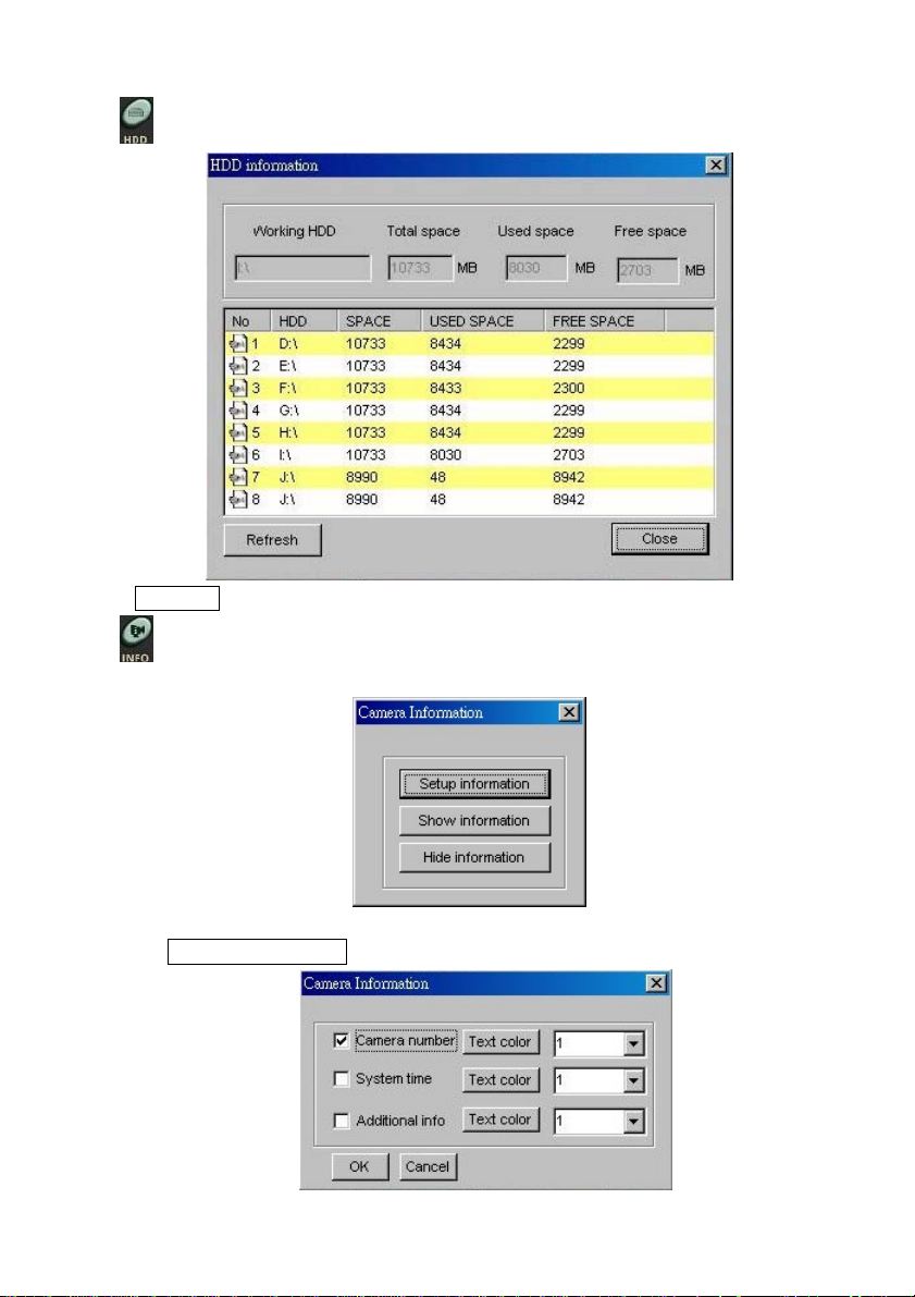
HDD information
8.
< Refresh > to update the status of the hard disks.
9. Show camera information
Click the button to open the setup window of the camera information, shown below:
(1) Set camera information
< Setup information >. It will open the following window,
22 / 143
Page 23

1) To enable the type of information in the image window, click: V or .
2) The enabled type information can be positioned in the window corners which is
followed the below setting.
< > and the following block will drop down. Select one position.
(1 = top-left, 2 = bottom-left, 3 = top-right, 4 = bottom-right)
3) < Text color > to change the text’s color from the below menu.
(2) Show the camera information on the screen
< Show information > to show the text on the image window.
(3) Hide the camera information
< Hide information > to hide the text from the image window.
10. Communication (Link to the SCode Server)
Click this button and the below window will appear.
(1) Mobile Phone (SMS) : Not provide in SCode V3.3
(2) UDP/IP : Please refer to Section 4.4, Communication Setup, and Chapter 10.
11.
12. System setup : Please refer to Chapter 4.
eMAP : Please refer to Chapter 9.
23 / 143
Page 24

3.2.4 Information window
The information window shows the below information :
1. Camera number : Cam =1
2. Camera name : cam1
3. Image motion detection status : in motion detection or blank
4. The starting recording time : rec=23:4:7
5. The current recording length : length = 0:0:50
6. The available space of the working HDD : F:\3969 M
7. The monitoring speed : M=21 fps
8. The recording speed : R=21 fps
9. The current system time : 23:04:57 2005/04/16
3.3 PTZ Panel
On the PTZ control panel, you can control P, T, and Auto function of a PTZ scanner or a
speed dome. You can click
(Please refer to Chapter 8 for the details.)
to open or close PTZ panel.
24 / 143
Page 25
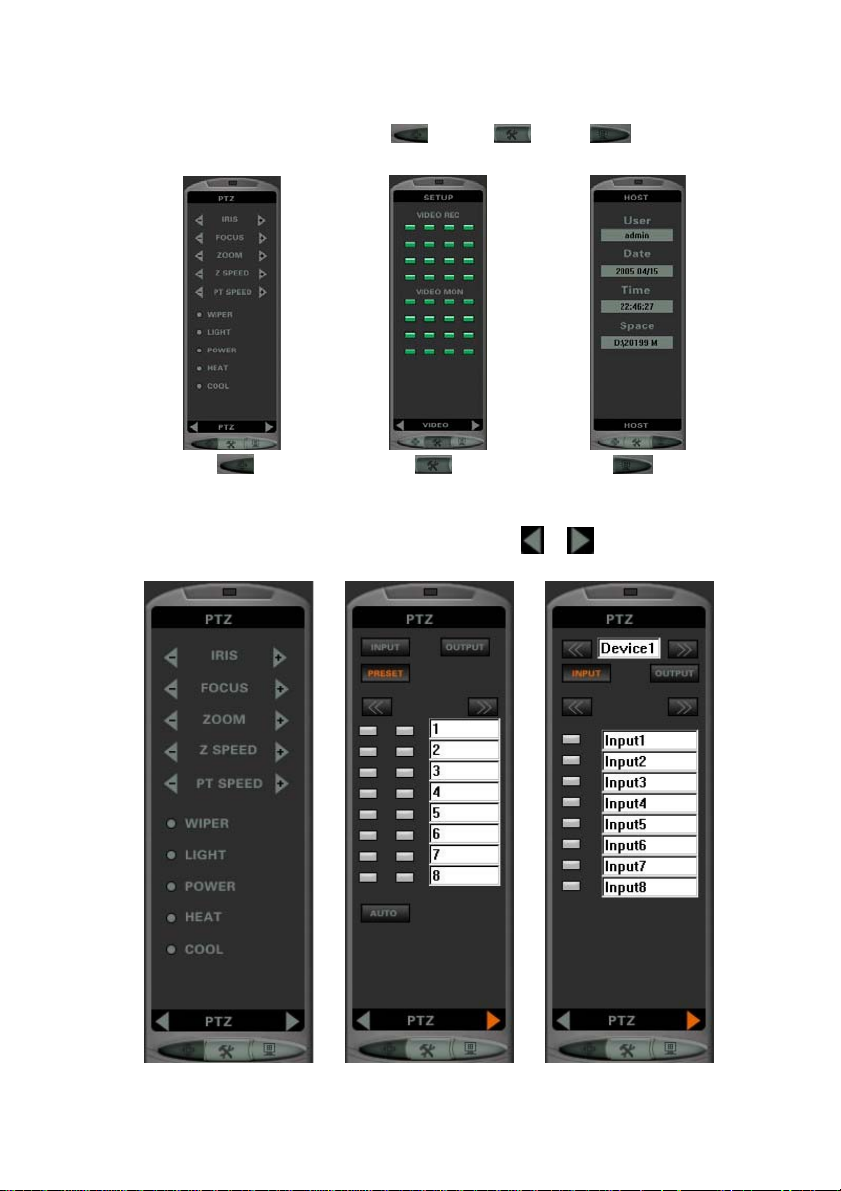
3.4 Control Panel
The panel has 3 sub control panels : PTZ ( ), Setup ( ), Host ( ). You can
change these modes by clicking their function key.
PTZ panel Setup panel Host panel
1. PTZ control
There are 3 sub control pages in PTZ panel. You can use
(Please refer to Chapter 8 for the details)
or to change these pages.
PTZ control (1) PTZ control (2) I/O device control
25 / 143
Page 26

2. Setup control
There are 2 pages in this Setup panel. You can use
These control panels allow you control each camera one by one.
or to change these modes.
Video Alarm
(1) Video control
Enable/Disable each camera’s Video Recording or Video Monitoring function.
(2) Alarm control
Enable/Disable each camera’s Motion-Detection or Camera-Alarm function.
Enabled : Disabled :
26 / 143
Page 27

3. Host
This is used to show the user information and the available space of the working HDD.
User : Show the current user’s name
Date : Show the login date of the current user
Time : Show the login time of the current user
Space : Show the available space of the HDD
3.5 On-Screen command
While in monitoring the video, the user can use the mouse’s right button to click the image
window. The On-Screen command will jump up.
There are 8 available commands.
1. Start to record / Stop recording
Start to or Stop the video recording of the active image window.
27 / 143
Page 28

2. Snapshot
Take a picture from the working image window. Please refer to Section 3.2.3 (
3. Video signal setup
Adjust the video signal’s parameter. Please refer to Section 3.2.3 (
4. Camera Information
Adjust the video signal’s parameter. Please refer to Section 3.2.3 (
5. Adjust Monitor Speed Rate
This is used to adjust the frame rate of video monitoring of the working image window.
Apply to all cameras : Click to apply the new settings to all cameras.
6. Display Full screen
Go to full screen mode. Please refer to Section 3.2.3 ( ).
7. Instant playback :
Play the video. Please refer to Section 5.7, Instant Playback.
8. PTZ Setup :
Provide a special setting to the speed dome of Ganz, Kalatel and VSD128 which is linked
to the active image window.
).
).
).
28 / 143
Page 29

Chapter 4 System Setup
< > to proceed to the System setup:
There are 8 setup tabs for:
1. Camera setup
2. File setup
3. Auto setup
4. Communication setup
5. User setup
6. Schedule setup
7. I/O Device setup
8. Alarm setup
29 / 143
Page 30

4.1 Camera Setup
You can set up the camera one by one.
1. Channel enable/disable
You can enable or disable one camera by checking its block,
camera name.
2. Give a Camera name
In this blank, you can input a name for the camera in order to identify the camera’s
location. The system default name is camN. N means the N’th camera.
3. Enable/Disable camera’s functions
You can enable or disable the below camera’s functions by checking their blocks, :
(1) Video recording (R) (2) Video Monitoring (M)
(3) Remote Monitoring (RM) (4) Image motion detection (MD)
(5) Alarm (6) Video loss
Note 1 : Audio recording (AR) and Audio monitoring (AM) are not available in V3.3.
, which is in front of the
30 / 143
Page 31

Note 2 : If you want to set up the alarm mask in one image window, you shall enable its
motion detection first.
4. Camera setup
Click the camera’s setup button. The below dialog will pop up.
This dialog can define one camera’s settings more details.
■ Additional info
Assign an additional information to this camera. This information can be shown in the
image window.
■ Video Standard
The system detects the video standard automatically and shows its standard in the
check block.
■ Video resolution
Here provides 3 captured image resolutions (D1, CIF, QCIF) for the incoming video.
■ Monitoring speed : You can adjust the video’s monitoring speed
31 / 143
Page 32

■ Recording speed : You can adjust the video’s recording speed.
Note : If you set the speed is higher than the monitoring speed, the system will use
the monitoring speed as your recording speed.
■ Recorded image quality : There are 2 ways to the user to set up the image quailty
(1) For normal users
You can pull the cursor shown in the below figure, to adjust the image quality.
28-levels of image quality are offered. The image quality of the recorded video
will depend on the setting of this parameter. The default value = M.
If the image quality setting is Higher, its image data rate will be bigger.
If the image quality setting is Lower, its image data rate will be smaller.
(2) For advanced users
You can change the QI and QP value to adjust the image quality.
QI = 4 ~ 32 (Image quality of I frame), QP = 4 ~ 32 (Image quality of P frame)
If you set their value smaller, you will get a better image quality.
(3) Advanced setup
You can change the image compression technology by using this setting.
The system provides 3 kinds of image compression technology.
1) Normal MPEG4 : This can offer a better image compression. But it will use
more CPU power.
2) Fast MPEG4 : This will use less CPU power. But it will drop the image quality.
3) SCode : This is a proprietary image compression technology. It will increase
the image compression rate.
32 / 143
Page 33

■ Image motion detection
The motion detection is controlled by 2 parameters: Sensitivity and Checked frames.
Sensitivity :
This parameter controls the detection sensitivity of image motion. There are 17
sensitivity levels. (The system default = M). You can adjust the sensitivity according
to requirement. Move the bar to one pointed level.
The higher the level, the higher sensitivity.
Checked Frames :
The program will detect the incoming image based on the set number of the frames.
(The default = 75). If the contain of the incoming images is kept the same within the
frame number, it will stop the recording.
■ Apply to all cameras
Check this block and the system will apply the same setting to all camera’s setting.
Note : This is not included the snapshot setting shown in the below.
■ Snapshot
Here, you can set up the storage folder of the picture, camera by camera.
5. Window editor
By this function, you can rearrange the camera’s image shown in different image window.
33 / 143
Page 34

For instance, if you want to move Cam16 to Window1, click
Cam16.
of Window1 and select
The Cam16’s image will go to Window1 and Cam1 will go to Window16.
34 / 143
Page 35

4.2 File Setup
■ Storage directory
The default storage folder of the system is located in D:\. If you want to add a new
storage directory, click Add . The below window will appear. Follow the normal
procedure of Windows to select a new directory:
35 / 143
Page 36

To delete an old storage directory, select a directory and click Delete .
When the 1st HHD is full, the system will jump automatically to the next disk installed
in the system.
Note 1 : if the default folder D:\ is not existed in your computer, the system will not
allow you to execute the recording function.
Note 2 : There is at least one folder in the table. If you don’t have D:\ and you want to
change to other existed folder, you need add the new folder first. And then,
delete the default folder.
Note 3 : It is not allowed to change this setting when any camera is in recording mode.
You must stop all recording first.
■ File length
This setting is used to set up the length of the video files. The system will create
periodical video files of this length. When the recording of video film has met the length
setting, the system will create a video file.
Note : If the camera is in recording mode, new parameters will be applied after the
system starts to create a new video file.
■ Reserved space
This setting is to reserve minimum storage space on each HDD. When the remaining
available space on a disk drops below to the set value, the system automatically jumps to
the next HDD.
■ Recyclable recording
When all HDDs are full, if this is enabled, it will execute the recyclable recording. The
system will delete the oldest day’s video files and starts to overwrite on the new space.
■ Hard Disk full alarm function
When all HDDs are full, if this function is enabled and the recyclable recording is
disabled, the system sounds an alarm with the preset warning sound. The user can select
a preferred sound. If you want to change the sound, click
, it will show :
Select a sound. The selected sound has to be of the standard WAV file (. WAV).
You can also use the normal audio recording program to produce an alarm sound
yourself. The sound however has to be saved as a standard WAV file.
If you want to check the selected sound, click Preview .
36 / 143
Page 37

4.3 Auto Setup
■ Auto execute the program, after this machine powered on
If this is enabled, after power on, the system will execute the program automatically.
Remark: 1. A mother board with a ATX specification can be set to power on the system
automatically, after a possible power-loss.
2. We suggest strongly: install only an ATX mother board.
■ Auto execute the recording function, after this program executed
If the function is enabled, after the program is executed, the system will automatically
start the recording function of all cameras.
■ Auto shut down the PC, after this program exited
If the function is enabled, after the program is closed, the system will automatically turn
off the PC.
37 / 143
Page 38

■ Auto page switch
In 1 or 4 channel split mode, it will execute the auto page switch function.
In 1-channel split mode, the sequence will be:
1→2→3→4→5→6→7→8→9→10→11→12→13→14→15→16→1
In 4-channel split mode, the sequence will be:
(1, 2, 3, 4)→ (5, 6, 7, 8)→ (9, 10, 11, 12)→ ( 13, 14, 15, 16) → (1, 2, 3, 4)
Adjust switching time: interval: 5 Sec.
■ Auto reboot this machine
If the function is enabled, the system will reboot this computer at the preset time.
■ Auto power off this machine
If the function is enabled, the system will turn off this computer at the preset time.
■ Watchdog setup
This is used to set up the watchdog function.
Minutes : Set the monitor timing of the watchdog.
The software provide 2 ways to enable the watchdog function : Manual and Auto.
1. Manual _start watchdog :
If this is enabled and the user wants to open the watchdog, the user can enable
Enable watchdog now.
2. Auto _start after this program executed :
If this is enabled, the system will execute the watchdog function automatically, after
this program is executed.
■ Keyboard lock setup
This function can lock the keyboard to avoid the user to access Windows.
Disable Task Manager (Ctrl + Alt + Del)
Disable Task key (Windows key , Alt + Tab, Ctrl + Esc, Alt + Esc,…)
Disable Taskbar
You can disable or enable the above 3 kinds of keys.
If you disable them, the button,
How to avoid the unexpected user to access Windows :
Please enable the below functions:
(1) Enable 3 functions of Keyboard lock.
It will avoid the user to access Windows system when SCode program is running.
It will disable
(2) Auto shut down the PC, after this program exited.
It will avoid the user to access Windows system, after he closes SCode program.
(3) Last user auto login
Please go to User setup, to enable this function.
It will avoid the user to access Windows system, after the PC is powered on.
(Minimum) of SCode program too.
(Minimum), will be diabled automatically.
38 / 143
Page 39

4.4 Communication Setup
This dialog is used to set up the network communication between this DVR and the Server.
■ IP address
This box is used to input the IP of the SCode Server.
If this DVR is located inside of a LAN, please input the internal IP of SCode Server.
If this DVR is located outside of a LAN, please input the external IP of SCode Server.
Server DVR DVR
Inter nal IP
Internal LAN External LAN
■ Port
This box is used to input the communication port.
■ Auto link to server (IP), after this program executed
If enabled, this DVR will link to SCode Server after the SCode program is executed.
External IP
39 / 143
Page 40

4.5 User Setup
This dialog is used to setup the users and authorize them the operation functions.
Note : Only the Administrator can Add, delete, and edit the user setup.
1. Login setup
Set up the conditions of the login dialog.
■ Waiting of login 60 second
Set the login waiting time of the login dialog. If the user doesn’t input the password
within the setting time, the dialog will be closed.
■ Error login times 3 .
Set the allowed error input times of the password. If the user doesn’t input the correct
password within the setting times, the dialog will be closed.
■ Last user auto login
If this is checked, when the system executes the SCode program, it will go into SCode
program directly without any password check. But SCode program will be lucked by
using the last user’s name.
40 / 143
Page 41

2. User setup
■ Add a new user
Click Add User . The below Add User dialog will appear:
The new user can be limited to do the below functions :
(1) Local operation authorization
- Allowed cameras to be viewed
- Local operations
(2) Remote operation authorization
- Allowed cameras to be viewed
- Remote operations
■ Delete user
Select the user you want to delete and click Delete user to delete it.
■ Edit user
Select the user you want to modify and click Edit user . The Edit Use dialog will
appear. It is the same as Add user dialog. You can modify this selected user’s settings.
41 / 143
Page 42

4.6 Schedule Setup
Here offer 2 kinds of the schedule.
Note : We suggest to use 24 hours format in you computer, not to use AP/PM .
42 / 143
Page 43

(1) Recording schedule
You can enable the schedule recording, after check Enable schedule record.
The system will execute the schedule recording function according to the contents in its
Setup. (Shown as the below figure)
1) Please select one repeat mode.
2) Please set the working time.
3) Please select the cameras which need to execute the recording function.
4) Click ADD button to create a new schedule.
Note :
1. The Only once mode allows you to set up the recording time across the different dates.
2. You can select multiple cameras at one time.
43 / 143
Page 44

(2) Alarm schedule
You can enable one schedule to execute the alarm function, after check Enable
schedule alarm.
The system will execute the schedule alarm function according to the contents in its
Settings. (Shown as the below figure)
1) Please select one repeat mode.
2) Please set the working time.
3) Click ADD button to create a new schedule.
Note :
1. The Only once mode allows you to set up the recording time across the different date.
44 / 143
Page 45

4.7 I/O Device Setup
Here, you can set up the PTZ scanner, the speed domes or the external I/O devices.
RS232/485
COM n
COM 2
COM 1
Converter
RS232/485
Converter
RS232/485
Converter
I/O contr oller I/O controller
PTZ controller
Speed dome
PTZ controller
Speed dome
45 / 143
Page 46

1. Add a new device
■ : Select a device from this bank.
■ : Select a COM port for this device.
Note : Only the device which use the same protocol can use the same COM port.
■ : Assign a name to this device.
■ : Give this device an ID
Having finished the above procedures, <
This new device will put into the device table.
>.
2. Delete an existed device from SCode DVR
Select one device from the device table and <
3. Set up or modify the settings of one external device
Select one device from the device table and <
(1) If the device is a speed dome
■ Camera selection : Click
■ Enable auto iris : You can enable or disable speed dome’s iris function.
to select and assign one camera to this speed dome.
> to delete it from SCode DVR.
>.
46 / 143
Page 47

■ Preset Point
You can set the available preset points which will be stayed while the system
executes the Auto scan function and the scanning time of the selected preset points.
(1)
: Set the available preset point
Check the preset points that you want to use.
(2)
Input the time that you want to stay while in the auto scanning.
(2) If the device is a PTZ scanner
■ Camera selection : Click
■ Enable auto iris : You can enable or disable speed dome’s iris function.
: Set the stayed time
to select and assign one camera to this speed dome
47 / 143
Page 48

(3) If the device is I/O controller
■Output port setup
You can setup one output port by clicking its number’s button.
(1) Set up the normal status
Set this port as normal open or normal close state while in the normal status.
(2) Set up the alarm action
You can assign the alarm action to this port to be Normal open, Normal close,
High pulse, or Low pulse when this port is activated by alarm events.
48 / 143
Page 49

4.8 Alarm Setup
This dialog is used to setup the alarm functions.
1. Alarm interval: 30 Sec.
Set the alarm action interval. During this set time, next alarms occurring to the same
camera or input port within this period will not trigger its alarm function, until the time
interval has lapsed.
49 / 143
Page 50

2. Alarm function
You shall select one camera or one input port from the device table first. By double
clicking one device name, it will show all the available components.
Select one component (Camera or Input port) and set up this component its alarm
functions.
■ Video record
(1) If the related cameras of the triggered camera are not in recording, they will start
to record.
(2) If the related cameras of the triggered input port are not in recording, they will
start to record.
Click Setup to set its action.
You can enable multiple cameras from the camera selection table to do the video
recording function.
You can set a recording time to one alarm event.
50 / 143
Page 51

■ Snapshot
If a device is triggered by one event, its related cameras can be take pictures.
Click Setup to set its action.
You can enable multiple cameras in the camera selection table to do the snapshot.
You can set how many the pictures will be taken when one alarm is happened and the
interval between each picture.
You can set the picture’s format to be BMP or JPG.
■ Enlarge image
If a camera is triggered by one event, this function can enlarge its image window.
■ Play alarm sound
If a device is triggered by one event, this function can play one alarm sound.
Click Setup to set its action.
You can select one appoint sound by clicking the button, Alarm sound bank .
You can check the sound by clicking the button, Preview .
You can select the sound to be play in 2 ways:
(1) Repeat to playback : Play the sound in a fixed times.
Repeat num : Set the repeat playback times.
Keeping time sec : Play the alarm sound for n seconds.
(2) Continue to playback : The sound will be played till the user click to stop it.
51 / 143
Page 52

■ Output port
If a device is triggered by one event, this function can activate the output ports.
Click Setup to set its action.
The above dialog lists all the available devices which have the output ports.
(1) Double click the device name and its available output port will be shown.
(2) Check the output ports that you want to activate when one alarm event happened.
■ Computer
If a device is triggered by one event, this function executes the remote alarm function.
It can inform the remote SCode Client by the living video, a preset alarm sound.
Click Setup to set its action.
52 / 143
Page 53
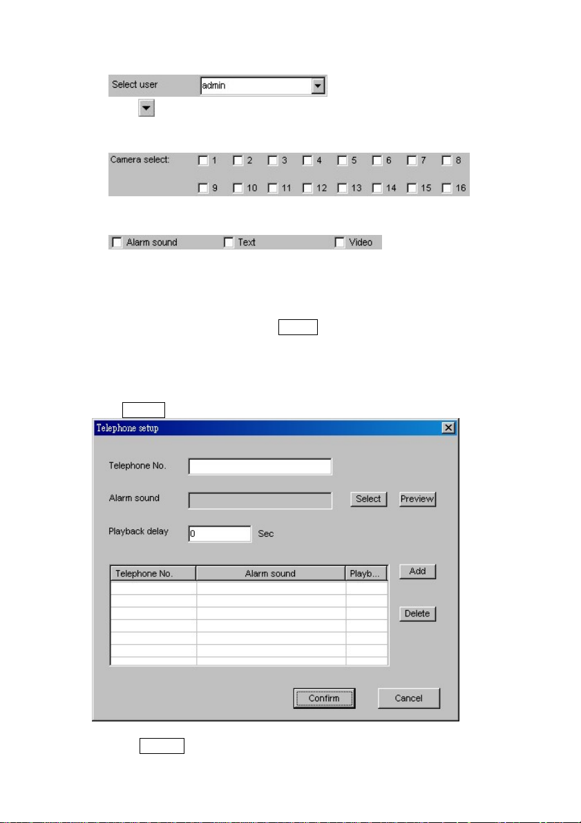
(1) Select the users you want to inform when one alarm event happened
Click to select a user. (If there are some remote SCode Clients using the same
user name to log into this DVR, the alarm inform will be sent to all of them.)
(2) Select the cameras that you want to transfer their living image to the remote sites
Here, it is allowed you to select multiple cameras.
(3) Select the alarm information that you when to send
Alarm sound : You can inform the remote sites to play a preset alarm sound.
Text : Allow the remote site to check the detail information about this alarmed
device.
Video : Send the living video to the remote site.
After finish the above settings, Click Add to add this new remote site into the
alarm inform table. You can inform multiple remote sites at same time.
■ Telephone
If a device is triggered by one event, this function executes the remote alarm function.
It can inform the remote telephone by an alarm sound.
Click Setup to set its action.
(1) Please input the remote telephone’s number.
(2) Click Select button to select one alarm sound.
53 / 143
Page 54

(3) If you want to check the selected sound, please click Preview button.
(4) Input the playback delay time in to control
the starting play time, after the phone is dialed.
After finish the above settings, Click Add to add this new remote phone into the
alarm inform table. You can inform multiple remote sites at same time.
54 / 143
Page 55

Chapter 5 Monitor and Record
Dependent on the number of SCodeSP-5200 capture cards installed, the system will show a
4-, 9- or 16-channel display.
For example, if 4 boards of SP-5200 card are installed, this 16-channel display will appear :
In the Split control panel, it will show the chosen set of channels.
In particular, one can have a single channel displayed and switched to full-display mode.
If 1-split or 4-split mode is active, you can activate the Auto Scan function to scan all
channels one after the other.
5.1 Manual Recording
There are provided 3 ways to execute the manual recording.
1. Execute the recording function to all the channels
Click the below 2 buttons to enable or disable the video recording of all cameras.
< > : Enable the recording of all cameras.
<
> : Stop the recording of all cameras.
2. One by one control
Here can provide 2 ways to enable or disable the recording function, channel by channel.
(1) On-screen command
Click the mouse’s right button at the active image window. You can execute the
Start Record or Stop Record to this active image window.
55 / 143
Page 56

(2) Operating in Video Control Panel
This panel is located in Setup panel of Control panel.
Recording :
In the video panel, each channel has its own control button. You can enable/disable
the recording function, channel by channel.
Not in recording :
5.2 Schedule Recording
The system provides the schedule recording. Before you execute this function, you shall go
to the schedule setup of System Setup to setup the recording schedule. After you finish the
schedule recording table, you can run this function by 32ways. (Please refer to Section 4.6)
(1) Execute it in the schedule setup
Check Enable schedule record which is located in the schedule setup.
(2) Execute it in GUI
Check
to enable or disable the Schedule recording function.
56 / 143
Page 57

5.3 Video Monitoring
1. Zoom
Click twice
(Left button)
Click tw ic e
(Left button)
(1) Use the mouse’s left button
Double click (Left button)
to select the image window you want to enlarge.
This window becomes the activated image window. A white line will be shown around
the borders like the following figure:
(2) Use the mouse’s left button to click the active window twice to enlarge.
2. View / Hide the image
If you want to view or hide the image of a certain camera on the system monitor, go to the
video monitor section of the Video control panel (This panel is located in Setup panel of
Control panel).
View : Hide :
In the video panel, each channel has its own control button. You can view or hide the
image of each channel, one by one.
Note : This setting will not influence its video recording function!
57 / 143
Page 58

5.4 Window Edit
You can rearrange the camera shown in the different image window. It provide 2 ways to do
this function.
1. Use Window editor
Please go into the Camera setup of the System setup. Click
dialog appear.
and the below
For instance, if you want to move Cam16 to Window1, click of Window1 and select
Cam16.
The Cam16’s image will go to Window1 and Cam1 will go to Window16.
2. On screen operation
(1) Activate the window of a camera, which you want to move, to be an active window.
(2) Move the mouse to this active window.
(2) Hold the mouse’s left button and move the mouse to the target window.
(3) Release the mouse and the target camera will jump to the new window.
58 / 143
Page 59

Motion detection Camera Alarm
Enabled :
Disabled :
5.5 Motion Image Detection
In Motion detection section of Alarm page, you can enable or disable the motion-detection
(MOT-DETECT) function of one camera, directly. Each channel has its own control button.
You don’t need to go into the system setup to enable or disable its motion detection function.
Note : If you want to set up the alarm mask in one image window, you shall enable its
motion detection first.
5.6 Camera Alarm
In Camera Alarm section of Alarm page, you can enable or disable the alarm function of one
camera, directly, triggered by image motion detection. Each channel has its own control
button.
You don’t need to go into the system setup to enable or disable its alarm function.
59 / 143
Page 60

5.7 Instant Playback
While in recording, you can play the video immediately without waiting for the video file to
be created. Click the monitor window with the right button of the mouse. You will see a
command window. Select one timing of the Instant playback command and the instant
playback function will be executed.
The system will call the Instant Player program (FPlayer) to play the video.
This instant playback player program has the following operation keys:
■
■
■
■
■
■
■
■ Pull bar
Play : Play the video
Pause : Pause the video
Stop : Stop playing
Skip forward : Jump forward a few seconds
Skip back : Jump back to the start point
Snapshot : Take a picture from the video. The pictures will be saved into :
C:\Program files\SCode\Picture
Close : Quit the instant playback player program
You can move the image playing time from this pull bar directly.
60 / 143
Page 61

■ Zoom
Click the image window with the right button of the mouse. You will see a command
window.
Select one size and the image window will be enlarged.
■ Information window
This window will show the related information of this playing video file.
Window number : C1
Camera name : cam1
Current time : 18:46:32 (Show this image timing)
Start recording time : Start=04/27/2005 18:44:08
61 / 143
Page 62

Chapter 6 Playback
< > to run the playback program.
Image window
Fast search panel
Operation panel Information window
(The Function panel is hidden by )
After this playback program is executed, the Fast search panel goes into All File Search
Mode and automatically lists all video files in the file window, during this day. If there are
no files, this file window will show empty.
This playback program can play multiple video files at the some time.
■
At the right –up corner, there are 2 buttons :
■ (Power off) : Click the button to close the Playback program.
■
(Power off) : Click the button to close the Playback program.
(Minimize) : Click the button to reduce the Playback program to minimum size.
Function panel
File window
62 / 143
Page 63

6.1 File Search
The playback program provides 2 methods to search the stored files:
■ Fast search
■ File search
6.1.1 Fast search
After the playback program launched, it goes into the fast search automatically.
Here, you can search 3 kinds of the files. They are :
■ Search the local recording files
■ Search the imported files
■ Search the remote downloaded files (Only available in SCode Client program)
1.
Local recording files
Here, you can use the below 2 search ways to find the video.
■ Search all files
■ Search the alarmed file
(1)
If you want to search all files created within a specified
time period of one date, < > and input the date
and the time period in the below window.
< > to search video files. The search results will be
listed in the File Window (See the right figure).
Please select the 1 ~ 16 videos from the File Window.
<
Search all files
> to play the selected video files.
63 / 143
Page 64

(2)
In this search, this program will search the today’s files
created by alarm events and listed them in the File Window
(See the right fig.)
If you want to search files created within a specified time
period of the day, <
the time period into the below window.
<
listed in the File Window (See the right figure).
1) Play the videos from the beginning
You can select 1 ~ 16 video files from the File Window.
<
2) Play the video from the alarm points
Please follow the below procedures.
1) Select a video file from the File Window.
2) Click this selected file by the mouse’s right button.
Alarm file search
> and input the date and
> to search video files. The search results will be
> to play the selected video files.
Its Alarm Point Window will appear.
3) Select 1 ~ 16 alarm points and <
4) Click
The playback program will use the multiple windows to play the selected alarm
points in one video file simultaneously.
to play the video.
> to confirm your selection.
64 / 143
Page 65

2.
Search the imported files
Click this button. The system will list all of the imported files in
the File Window.
(1) Play the videos from the beginning
You can select 1 ~ 16 video files from the File Window.
> to play the selected video files.
<
(2) Play the video from the alarm points
1) Select a video file from the File Window.
2) Click this selected file by the mouse’s right button.
Its Alarm Point Window will appear.
3) Select 1 ~ 16 alarm points and <
selection.
4) Click
The playback program will use the multiple windows to play
the selected alarm points in one video file, simultaneously.
to play the video.
> to confirm your
65 / 143
Page 66

6.1.2 Playback modes
This program provides 2 playback modes.
■ Normal mode
■ Frame mode
1. Normal mode
In the mode, you can play 1 ~ 16 different video files, simultaneously.
<
After select the video files from the File window, <
> to select the Normal mode and becomes .
> to play the selected videos.
2. Frame mode
For frame by frame playback of a video file. This playback mode may be used for detail
analysis. You can play 1 ~ 4 video files, recorded in different times, simultaneously.
< > to go to Frame mode and becomes .
After selection of video files from the File window, <
> for playback.
66 / 143
Page 67

The below figures are showing examples of playback of 1, 2, 3, and 4 video files.
Case 1 (1 video) Case 2 (2 videos)
Case 3 (3 videos) Case 4 (4 videos)
After the video files are called out, you can do the following operations.
Playback operation :
(1) <
(2) <
(3) <
(4) <
(5) <
(6) <
Note : From (1) to (6), you can use (Individual control) or (Universal control)
Scroll bar
(1) Select one video first.
(2) Draw the scroll bar’ cursor to an appointed time. Wait a moment and the image will
> : Move to the next group of video pictures.
> : (Continual move mode) Continue to move the group of video pictures.
> : Pause the activated video file.
> : Skip backward the activated video file.
> : Skip forward the activated video file.
> : Stop playing and close the activating video file.
to switch the control mode.
jump to that pointed time to show the video pictures.
67 / 143
Page 68

6.1.3 File search mode
< > to open the File search window . It offers a traditional file search method.
You can search the local files, the imported files, or the remote downloaded files.
: Click this button to find the local files.
: Click this button to find the imported files.
: Click this button to find the remote downloaded file. (Only available in SCode
Client program.)
1. (Search the local files)
This mode is used to search the local recording files.
(1) Search dedicated files
You can input search parameters to search video files within a specified time period.
After set the search parameters, <
will be listed in the File Table.
1) Follow the standard Windows operations to select 1 ~ 16 files from the File Table.
2) < > to confirm the selected video files.
> to search the files. The targeted files
68 / 143
Page 69

3) Go into the playback program window and <
(2) Search all files
< > to search the files. All stored files will be listed in the File Table.
1) Select one or multiple files (1 ~ 16) from the File Table.
2) < > to confirm the selected video files.
3) Go into the playback program window and <
(3) Play the video from the alarmed points
If the video file has a “ ! “ symbol in front of the list, it is a video which has alarm
events happened.
Click the file name, its alarm point window will jump up. You can follow the same
procedure described before to play the video from the alarm points.
(4) Delete files
Follow standard windows operations to select the files and <
(5) Export files
Note : This function shall use Nero program. You must install the Nero program. Its
version shall be V5.9.9 or higher
If you want to export the file to other storage device, after you select the files in the
file table, <
> to execute the export procedure. The below dialog will appear.
> to play the selected video files.
> to play the selected video files.
> to delete.
69 / 143
Page 70

If you want to export the files to other HDD/FDD, enable the HDD/FDD item and set
the path of Export directory. Then, click <
If you want to export the files to CD-R/RW, enable the CD-R/RW item. The system
will use the first CD-R/RW driver as the target driver. Then, click < > to
export those files into the CD-R/RW.
You can export those to HDD/FDD and CD-R/RW at the same time by enabling both
of their items.
(6) Import files
If you want to import the file from outside, < > to execute the import
procedure. The below import dialog will appear.
After select the file and the storage path, you can click <
2. (Search the imported file)
> to export those files.
> to import that file.
70 / 143
Page 71

This mode is used to search the imported files. It will list all of the imported files in the
File table. You can do all of the same operation described in above section.
3.
(Search the remote downloaded file)
This mode is used to search the remote downloaded files files. It will list all of the remote
downloaded files in the File table. You can do all of the same operation described in
above section.
71 / 143
Page 72

6.2 Playback Operation
6.2.1 Playback button
1.
2.
3.
4.
5. (Skip forward) During in playing, skip forward a few seconds.
(Universal / Individual control)
Click this button to set the playback operation keys to work in Universal control mode or
in Individual control mode.
Individual control
When this button is in this status, the playback operations will apply only to one
selected playback window placed in the display.
Universal control
When this button is in this status, the playback operations will be applied to all
playback windows placed in the display, simultaneously.
(Play) Play the video.
(Pause) Pause the video and the video window will keep a still image.
Click to release the pause mode.
(Skip backward) During in playing, jump back a few seconds.
6.
7.
8. Scroll bar
(Step)
Click this button for playback, frame by frame. Click once again to move to the
next frame. Click to leave the Step Play Mode.
(Close file) Click this button to close the video file of the active window.
During playback, draw the cursor of the scroll bar to an appointed time. Wait a moment
for the video to jump to that pointed time to continue with playback.
6.2.2 Video clip
To clip a video section from the playing video.
1. Set the start point
During playback, < > to pin a start point of the clip.
2. Set the end point
After the start point is set, <
> to pin an end point of the clip.
72 / 143
Page 73

3. Save clip
After clipping procedure is done, the below window will pop up. Select the folder to save
the clipped video section.
6.2.3 Speed control button
There are 8 keys to select a playback speed.
1. (1/8-time speed) for 1/8 x the playback speed.
(1/4-time speed) for 1/4 x playback speed.
2.
(1/2-time speed) for 1/2 x playback speed.
3.
(1-time speed) for regular playback speed.
4.
(2-time speed) for 2x the playback speed.
5.
(4-time speed) for 4x the playback speed.
6.
(8-time speed) for 8x the playback speed or as fast the system can offer.
7.
6.2.4 Function buttons
There are 7 function buttons hiden by the key, . You can open or hide them by clicking it.
73 / 143
Page 74

1. : (Mute) Open / Close the audio.
2.
3.
4.
: (Camera information) Show or hide the camera information.
: (Snapshot) Chick this button to take a picture from the active window
: (View pictures) Click this button. The below window will appear.
Select one picture and open it. The Viewer program will show the selected picture.
5. : (Import file) Execute the file import function. (Please refer to the Section 6.3)
6.
7. : (Setup) Call the Setup window. (Please refer to the Section 6.5)
: (File search) Call the file search window. (Please refer to the Section 6.1.3)
74 / 143
Page 75

6.2.5 Zoom
Use the mouse’s left button to click on a video window. You can enlarge the video window
directly.
6.2.6 Video information window
This window shows the below information:
1. Camera number : C1
2. Camera name : cam1
3. Video time : N=00:42:37
4. Played length : P=00:00:01
5. Created date : 2005-5-9
6. Created start time : S=00:42:36
7. Video length : L=01:00:00
8. Stopping record time : E=01:42:38
This window also shows the system’s date and time.
1. System time : 17:20:45
2. System date : 09/05/2005
6.3 Import Files
You can import video files from outside.
>. The below window will appear.
<
After select a file by clicking and the stored folder by clicking , click
to import it.
75 / 143
Page 76

6.4 Export Files
In Fast search mode, you can export videos to an external device or other HDD’s folder.
Note : This function shall use Nero program. You must install the Nero program. Its version
shall be V5.9.9 or higher
1. Search the files from the File Window.
2. <
>. The below window will appear.
You can export the selected files to HDD/FDD, CD-R/RW, or both of them
simultaneously.
(1) If you want to export the files to HDD/FDD, you must set up the export directory.
(2) If you want to export the files to CD-R/RW, the system will identify the system’s 1st
CD-R/WR to be the target driver.
NB : Your DVR system must install the NERO program, version V5.9 or higher.
The related audio file or the Playback program can be sent out simultaneously, while you
export the video files.
: If enabled, the related audio file will be exported.
: If enabled, the playback program will be exported.
76 / 143
Page 77

6.5 System Setup
< > to set up the playback program.
6.5.1 Local video file
This below setup window is used to set a folder for the local recording file when the
program is running in SCode Client program.
6.5.2 Snapshot
The below setup window is used to set a folder for the pictures which are taken in the
playback.
77 / 143
Page 78

6.5.3 Font Color
The below setup window is used to set up the color of the camera information.
If you want to change the font color, please click Select to change it.
6.5.4 Exported file
The below setup window is used to set the targeted HDD’s folder of the export video files.
78 / 143
Page 79

6.5.5 Clipped video file
The below setup window is used to set a folder for clipped video files.
6.5.6 Imported video file
The above tab dialog is used to set a folder for imported video files
79 / 143
Page 80

6.6 Format of File Name
The meaning of video file codes is described below :
Cam1–2004–2–15–23 – 57–17.mfv
Recording date
Year
Date
Month
Video file type
Camera name
Start recording time
Hour
Min.
Sec.
80 / 143
Page 81

Chapter 7 Snapshot
You can take pictures during monitoring, recording and playback. These pictures will be
saved as .BMP format.
7.1 Snapshot
1. In SCode DVR program, < > to take a picture from this active window.
2. In Playback program, <
3. In Instant playback program, <
4. In SCode Client program, <
> to take a picture from this active window.
> to take a picture.
> to take a picture.
7.2 View Pictures
The system uses the Viewer program to view stored pictures.< > and the system will
show the dialog below. Move to the folder where the pictures are stored.
After a picture file is selected, the Viewer program will open the picture file.
81 / 143
Page 82
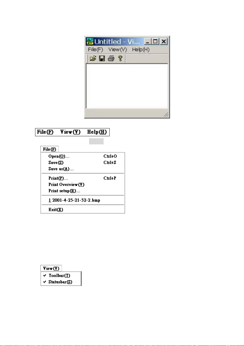
7.3 Viewer Program
■ Command bar
1. File command : Click File(F). The system will show:
- Open : Search and view the picture
- Save : Save the picture
- Save as : Rename the picture name
- Print : Print the picture
- Print Overview : Preview the printing
- Print setup : Printer setup
2. View command : Click it. The system will show:
- Toolbar : Show or hide the Toolbar
- Status bar : Show or hide the status bar
3. Help command : SCode Version description
82 / 143
Page 83

■ Toolbar
: Open
: Save
: Print
: Help
■ Status bar
Shows the working status of the Viewer Program.
■ Zoom (
Move the mouse to
the left button of the mouse and drag the window to the expected size. Then, release the
button.
)
, located at the right-bottom corner of the Viewer window. Hold
83 / 143
Page 84

Chapter 8 PTZ Control
COM port
COM port
You can control a speed dome or PTZ scanner by activating an image window.
RS232/485
Converter
RS232/485
Converter
Scanner Scanner
Speed Dome
Speed Dome
8.1 PTZ Panel
On the PTZ control panel, you can control P, T, and Auto function of a PTZ scanner or a
speed dome. You can click
Here, you can control the below functions:
: (Up) Click and hold this button until the camera reaches the desired position. Then,
release it.
to open or close PTZ panel.
: (Down) Click and hold this button until the camera reaches the desired position. Then,
release it.
: (Left) Click and hold this button until the camera reaches the desired position. Then,
release it.
: (Right) Click and hold this button until the camera reaches the desired position. Then,
release it.
: (Auto scan) Click this button. The plate will turn automatically. Click it again to
stop the auto turn function
84 / 143
Page 85

8.2 Control Panel
In the control panel, there are 2 PTZ pages.
PTZ control (1) PTZ control (2)
You can use
or to change the pages.
8.2.1 PTZ control page (1)
■ IRIS : Click or to adjust the IRIS.
■ FOCUS : Click or to adjust the focus.
■ ZOOM : Click
■ Z-SPEED : Click or to adjust the zooming speed
■ PT-SPEED : Click
■ Other control functions
WIPER : Turn on or off the wiper
LIGHT : Turn on or off the lighter
POWER : Turn on or off the power
HEAT : Turn on or off the heater
COOL : Turn on or off the cooler
or to adjust the zoom.
or to adjust the rotation speed (Pan and tilt)
85 / 143
Page 86

8.2.2 PTZ control page (2)
Here you can control several features.
■
In this panel you can configure the preset-positions of your speed dome.
Click
Preset point of the speed dome
. The panel will go into the preset-point control mode.
Save Run
(1) Go to the preset point:
1) Select one pre-programmed positions and left-click
will turn to that pre-programmed position.
2) If you want to find other pre-programmed positions, click
the page in the dialog and search for the higher or lower numbered preprogrammed positions.
(2) Set your own pre-set positions:
1) Activate the image window of the speed dome.
2) Left-click
3) Move the speed dome to a position that you want to fixate as your preset position.
4) Right-click
■ Auto scan (of the Preset positions)
Speed domes can be set to turn automatically to the preset positions
NB: Please go to the Section 4.7 to see how to program the path of the auto scan.
Click Auto to enable or disable the auto scan function.
■ Output control
Not available in V3.3
■ Input port
Not available in V3.3
(Run), of one the pre-programmed positions.
(Save), to save the position.
Preset point Number
(Run). The speed dome
or to change
86 / 143
Page 87

Chapter 9 eMAP
Click
Click
. The below window will appear.
to close the above window.
9.1 Setup eMAP
Click to open eMAP Setup program.
■ Exit : Click this button to close the eMAP setup program.
87 / 143
Page 88

9.1.1 Create a new MAP
Please follow the below procedure to create a new map.
■ Select the background map
■ Place the devices
■ Save the new map
(1) Select the background map
Click
Select one *.bmp file as the new map’s background map. The select map will be shown
as the below figure.
Note : the Background map shall be BMP format.
to create a new map. The below dialog appears.
88 / 143
Page 89

(2) Place the devices into map
There are 12 kinds of devices.
Icon Select Table
■ Camera
Click this to add a new camera. There are 8 directions of the camera’s icons that you
can choose from the icon select table :
Upwards Downwards Leftwards Rightwards
Left up Left down Right up Right down.
Please follow the below procedure to add a new camera.
1. Click one icon to select it.
2. Move the mouse to the map where you want to put in and click that place. The
select icon will appear at that place.
3. A cursor is flashing and waiting you to input the camera name.
4. After input a name to this camera, press the keyboard’s Enter key to confirm your
input. And the below window will appear.
89 / 143
Page 90

5. Give he camera a device number. This number will equal to the channel number of
the camera stand. Click
For instance, If the camera is assigned to channel 1, its device number = 1.
The camera’s device number shall be 1 ~ 16.
■
■
■
PTZ scanner
Click this to add a new PTZ scanner. There are 8 directions of this device’s icons that
you can choose from the icon select table :
Upwards Downwards Leftwards Rightwards
Left up Left down Right up Right down.
Please follow the procedure described in Camera section to add a new PTZ scanner.
Speed dome
Click this to add a new speed dome. There are 2 directions of this device’s icons that
you can choose from the icon select table :
Upwards Downwards
Please follow the procedure described in Camera section to add a new speed dome.
Sensor
Click this to add a new sensor. Only one device’s icons is in the icon select table.
to select the device number.
Sensor
Please follow the procedure described in Camera section to add a new sensor.
■
■
Output port
Click this to add a new sensor. Only one device’s icons is in the icon select table :
Output port
Please follow the procedure described in Camera section to add a new sensor.
Change background
If you want to change the background map, click this button to change it. The icon
select table will show all the available map which is put in the folder,
C:\Program Files\SCode\initial\bitmap. The available map’s icon is show as below :
*.bmp
Double click the map icon that you want change and the new map will be show on the
background.
90 / 143
Page 91

■
■
■
■
■
■
(3) Device operation
There are 4 device operation buttons.
Add string
If you want to put some notes in the map, click this button. Only one device’s icons is
in the icon select table :
Add text
Please follow the below step to input the note.
(1) Click the above icon, the mouse cursor will become “+”.
(2) Move it to the place that you want to put the note and hold the mouse’s left button
to draw a rectangle.
(3) The cursor will be flash and you can input the text.
(4) After finish the notes, press keyboard’s enter key to confirm your input.
Server : No function in V3.3
DVR : No function in V3.3
Client : No function in V3.3
District : No function in V3.3
Draw line : No function in V3.3
■
■ Copy device
■ Paste device
Device setup
If you want to edit a device’s setting, click this button the setup window will appear.
.
Please finish the setup and click OK to confirm the copy.
If you want to copy a device, select one device and click this button.
After you make a device copy, click this button and move the mouse to the place that
you want to paste the copied device.
Click the map and the copied device icon will appear in map. And then, the setup
dialog will appear as following.
91 / 143
Page 92

Please finish the setup and click OK to confirm the copy.
■ Delete device
If you want to move one device out off the map, select one device and click this
button to delete it.
9.1.2 File operation
There 4 file operation functions.
■
■
■
Create new file : Please refer to Section 9.1.1 for the details
Open file : Click this button to open a existed file.
Save : Click this button to save the changes into the current working file.
92 / 143
Page 93

■
Save as : Click this button to save the map as a new file.
9.2 Open eMAP
Click to open eMAP. The system will call the default eMAP.
Fig 9.2.1
The device icon has 3 kinds of the colors:
■ Gray color : Not in recording state
■ Green color : In recording state
■ Red color : Alarming state
9.2.1 eMAP operation
Click the map by left button. One command dialog will appear.
93 / 143
Page 94

■ Close eMAP : Click this command to close the map.
■ Max eMAP : Click this command to enlarge the map to full image window. (Fig 9.1)
■ Min eMAP : Click this command to reduce the map size as below figure. (Fig 9.2)
Fig 9.2.2
9.2.2 View camera images from eMAP
There are 4 positions in the image window, when you use eMAP to access the device’s
image.
1 1 2 2
3 3 4 4
94 / 143
Page 95

Double click the one device’s icon (Camera, Speed dome, or PTZ scanner) of the eMAP.
The eMAP will reduce to Position 1 and this device’s image will show in the Position 2.
(See the below figure)
1 2
3 4
If you click the 2’nd device, the 1’st device’s image will go to Position 3 and the 2’nd
device’s image will be appeared in Position 2.
(See the below figure)
1 2
3 4
If you click the 3’nd device, the 1’st device’s image will go to Position 4, the 2’nd device’s
image will go to Position 3, and the 3’th device’s image will be appeared in Position 4.
(See the below figure)
1 2
3 4
1 2
3 4
1 2
3 4
95 / 143
Page 96

If you click the 4’th device, the 1’st device’s image will leave the image window, the 2’nd
device’s image will go to Position 4, the 3’th device’s image will be appeared in Position 3,
and the 4’th device’s image will go into position 2.
(See the below figure)
1 2
3 4
1 2
3 4
9.2.3 On-screen command
Click the device icon (Camera, Speed dome, and PTZ scanner). One command dialog will
appear:
You can execute command to execute its function.
(Please refer to the Chapter 3 for details)
96 / 143
Page 97

Chapter 10 Remote Access
10.1 System Introduce
SCode V3.3 RMS (Remote Monitoring System) provides highly sophisticated remote
access capability for small and very large networks. The below figure shown a basic
network structure.
Figure : Basic network structure
There are 4 unites :
■ SCode Server : A machine where the SCode Server program is installed.
■ SCode DVR : A machine where SCode DVR program is installed.
■ SCode Client : A machine where SCode Client program is installed.
■ SCode Central Server : A machine where SCode Client program is installed and
defined as a central server.
NB: When one SCode DVR stands alone, or operates in a small network of DVRs, both the
SCode Server program and SCode Client program can be installed and run
simultaneously on a single computer.
10.2 SCode RMS Installation
1. Install SCode Server Program
(1) Insert the SCode installation disc into the CD drive.
(2) Execute \SCode_RMS\SCodeV33_Server_EN.exe
Or Execute \SCode_RMS\SCodeV33_Server_DE.exe (German version)
(3) Follow the setup instructions to finish the SCode_Server program’s installation.
2. Install SCode Client Program
(1) Insert the SCode installation disc into the CD drive.
(2) Execute \SCode_RMS\SCodeV33_Client_EN.exe
Or Execute \SCode_RMS\SCodeV33_Client_DE.exe (German version)
(3) Then, follow the instructions of the setup program to finish the SCode_Client
program’s installation.
97 / 143
Page 98

10.3 SCode Network Structure
SCode RMS supports a multi-server and a central server structure.
■ Basic network structure
Figure 10.3.1 describes a basic network structure. All of the SCode DVR machines and
SCode Client machines are linked to one SCode Server. The network shall support
TCP/IP and UDP/IP. The SCode Server will send all the linking information of SCode
DVRs to all SCode Clients.
Figure 10.3.1 Basic network structure
One SCode Client can access multiple SCode DVRs simultaneously.
And one SCode DVR can be accessed by multiple SCode Clients, simultaneously.
■ Multi-server structure
One SCode Client can access multiple SCode Servers, simultaneously.
Figure 10.3.2 Multi-server structure
SCode Client can access SCode DVRs which is located inside of every SCode Server.
98 / 143
Page 99

■ Central-server structure
SCode Server can link up to a SCode Central Serve.
Figure 10.3.3 Central server structure
SCode Client can access SCode Central Server and this central server will send all the
networking information to all of SCode Clients which are linked to the central server.
10.4 SCode Server
One SCode Server has 2 kinds of IP addresses:
■ Internal IP address : The Server that links with an internal network.
■ External IP address : The Server that links with an external network.
1. If one SCode Server is a gateway between 2 networks, its internal IP and external IP are
different.
2. If one SCode Server does not link with an external network, It only has one IP address.
99 / 143
Page 100

10.4.1 Examples
Example 1 :
DVR 1
DVR 3
DVR 2
LAN 1
Client 1
Internal
IP 1
External
IP 1
External
Network
Sever1
Client 3
External
IP 2
Internal
IP 2
Sever 2
There are 3 SCode DVRs and 3 SCode Clients, loacted in different places.
(1) For SCode DVR
DVR1 links to the internal IP of Server 1 .
DVR2 links to the internal IP of Server 2 .
DVR 3 can link to the external IP of Server 1 or Server 2.
(2) For SCode Client
Client1 links to the internal IP of Server 1. (Use the local link)
Client2 links to the internal IP of Server 2. (Use the local link)
Client3 can link to the external IP of Server 1 and Server 2, simultaneously. (Use the
Local link)
Example 2 :
DVR 1
Sever1
External
IP 1
External
Network
LAN 2
Internal
IP 1
LAN 1
(1) For SCode Client
Client1 can link to the external IP of Server 1. (Use the remote link)
LAN 2
Client 2
Client 1
100 / 143
 Loading...