


Electric Pumps
Instruction Manual
MODELS: PE0501T, PE1002T, PE1503T, PE1505T, PE3005T
PEW0501T, PEW1002T, PEW1503T, PEW1505T, PEW3005T
SFA Companies 10939 N. Pomona Ave. Kansas City, MO 64153
Tel: 888-332-6419 * Fax: 816-891-6599
E-mail: sales@bvahydraulics.com Website: www.bvahydraulics.com
Maximum Operating Pressure 10,000 PSI
(for single acting applications only)
PE0501T-M0 122011
Model PE0501T
Model PE1002T, PE1503T
This is the safety alert symbol. It is used to alert you to potential personal injury hazards.
!
Obey all safety messages that follow this symbol to avoid possible injury or death.
Model PEW0501T
Model PEW1002T, PEW1503T
Printed in Taiwan

SAFETY AND GENERAL INFORMATION
Save these instructions. For your safety, read and understand the information contained within. The owner and operator shall
have an understanding of this product and safe operating procedures before attempting to use this product. Instructions and
safety information shall be conveyed in operator's native language before use of this product is authorized. Make certain that the
operator thoroughly understands the inherent dangers associated with the use and misuse of the product. If any doubt exists as
to the safe and proper use of this product as outlined in this factory authorized manual, remove from service immediately.
Inspect before each use. It is recommended that, prior to each use, an inspection be done by qualied personnel and that any
missing or damaged parts, decals, warning / safety labels or signs be replaced with factory authorized replacement parts only. Any
pump that appears to be damaged in any way, is worn, leaking or operates abnormally shall be removed from service immediately
until such time as repairs can be made. Any pump that has been subjected to a shock load (a load dropped suddenly, causing
the system pressure to exceed 10,000 PSI), shall be removed from service immediately until checked by qualied personnel.
Owners and operators of this equipment shall be aware that the use and subsequent repair of this equipment does require special
training and knowledge.
PRODUCT DESCRIPTION
This Pump is engineered to meet most industrial standards for Performance and Safety. Its allows quick displacement of hy-
draulic uid under no load conditions and easy pumping in loaded conditions. This electric hydraulic pump supplies compressed
hydraulic uid to compatible single acting applications ONLY. Such applications include rams, presses, spreaders, compactors
and crimping machines, anywhere that 10,000 PSI of single acting uid pressure is needed. Special skill, knowledge and training
may be required for a specic task and the product may not be suitable for all the jobs described above. Unsuitable applications
would include applications that call for a device to move, level or support persons, animals, hazardous materials, mobile homes/
dwellings in general, mirrors and/or plate glass, and/or to connect/secure hatches, components, etc. between bulkheads. The
user must make the decision regarding suitability of the product for any given task and assume the responsibility of safety for
himself/herself and others in the work area.
! DANGER
TO AVOID ELECTROCUTION HAZARD:
• Owner, Operator must read, understand and follow all printed material provided with this device before use.
• Connect ONLY to properly grounded electrical source. Connect to GFI outlet ONLY! For use in dry locations.
• Avoid the use of extension cords. If necessary, for extension cords lengths up to 25 ft, use SJT-14X3 or heavier.
For cords up to 50 ft, use SJT-12X3 or heavier. For extension cord lengths up to 100 ft, use SJT-10X3 or heavier
NEVER use a 3 prong adapter.
• Do not operate this device in an explosive atmosphere or in the presence of conductive liquids.
2

Electric Motor
Control Valve
Control
Valve Lever
Oil Output
Ports
Drain Plug
Control
Box
Electric Motor
ON/OFF Switch
Vent Cap
Reservoir
Power Cord
Valve Lever
Oil Output
Ports
Carry
Handle
Drain Plug
Electric
Motor
Control
Remote ON/
OFF Switch
Control
Box
Oil Filler/
Vent Cap
Reservoir
Power Cord
Figure 1 - Typical 3-way 3-position PE
series Electric Pump Components
(PE1002T shown)
Model Number
(for use w/
single acting
cylinder)
PE0501T
PE1002T
PE1503T
PE1505T
PE3005T
PEW0501T
PEW1002T
PEW1503T
PEW1505T
Figure 2 - Typical -way 3-position PEW series
Electric Pump Components (PEW1002T
shown)
SPECIFICATIONS
Usable
Oil
Capacity
(gal)
1 650
2 600 397 36 1 63
3 650
5 800 94
5 650 592 110 3.0 230 101
1 350 293 18 0.5
2 600 366 37 1 73
3 650 488
5 800 475 96
Pressure Rating
(psi)
1st
Stage
2nd
Stage
10,000
Output Flow Rate
(in3/min)
1st
Stage
293 18
476 61 1.5
2nd
Stage
61 1.5
Valve
Type
3-way,
3-position
Valve
Function
Advance/
Hold/
Run
Motor
(hp)
0.5
Motor
Voltage
(V)
115
115
Weight
(lbs)
57
77
59.5
77
PEW3005T
5 420 592 110 3.0 230 110
3
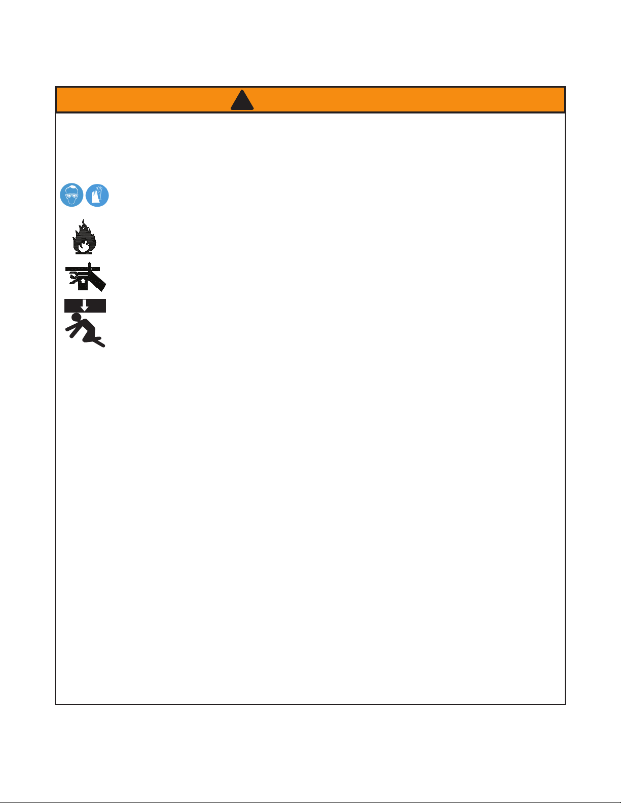
! WARNING
• Read, understand, and follow all instructions provided with
and on this device before use.
• All WARNING statements must be carefully observed to
help prevent personal injury.
• No alteration shall be made to this device.
• Always wear protective gear when operating
hydraulic equipment. Tie up long hair, wear
eye and ear protection, and non slip foot
wear.
• Keep hydraulic equipment away from ames
and heat. Hydraulic uid can ignite and burn.
Do not operate if leaks are detected.
•
Crush Hazard. Keep hands and feet away
from loading area. Avoid pinch points or
crush points that can be created by the load,
cylinder, or system components.
•
To avoid crushing and related injuries:
NEVER work on, under or around a lifted
load before it is supported by appropriate
mechanical means. Never rely on hydraulic
pressure alone to support load.
HYDRAULIC PUMPS
•
The user must be a qualied operator familiar with the
correct operation, maintenance, and use of pumps. Lack
of knowledge in any of these areas can lead to personal
injury.
• Do not exceed rated capacity of the pump or any equipment
in the system.
• Never attempt to lift a load weighing more than the capacity
of the output device (cylinder, spreader etc.)
• Do not subject pump and its components to shock loads.
• Burst hazard exists if hose or connection pressure exceeds
rated pressure.
•
Inspect pump, cylinder, hoses and connections before each
use to prevent unsafe conditions from developing. Do not
use if they are damaged, altered or in poor condition. Do
not operate the system with bent or damaged coupler or
damaged threads.
• Never hold or stand directly in line with any hydraulic
connections while pressurizing.
• ALWAYS
verify load.
• Never attempt to disconnect hydraulic connections
under pressure. Release all line pressure before
disconnecting hoses.
• Use of incorrect power source will damage the motor.
• Do not use an ungrounded (two-prong) extension cord.
• Do not install, remove or rewire the motor with power
applied. Have qualied technician to install, adjust and
service the motor.
use gauge or other load measuring instrument to
• Do not operate this device in an extreme temperature,
explosive atmosphere or in the presence of conductive
liquids.
• Always inspect hoses and connections for damage prior
to use.
• Ensure the device is placed on a hard, level surface.
• Ensure that application is stable to work on and around.
•
Use only approved accessories and approved hydraulic
uid.
•
Never attach ANY component not authorized by
manufacturer.
• Do not connect to application which can return more oil to
the reservoir than the pump reservoir can hold.
• Do not connect pump to hydraulic system powered by
another pump.
• This device is not suitable for use as support device! As
the system load is lifted, use blocking and cribbing to
guard against a falling load.
• All personnel must be clear before lowering load or
depressurizing the system.
• Never try to disassemble a hydraulic pump, refer repairs
to qualied, authorized personnel.
HYDRAULIC HOSES & FLUID TRANSMISSION LINES
• Avoid short runs of straight line tubing. Straight line runs
do not provide for expansion and contraction due to
pressure and/or temperature changes.
• Reduce stress in tube lines. Long tubing runs should
be supported by brackets or clips. Before operating
the pump, tighten all hose connections with proper
tools. Do not overtighten. Connections should only be
tightened securely and leak-free. Overtightening can
cause premature thread failure or high pressure ttings
to burst.
• Should a hydraulic hose ever rupture, burst or need to
be disconnected, immediately shut off the pump and
release all pressure. Never attempt to grasp a leaking
pressurized hose with your hands. The force of escaping
hydraulic uid can inict injury.
• Do not subject the hose to potential hazard such as re,
sharp objects, extreme heat or cold, or heavy impact.
• Do not allow the hose to kink, twist, curl, crush, cut or bend
so tightly that the uid ow within the hose is blocked or
reduced. Periodically inspect the hose for wear.
• Do not pull, position or move setup by the hose.
•
Hose material and coupler seals must be compatible with
hydraulic uid used. Hoses also must not come in contact
with corrosive materials such as battery acid, creosoteimpregnated objects and wet paint. Never paint a coupler
or hose.
•
FAILURE TO HEED THESE WARNINGS MAY RESULT
IN PERSONAL INJURY AS WELL AS PROPERTY
DAMAGE.
4

BEFORE USE
Read, understand, and follow all printed materials carefully
before attempting to assemble or operate these pumps.
NOTICE: E-Pumps are shipped dry. Add oil before use.
Electrical Connections:
Compare motor nameplate against power availability
to prevent motor burnout and dangerous electrical
overloading. The motors are wired for 110-125 volts unless
otherwise specied.
DANGER: Motor, connections and remote on/off switch
!
are energized components containing line voltage.
Ensure supply is grounded and GFI protected.
Hydraulic Connections:
1. Make sure to use the hydraulic oil specified by the
manufacturer. Ensure oil level in reservoir is ~ 2" from top
of reservoir plate, with cylinders retracted and motor off.
2. Use of pressure gauge is strongly recommended. Attach a
pressure gauge between the pump and cylinder to monitor
pressure on cylinder.
3. Make sure coupler, hose, valve, gauge are tighten securely
to prevent accidental removal of components while in use.
Hoses must not be kinked or twisted.
NOTICE: Always secure threaded port connections with non-
hardening pipe thread compound. Take care not to introduce
compound into port orices.
To ensure smooth operation, bleed air from the system by fully
advancing and retracting the cylinder several times.
4. Do not exceed the rated capacity of the equipment connected
to the pump. Ensure that all hydraulic equipment used
with this pump is rated at 10,000 psi or greater.
OPERATION
1. Check oil level, add oil if necessary.
2. Make sure system ttings and connections are tight and
leak free.
3. Place control valve lever in the middle (Neutral/Hold)
position to prevent accidental lifting or moving of load.
4. To start the motor: Toggle the ON/OFF switch located on
the control box to 'ON' position OR for momentary use:
Leave control box switch in the 'OFF' position and toggle
remote ON/OFF pendant switch.
5. It is recommended to use to ON/OFF switch at the control
box to let the pump idle for a few minutes before putting
into operation.
WARNING: This pump is for use with a single acting
!
cylinder ONLY! Connect one hose from either pump
oil output port to the input port of a single acting
application such as a cylinder. Block the unused output
port securely. This model can not be used with double
acting cylinders.
6. Use the control valve lever to control the direction of uid
ow. These pumps are equipped with a 3-way 3-position
valve for use with single acting cylinder applications ONLY.
Refer to Figure 3 below for the ow path.
7. Always monitor the pressure, load and position.
8. Do not exceed the rated capacity of the equipment
connected to the pump. To reduce system component
stress, material fatigue, and the risk of personal injury
and property damage, never load a hydraulic application
(cylinder, spreader, etc.) to more than 80% of its rated
capacity.
9. Shift the control valve until the desired pressure, load or
position is reached. Note: Do not continue to operate pump
after cylinder plunger is fully extended or retracted.
10. To turn off the motor: Toggle the ON/OFF switch on the
control box to 'OFF' position.
11. Depressurize all connections before disconnect. If you
have any questions, call BVA Technical Service @ (888)332-6419.
WARNING: ALWAYS monitor pressure, force and load
!
position. Pressure may be monitored by means of an
optional manifold and gauge. Force may be monitored
by means of a load cell and digital indicator. Correct
application position can only be determined by the
operator of the equipment.
Port A
Position 1 (Advance):
Pressured oil ows to port A.
Port A
2
1
Figure 3- Schematic ow path, valve position of 3-way, 3-position valve for Single Acting Cylinder
3
Port B
P T
5
Port A
P T
Position 2 (Hold):
Neutral, ports A is
closed. Hold Position.
Port A
P T
Position 3 (Retract):
Port A returns ow to
tank.

TROUBLESHOOTING
A system failure may or may not be the result of a pump malfunction. The following information is intended to be used as an
aid in determining if a problem exists. Pumps should be repaired only be repaired by authorized BVA Service Center.
Symptom Possible Causes Corrective Action
• No power or wrong voltage
Motor will not start
Erratic cylinder action
Pump fails to maintain
pressure
Cylinder extends partially
Cylinder moves slower than normal
Cylinder leaks hydraulic uid • Worn or damaged seals • Replace cylinder
Cylinder will not retract or
retracts slower than normal
Motor cuts out
• Damaged power cord
• Tripped circuit breaker
• Loose or faulty wiring
• Air in system or pump cavitation
• External leak
• Internal hydraulic leak
• External leak
• Internal hydraulic leak
• Pump or valve malfunction
• Hydraulic oil level too low in pump
• Load is above the capacity of system
• Cylinder is sticking or binding
• Loose connection or coupler
• Restricted hydraulic line or tting
• Pump not working correctly
• Cylinder seals leaking
• Loose couplers
• Weak or broken retraction springs
• Cylinder damaged internally
• Pump reservoir too full
• Extension cord too long
• Faulty motor
• Overheated motor trips circuit breaker
• Check the power supply & voltage
• Contact Customer Service
• Ensure electrical supply is adequate
• Contact Customer Service
• Follow pump instructions for bleeding air
• Tighten all connections
• Contact Service Center
• Tighten all connections
• Contact Service Center
• Fill and bleed the system
• Use the correct equipment
• Contact Service Center
• Tighten
• Clean and replace if damaged
• Check pump operating instructions
• Replace cylinder
• Tighten couplers
• Replace cylinder
• Replace cylinder
• Drain hydraulic uid to correct level
• Replace
• Replace or repair
• Allow motor to cool, reset circuit breaker
MAINTENANCE
1. Keep areas around pump unobstructed in order to provide
good air ow around the motor and pump. Try keep the
motor and pump as clean as possible.
2. Inspect hoses and connections daily. Replace damaged
components immediately with BVA Hydraulics
replacement parts only.
3. Tighten connections as needed. Use non-hardening pipe
thread compound when servicing connections.
4. Check hydraulic oil level every 40 hours of operation. Add
hydraulic oil if necessary.
5. Completely change the hydraulic oil every 300 hours of
operation. Change the oil more frequently when pump is
used in an extremely dusty environment or when the oil has
been overheated. Use only good quality hydraulic oil. We
recommend BVA hydraulic oil (F01 & F05), Mobil DTE 15M
or equivalent. To order the oil, refer to service parts section.
Use only the manufacturers recommended hydraulic oil.
Use of other hydraulic oil may result in pump failure
and will void warranty.
Adding Hydraulic Oil
1. Make sure electric motor is OFF.
2. Depressurize and disconnect hydraulic hose from
application.
3. Remove vent cap on the top plate of the reservoir.
4. Use a funnel to ll reservoir to about 2" from top of reservoir
plate.
5. Wipe up any spilled uid and reinstall the vent cap.
Changing Hydraulic Oil
1. For best results, change hydraulic oil once a year.
2. Remove drain plug, tilt the pump then pour used uid into
a sealable container.
3. Dispos e the hydraulic oil in accordan ce with local
regulations.
4. Fill hydraulic oil, then reinstall vent cap.
Cleaning
Clean oil lter screen periodically with nonammable solvent,
then blow dry before reassemble back to pump.
Storage
1. When not in use, depressurize and disconnect hydraulic
hoses from application.
2. Wipe clean, thoroughly.
3. Store in clean, dry environment. Avoid temperature
extremes.
4. For transportation or long term storage, shield pump with
a protective cover.
6

Electric Pumps
25
23
22
21
20
19
18
17
16
15
14
13
12
24
11
10
9
8
7
6
5
4
3
2
26
1
Service Parts
INCLUDES MODEL NUMBERS:
PE0501T & PEW0501T
SFA Companies 10939 N. Pomona Ave. Kansas City, MO 64153
Tel: 888-332-6419 * Fax: 816-891-6599
E-mail: sales@bvahydraulics.com Website: www.bvahydraulics.com
Not all components of the pump are replacement items, but are illustrated as a convenient reference of location and position in
the assembly sequence.
Parts List
Item Part No. Description Qty.
1 E06-4-9000-108 Motor, 0.5 HP (PE0501T) 1
E06-4-9001-100 Motor (PEW0501T)
2 E05-6-9002-107 Gasket, Motor 1
3 E05-6-9003-109 Reservoir Cover Plate 1
4 E05-6-9004-101 Reservoir Gasket 1
5 E05-4-3000-101 Upper Plate Assembly 1
6 E05-6-9006-105 Eccentric 5/8" Shaft 1
7 622-6-0318-203 Bearing 1
8 E05-6-9007-107 Sleeve Eccentric Bearing 1
9(a) E05-4-4000-106 Piston Manifold 2
10 511-7-0064-109 O-ring 2
11 E05-4-5000-101 Lower Plate Assembly 1
12 E05-4-2000-106 Oil Cap 1
13(b) 649-1-0060-407 Bolt, M6 10
14(b) 601-3-0064-106 Washer 10
15(c,d) PW4 Control Valve, 4-way 1
16 649-1-0095-204 Socket Head Screw 4
17(e) E05-4-8000-106 Manifold, Safety Valve 1
18 649-1-0063-403 Hex Head Bolt 4
19(f) E05-4-6000-106 Gear Pump Assy, 1/2 HP 1
20 H23-6-1000-102 Magnet 1
21 E05-3-9005-105 Reservoir 1
22(g) 532-3-0160-104 Special Washer 1
23(g) E05-6-8008-104 Parker Hex Plug 1
24 E05-3-7000-105 Handle Weldment 1
25 E11-6-3005-103 Drain Line 1
26 PEW01 Remote Pendant 1
(a) E05-3-9940-102 Piston Blk Assy Repair Kit (b) E05-3-9902-105 Reservoir Repair Kit (c) E05-3-9911-106 Valve Assy Repair Kit (d) E05-3-9910-104 Valve Assy Bolt Repair Kit (e) E05-3-9980-105 Manifold Repair Kit -
(f) E05-3-9960-109 Gear Pump Repair Kit -
(g) E05-3-9901-103 Hex Plug Repair Kit -
-- F01 BVA Hydraulic Oil, 1 gal -
7

Electric Pumps
24
23
22
21
20
19
18
17
16
15
14
13
11
12
10
9
8
7
6
5
4
3
2
25
1
Service Parts
INCLUDES MODEL NUMBERS:
PE1002T & PEW1002T
SFA Companies 10939 N. Pomona Ave. Kansas City, MO 64153
Tel: 888-332-6419 * Fax: 816-891-6599
E-mail: sales@bvahydraulics.com Website: www.bvahydraulics.com
Not all components of the pump are replacement items, but are illustrated as a convenient reference of location and position in
the assembly sequence.
Parts List
Item Part No. Description Qty.
1 E11-4-9000-101 Motor, 1.0 HP (PE1002T) 1
E11-4-9001-103 Motor (PEW1002T)
2 E05-6-9002-107 Gasket, Motor 1
3 E10-6-9003-102 Reservoir Cover Plate 1
4 E05-6-9004-101 Reservoir Gasket 1
5 E05-4-3000-101 Upper Plate Assembly 1
6 E05-6-9006-105 Eccentric 5/8" Shaft 1
7 622-6-0318-203 Bearing 1
8 E05-6-9007-107 Sleeve Eccentric Bearing 1
9(a) E10-4-4000-109 Piston Manifold 2
10 511-7-0064-109 O-ring 2
11 E05-4-5000-101 Lower Plate Assembly 1
12 E10-4-2000-109 Adapter Assy 1
13(b) 649-1-0060-407 Bolt, M6 10
14(b) 601-3-0064-106 Gasket 10
15(c,d) PW4 Control Valve, 4-way 1
16 649-1-0095-204 Socket Head Cap Screw 4
17(e) E05-4-8000-106 Manifold, Safety Valve 1
18 649-1-0063-403 Hex Head Bolt 4
19(f) E05-4-6001-108 Gear Pump Assy 1
20 H23-6-1000-102 Magnet 1
21 E10-3-9005-108 Reservoir 1
22(g) 532-3-0160-104 Special Washer 1
23(g) E05-6-8008-104 Parker Hex Plug 1
24 E11-6-3006-105 Drain Line 1
25 PEW01 Remote Pendant 1
(a) E05-3-9940-102 Seal Kit for Item #9 (b) E05-3-9902-105 Reservoir Bolt Repair Kit (c) E05-3-9911-106 Valve Assy Repair Kit (d) E05-3-9910-104 Valve Assy Bolt Repair Kit (e) E05-3-9980-105 Seal Kit for Item #17 (f) E05-3-9960-109 Seal Kit for Item #19 (g) E05-3-9901-103 Parker Hex Plug Repair Kit -
-- F01 BVA Hydraulic Oil, 1 gal -
-- F05 BVA Hydraulic Oil, 5 gal -
8

2
3
4
5
6
7
8
9
10
11
12
23
22
21
20
19
18
17
24
16
15
14
13
1
25
Electric Pumps
Service Parts
INCLUDES MODEL NUMBERS:
PE1503T, PE1505T, PEW1503T & PEW1505T
SFA Companies 10939 N. Pomona Ave. Kansas City, MO 64153
Tel: 888-332-6419 * Fax: 816-891-6599
E-mail: sales@bvahydraulics.com Website: www.bvahydraulics.com
Not all components of the pump are replacement items, but are illustrated as a convenient reference of location and position in
the assembly sequence.
Parts List
Item Part No. Description Qty.
1 E16-4-9000-106 Motor, 1.5 HP (PE models) 1
E16-4-9001-108 Motor (PEW models)
2 E05-6-9002-107 Gasket, Motor 1
3 E10-6-9003-102 Reservoir Cover Plate 1
4 E05-6-9004-101 Reservoir Gasket 1
5 E15-4-3000-109 Upper Plate Assembly 1
6 E05-6-9006-105 Eccentric 5/8" Shaft 1
7 622-6-0318-203 Bearing 1
8 E05-6-9007-107 Sleeve Eccentric Bearing 1
9(a) E15-4-4000-104 Piston Manifold 4
10 511-7-0064-109 O-ring 2
11 E15-4-5000-109 Lower Plate Assembly 1
12 E10-4-2000-109 Vent Cap 1
13(b) 649-1-0060-407 Bolt, M6 10
14(b) 601-3-0064-106 Washer 10
15(c,d) E05-4-1000-101 Control Valve, 4-way 1
16 649-1-0095-204 Socket Head Screw 4
17(e) E05-4-8000-106 Manifold, Safety Valve 1
18 649-1-0063-403 Socket Head Cap Screw 8
19(f) E15-4-6000-104 Gear Pump Assy (1503) 1
19(f) E15-4-6002-108 Gear Pump Assy (1505) 1
20 H23-6-1000-102 Magnet 1
21 E15-3-9005-104 Reservoir 1
22(g) 532-3-0160-104 Drain Plug Assembly 1
23(g) E05-6-8008-104 Filter 1
24 E11-6-3008-109 Drain Line 1
25 PEW01 Remote Pendant 1
(a) E15-3-9940-101 Piston Blk Assy Repair Kit (b) E05-3-9902-105 Reservoir Bolt Repair Kit (c) E05-3-9911-106 Valve Assy Repair Kit (d) E05-3-9910-104 Valve Assy Bolt Repair Kit (e) E05-3-9980-105 Manifold Assy Repair Kit -
(f) E15-3-9960-107 Gear Pump Repair Kit -
(g) E05-3-9901-103 Parker Hex Plug Repair Kit -
-- F01 BVA Hydraulic Oil, 1 gal -
-- F05 BVA Hydraulic Oil, 5 gal -
9

Electric Pumps
24
25
2
13
23
22
20
21
19
18
17
16
15
14
12
11
10
9
8
7
6
5
4
3
1
Service Parts
INCLUDES MODEL NUMBERS:
PE3005T & PEW3005T
SFA Companies 10939 N. Pomona Ave. Kansas City, MO 64153
Tel: 888-332-6419 * Fax: 816-891-6599
E-mail: sales@bvahydraulics.com Website: www.bvahydraulics.com
Not all components of the pump are replacement items, but are illustrated as a convenient reference of location and position in
the assembly sequence.
Parts List
Item Part No. Description Qty.
1 E30-4-9003-106 Motor, 3 hp (PE3005) 1
E30-4-9001-102 Motor (PEW3005)
2 E05-6-9002-107 Gasket, Motor 1
3 E10-6-9003-102 Reservoir Cover 1
4 E05-6-9004-101 Reservoir Gasket 1
5 E30-4-3000-100 Upper Plate Assembly 1
6 E30-6-9006-104 Eccentric 5/8" Shaft 1
7 622-6-0318-203 Bearing 1
8 E05-6-9007-107 Sleeve Eccentric Bearing 1
9(a) E30-4-4000-105 Piston Manifold 4
10 511-7-0064-109 O-ring 2
11 E30-4-5000-100 Lower Plate Assembly 1
12 E10-4-2000-109 Adapter Assembly 1
13(b) 649-1-0060-407 Bolt 10
14(b) 601-3-0064-106 Gasket 10
15(c,d) E05-4-1000-101 Control Valve, 4-way 1
16 649-1-0095-204 Socket Head Cap Screw 4
17(e) E05-4-8000-106 Manifold, Safety Valve 1
18 649-1-0063-403 Socket Head Cap Screw 8
19(f) E30-4-6000-105 Gear Pump Assembly 1
20 H23-6-1000-102 Magnet 1
21 E30-3-9005-104 Reservoir 1
22(g) 532-3-0160-104 Drain Plug Washer 1
23(g) E05-6-8008-104 Hex Plug 1
24 E11-6-3008-109 Drain Line 1
25 PEW01 Remote Pendant 1
(a) E15-3-9940-101 Piston Blk Assy Repair Kit (b) E05-3-9902-105 Reservoir Bolt Repair Kit (c) E05-3-9911-106 Valve Assy Repair Kit (d) E05-3-9980-104 Valve Assy Bolt Repair Kit (e) E05-3-9910-105 Manifold Assy Repair Kit -
(f) E15-3-9960-107 Gear Pump Repair Kit -
(g) E05-3-9901-103 Parker Hex Plug Repair Kit -
-- F01 BVA Hydraulic Oil, 1 gal -
-- F05 BVA Hydraulic Oil, 5 gal -
10

SFA Companies
10939 N. Pomona Ave. Kansas City, MO 64153
Tel: 888-332-6419
E-mail: sales@bvahydraulics.com
11

LIMITED LIFETIME WARRANTY
BVA Hydraulics®, represented in the United States by SFA Companies [“SFA”] warrants this product to be free from defects in
material and workmanship for the life of the product as long as the original purchaser owns the product. The warranty is nontransferable and is subject to the terms, exclusions, and limitations described below:
• Damaged components, including but not limited to bent rams, dented or crushed cylinder walls, broken welds or couplers as
well as worn out seals, o-rings and springs are the result of misuse and not covered by warranty and BVA Hydraulics will not
provide any warranty credit for such damaged components.
• This warranty does not cover ordinary wear and tear, overloading, alterations (including repairs or attempted repairs not
performed by BVA Hydraulics or one of its authorized personnel), improper uid use, or use of the product in any manner for
which the product was not intended or the use of which is not in accordance with the instructions or warnings provided with
the product.
• In the unlikely event that a BVA Hydraulics product fails due to material defect in workmanship, you may contact SFA for disposition. In such cases, the customer’s sole and exclusive remedy for any breach or alleged breach of warranty is limited to
the repair or replacement of the defective product.
• Under no circumstances is BVA Hydraulics liable for any consequential or incidental damage or loss whatsoever.
• THIS WARRANTY IS LIMITED TO NEW PRODUCTS SOLD THROUGH AUTHORIZED DISTRIBUTORS AND OTHER CHANNELS DESIGNATED BY BVA HYDRAULICS. NO AGENT, EMPLOYEE OR OTHER REPRESENTATIVE OF BVA HYDRAULICS IS AUTHORIZED TO MODIFY THIS WARRANTY.
• THE FOREGOING IS EXCLUSIVE AND IS IN LIEU OF ALL OTHER EXPRESS AND IMPLIED WARRANTIES, INCLUDING
BUT NOT LIMITED TO THE IMPLIED WARRANTIES OF MERCHANTABILITY AND FOR A FITNESS FOR A PARTICULAR
PURPOSE.
• Components not manufactured by BVA Hydraulics including certain motor systems, gasoline engines, and other are not
covered by this warranty and instead are covered by the manufacturer’s separate manufacturer’s warranty provided in the
package.
• BVA Hydraulics’ liability in all cases is limited to, and will not exceed the purchase price paid for the product.
SFA Companies
10939 N. Pomona Ave. Kansas City, MO 64153
Tel: 888-332-6419
E-mail: sales@bvahydraulics.com
 Loading...