

BVA Hydraulics PEW0501, PEW1002, PEW1503, PEW3005 User Manual

Electric Pumps
Instruction Manual
INCLUDES MODEL NUMBERS:
PE0501, PE1002, PE1503, PE3005,
PEW0501, PEW1002, PEW1503 & PEW3005
SFA Companies 10939 N. Pomona Ave. Kansas City, MO 64153
Tel: 888-332-6419 * Fax: 816-891-6599
E-mail: sales@bvahydraulics.com Website: www.bvahydraulics.com
PE0501-M0
Ver. 4.0 © 2006
Model No. PE0501
Model No. PE1002, PE1503 & PE3005
Model No.PEW0501
Model No. PEW1002, PEW1503 & PEW3005
Printed in Taiwan
Save these instructions. For your safety, read and understand the information contained within. The owner and
Drawn
operator shall have an understanding of this product and safe operating procedures before attempting to use this
product. Make certain that the operator thoroughly understands the inherent dangers associated with the use and
misuse of the product. If any doubt exists as to the safe and proper use of this product as outlined in this factory
authorized manual, remove from service immediately.
Inspect before each use. It is recommended that, prior to each use, an inspection be done by qualified personnel
and that any missing or damaged parts, decals, warning / safety labels or signs be replaced with factory authorized
replacement parts only. Any pump that appears to be damaged in any way, is worn, leaking or operates abnormally
shall be removed from service immediately until such time as repairs can be made. Any pump that has been or
suspected to have been subject to a shock load (a load dropped suddenly, causing the system pressure to exceed
10,000 PSI), shall be removed from service immediately until checked by qualified personnel. Owners and operators
of this equipment shall be aware that the use and subsequent repair of this equipment may require special training and
knowledge. Labels and owners manuals are available from the manufacturer (see Service Parts pages 8 thru 11).
PRODUCT DESCRIPTION
BVA Hydraulics Electric Pumps are engineered to meet or exceed ANSI B30.1 Standards for Performance and Safety.
Its unique hydraulic circuit allows quick displacement of hydraulic fluid under no load conditions and easy pumping in
loaded conditions. These electric hydraulic pumps supply compressed hydraulic fluid to compatible applications i.e.
rams, presses, spreaders, compactors and crimping machines, anywhere that 10,000 PSI of fluid pressure is needed.
Special skill, knowledge and training may be required for a specific task and the product may not be suitable for all the
jobs described above. Unsuitable applications would include applications that call for a device to move, level or support
persons, animals, hazardous materials, mobile homes/ dwellings in general, mirrors and/or plate glass, and/or to
connect/secure hatches, components, etc. between bulkheads. The user must make the decision regarding suitability
of the product for any given task and assume the responsibility of safety for himself and others in the work area.
Note: Always check connections before using. Alteration of these products is strictly prohibited. Use only those
adapters and attachments provided and approved by the manufacturer.
SPECIFICATIONS
Model
(PE
series)
PE0501 PEW0501 1 305 18 0.5 8
PE1002 PEW1002 2 458 37 1 15
PE1503 PEW1503 3 610 61 1.5 17
PE3005 PEW3005 5 793 110 3 230 15
Model
(PEW
series)
Usable
Oil
Capacity
(gal)
Rated Pressure
(psi)
1st Stage 2nd Stage 1st Stage 2nd Stage
10,000580
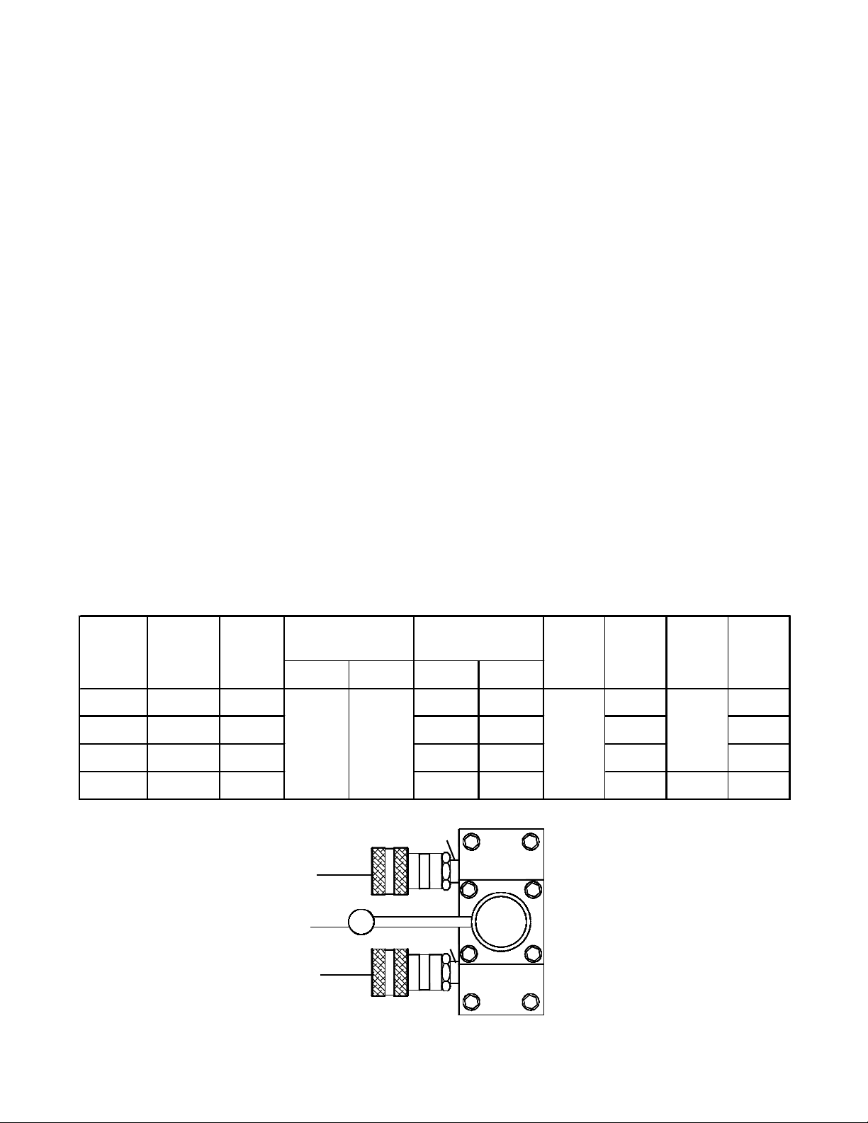
3/8"-18 NPTF
Coupler
(not included)
Control Valve Handle
3/8"-18 NPTF
Coupler
(not included)
Output Flow Rate
(in3/min)
Valve
Type
4-way, 3
position
Motor
(HP)
Motor
Voltage
(V)
110/115
Current
(A)
Figure 1 - Typical Control Valve with Couplers
2

Electric Motor
Control Box
Electric Motor
Control Valve
Control Valve
Lever
Oil Output
Ports
Carry Handle
Drain Plug
Figure 2 - Typical PE series Electric Pump Components
(PE1002 shown)
Electric Motor
ON/OFF Switch
Vent Cap
Power Cord
Reservoir
Control Valve
Control Valve
Lever
Oil Output
Ports
Carry Handle
Drain Plug
Figure 3 - Typical PEW series Electric Pump Components
(PEW1002 shown)
Power Cord
Reservoir
SAFETY INFORMATION
Read all the INSTRUCTIONS and WARNINGS in the manual provided within. Failure to heed these warnings may
result in personal injury as well as property damage.
WARNING
!
• Do not exceed the rated capacity of this device.
• Never attempt to lift a load weighing more than the
capacity of the cylinder.
• Burst hazard exists if hose or connection pressure
exceeds rated pressure.
• Use gauge or other load measuring instrument to
monitor load.
• Use of incorrect power source will damage the motor.
• Do not use an ungrounded (two-prong) extension cord.
• Do not install, remove or rewire the motor with power
applied. Have qualified technician to install, adjust
and service the motor.
• Do not operate this device in an extreme temperature,
explosive atmosphere or in the presence of conductive
liquids.
• Always inspect hoses and connections for damage
prior to use.
• Always tie up long hair, wear protective clothing and
eye protection when operating this equipment.
• Keep hand and feet away from cylinder and workpiece
during operation.
• Ensure the device is placed on a hard, level surfaces.
• Always ensure that the chosen application is stable
to work on and around.
• Do not subject the pump and its components to shock
loads.
• Do not subject the hose to potential hazard such as
sharp objects, extreme heat or heavy impact.
• Do not connect to application which can return more
oil to the reservoir than the pump reservoir can hold.
• Do not handle pressurized hose. Escaping oil under
high pressure can penetrate the skin, causing
serious injury.
• The load must be centered on the ram, or equally
distributed on multiple rams.
• Never hold or stand directly in line with any hydraulic
connections while pressurizing.
• Do not work under a lifted load. This device is not
suitable for use as support device!
• Release all line pressure before disconnecting hoses.
• When loading a cylinder, always insure that coupler,
port, and adapter threads have not been damaged.
• Failure to heed these warnings may result in personal
injury as well as property damage.
• If oil leakage is detected, discontinue use of the pump
immediately and contact your nearest BVA Hydraulics Authorized Service Center.
WARNING
!
WARNING!
To avoid crushing and
related injuries:
Do not work on, under or
around a lifted load.
Vent Cap
Remote
Pendant
3

BEFORE USE
Read all instructions carefully before attempting to
assemble or operate these pumps. Most malfunctions
in new equipment are the result of improper operation
and/or improper set-up assembly.
Visually inspect all components for shipping damage.
Do not use if any damage is found.
Note: E-Pumps are shipped without hydraulic oil filled.
Add oil before starting motor and operation.
Familiarize yourself with the specification and illustrations
in this owner manual. Use service parts drawing on page
8 thru 11 as reference of location and assembly.
Electrical Connections:
1. Compare motor nameplate against power availability
to prevent motor burnout or dangerous electrical
overloading.
2. (a) Model PE0501/PEW0501 (0.5hp), PE1002/
PEW1002 (1hp) and PE1503/PEW1503 (1.5hp)
motors are wired for 110 volts unless otherwise
specified, and are supplied with a plug and cord.
(b) Model PE3005 & PEW3005 (3hp) have accessible
motor leads and should be connected only by a
qualified electrician to prevent improper connection and
possible damage to the motor.
3.Try to minimize the use of long extension cord and
make sure the wire size is adequate and with grounded
connections.
Hydraulic Connections:
1. Make sure to use correct type of hydraulic oil specified
by the manufacturer. Check and make sure the oil
level in reservoir is at about 2" from top of reservoir
plate, with cylinders retracted and motor off.
2. Use of pressure gauge is strongly recommended.
Attach a pressure gauge between the pump and
cylinder to monitor pressure on cylinder.
3. Make sure coupler, hose, valve, gauge are tighten
securely to prevent accidental removal of components
while in use. Hoses shall not be kinked or twisted.
OPERATION
1. Check oil level, add oil if necessary.
2. Make sure system fittings and connections are tight
and leak free.
3. Place control valve lever in the middle (Neutral/Hold)
position to prevent accidental lifting or moving of load.
4. To
start the motor:
(a) For PE series, turn the ON/OFF switch on the
control box to ON position.
(b) For PEW series, press and hold on the switch of
the remote pendant.
5. Let the pump idle for a few minutes before put into
operation.
Note. To ensure smooth operation, bleed air from the
system by fully advancing and retracting the cylinder
several times.
6. Use the control valve lever to control the direction of
fluid flow. These pumps are equipped with a 4-way 3position valve. Refer to figure 3(a) on page 5 for the
flow path.
7. Always monitor the pressure, load and position.
8. Shift the control valve, until desired pressure, load or
position is read.
Note: Do not continue to operate pump after cylinder
plunger is fully extended or retracted.
9. To turn off the motor:
(a) For PE series, turn the ON/OFF switch on the
switch box to OFF position.
(b) For PEW series, the motor will stop when the
switch is released.
10.Depressurize all connections before disconnect.
Note: Control valves on these pumps are 4-way, 3position, for use with double acting cylinders. If your
application require a 3-way setting shown in figure 3(b),
it can be changed by an authorized BVA Service Center.
If you have any doubt, please consult BVA Technical
Service 888-332-6419.
Note: Always secure threaded port connections with
non-hardening pipe thread compound. Take care not to
introduce compound into port orifices.
4. Do not exceed the rated capacity of the equipment
connected to the pump. Use larger capacity of
cylinders if necessary.
IMPORTANT: The pump's maximum working pressure
is 10,000 PSI. Make sure that all hydraulic equipment
such as cylinders, hoses, coupler and etc. used with
this pump are rated at 10,000 PSI operating pressure.
4
 Loading...