

PA600-M0_022012
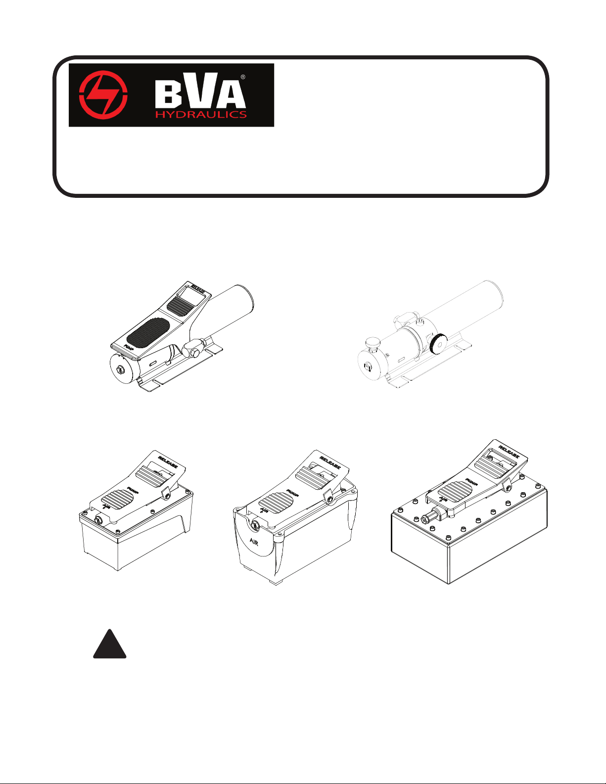
Air Hydraulic Pumps
Instruction Manual
MODELS: PA600, PA600H, PA1500, PA1500A, PA1500B, PA2000 & PA3801
SFA Companies 10939 N. Pomona Ave. Kansas City, MO 64153
Tel: 888-332-6419 * Fax: 816-891-6599
E-mail: sales@bvahydraulics.com Website: www.bvahydraulics.com
Maximum Operating Pressure 10,000 PSI
PA600
PA1500, PA1500A
& PA1500B
This is the safety alert symbol. It is used to alert you to potential personal injury hazards.
Obey all safety messages that follow this symbol to avoid possible injury or death.
!
PA2000
PA600H
PA3801
Printed in Taiwan

SAFETY AND GENERAL INFORMATION
Save these instructions. For your safety, read and understand
the information contained within. The owner and operator shall
have an understanding of this product and safe operating
procedures before attempting to use this product. Instructions
and safety information shall be conveyed in the operator's
native language before use of this product is authorized. Make
certain that the operator thoroughly understands the inherent
dangers associated with the use and misuse of the product. If
any doubt exists as to the safe and proper use of this product
as outlined in this factory authorized manual, remove from
service immediately.
Inspect before each use. It is recommended that, prior to each
use, an inspection be done by qualied personnel and that any
missing or damaged parts, decals, warning/ safety labels or
signs be replaced with BVA Hydraulics authorized replacement
parts only. Any pump that appears to be damaged in any way,
is worn, leaking or operates abnormally shall be removed from
service immediately until such time as repairs can be made.
Any pump that has been or suspected to have been subject
to a shock load (a load dropped suddenly, causing the system
pressure to exceed 10,000 PSI), shall be removed from service
immediately until checked out by a BVA Hydraulics authorized
service center. Owners and operators of this equipment shall
be aware that the use and subsequent repair of this equipment
may require special training and knowledge.
PRODUCT DESCRIPTION
BVA Hydraulics Air Hydraulic Pumps are engineered to meet
most Industrial Standards for Performance and Safety. Its
unique hydraulic circuit allows quick displacement of hydraulic
uid under no load conditions and easy pumping in loaded
conditions. These air actuated pumps supply compressed
hydraulic uid to compatible applications i.e. rams, presses,
spreaders, compactors and crimping machines, anywhere
that 10,000 PSI of uid pressure is needed. Special skill,
knowledge and training may be required for a specic task
and the product may not be suitable for all the jobs described
above. Unsuitable applications would include applications that
call for a device to move, level or support persons, animals,
hazardous materials, mobile homes/ dwellings in general,
mirrors and/or plate glass, and/or to connect/secure hatches,
components, etc. between bulkheads. The user must ultimately
make the decision regarding suitability of the product for any
given task and assume the responsibility of safety for himself
or herself and others in the work area.
WARNING:
!
or
property damage, ensure that the rated working
pressure of each pressurized attachment be equal to
or greater than the rated working pressure developed
by the hydraulic pump.
WARNING: Always check connections before using.
!
Alteration of these products is strictly prohibited. Use
only those adapters and attachments provided and
approved by the manufacturer.
To reduce the risk of personal injury and/
Foot Pedal
Plastic Cap/
Air Input Port
Reservoir Cap
(not shown)
Hand Button
Reservoir
Manifold Plug/
Oil Output Port
Base Plate
Figure 1 - Model PA600 Components Figure 2 - Model PA600H Components
Manifold Plug/ Oil Output Port
Shipping/ Air Vent Plug
(replace Shipping Plug with
Air Vent Plug prior to use)
Plastic Cap/
Air Input Port
Manifold Plug/
Oil Output Port
(Advance)
Foot Pedal
Plastic Cap/ Air Input Port
Reservoir Cap
(not shown)
Release
Valve Knob
Base Plate
Reservoir
Reservoir
Figure 3 - Models PA1500, PA1500B, PA2000 & PA3801 Components (PA1500 shown)
2

! WARNING
• St u d y, un d e r s ta n d , and follow all
instructions provided with and on this
device before use.
• No alterat ion shall be made to thi s
device.
• Al w ays wear protecti v e gear whe n
operating hydraulic equipment.
• Keep hydraulic equipment away from
ames and heat. Hydraulic uid can ignite
and burn. Do not operate if leaks are
detected.
• Crush Hazard. Keep hands and feet away
from loading area. Avoid pinch points
or crush points that can be created by
the load, cylinder, or any equipment of
system.
• To avoid crushing and related injuries:
NEVER work on, under or around a
lifted load before it is properly supported
by appropriate means. Never rely on
hydraulic press ure alone to support
load.
HYDRAULIC PUMPS
• The user must be a qualied operator familiar with the
correct operation, maintenance, and use of pumps. Lack
of knowledge in any of these areas can lead to personal
injury.
• Do not exceed rated capacity of the pump or any equipment
in the system.
• Never attempt to lift a load weighing more than the capacity
of the cylinder.
• Burst hazard exists if hose or connection pressure exceeds
rated pressure.
• Inspect pump, cylinder, hoses and connections before
each use to prevent unsafe conditions from developing.
Do not use if damaged, altered or in poor condition. Do not
operate system with bent or damaged coupler or damaged
threads.
• Never hold or stand directly in line with any hydraulic
connections while pressurizing.
• Use gauge or other load measuring instrument to verify
load.
• Never attempt to disconnect hydraulic connections under
pressure. Release all line pressure before disconnecting
hoses.
• Do not subject the pump and its components to shock
loads.
• Use only approved accessories and approved hydraulic
uid.
• Never attach ANY component not authorized by
manufacturer.
• Always ensure that the chosen application is stable to work
on and around.
• Do not connect to application which can return more oil to
the reservoir than the pump reservoir can hold.
• Do not connect pump to hydraulic system powered by
another pump.
• This device is not suitable for use as support device! As
the system load is lifted, use blocking and cribbing to
guard against a falling load.
• Clear all personnel before lowering load or depressurizing
the system.
• Do not disassemble hydraulic cylinder, refer repairs to
qualied, authorized personnel.
HYDRAULIC HOSES & FLUID TRANSMISSION LINES
• Avoid short runs of straight line tubing. Straight line runs
do not provide for expansion and contraction due to
pressure and/or temperature changes.
• Reduce stress in tube lines. Long tubing runs should
be supported by brackets or clips. Before operating
the pump, tighten all hose connections with proper
tools. Do not overtighten. Connections should only be
tightened securely and leak-free. Overtightening can
cause premature thread failure or high pressure ttings
to burst.
• Should a hydraulic hose ever rupture, burst or need to be
disconnected, immediately shut off the pump and release
all pressure. Never attempt to grasp a leaking pressurized
hose with your hands. The force of escaping hydraulic
uid can inict injury.
• Do not subject the hose to potential hazard such as re,
sharp objects, extreme heat or cold, or heavy impact.
• Do not allow the hose to kink, twist, curl, crush, cut or bend
so tightly that the uid ow within the hose is blocked or
reduced. Periodically inspect the hose for wear.
• Do not pull, position or move setup by the hose.
• Hose material and coupler seals must be compatible with
hydraulic uid used. Hoses also must not come in contact
with corrosive materials such as battery acid, creosoteimpregnated objects and wet paint. Never paint a coupler
or hose.
• FAILURE TO HEED THESE WARNINGS MAY RESULT
IN PERSONAL INJURY AS WELL AS PROPERTY
DAMAGE.
3

Model
Number
Usable Oil
Capacity
(in3)
Rated
Pressure
(psi)
SPECIFICATIONS
Output Flow Rate
No Load Load
(in
3
/min)
Input Air
Pressure
(psi)
Output Port
Thread
(Oil)
Input Port
Threads
(Air)
Weight
(lbs w/
uid)
PA600
PA600H 12.7
PA1500,
PA1500B
PA1500A 91.5 61 11 18.7
PA2000 122 65 12 20.1
PA3801 231.9 65 12 26.4
BEFORE USE AND SET UP
1. Familiarize yourself with the specications and illustrations
in this owners manual. Know your pump, its limitations
and how it operates before attempting to use. Refer to
specication chart on page 3 for details of oil port thread
size, usable oil capacity, and more. If in doubt, contact BVA
Hydraulics Technical Service (888) 332-6419.
2. For models PA1500, PA1500A, PA1500B, PA2000 &
PA3801: Replace shipping plug (red color) with air vent
plug (black color) before use.
3. Air Connection: Remove plastic cap, connect suitable air
supply to air input port. Air input port is designed to t the
popular 1/4" NPT air nipple (not included). Ensure
your air source can dedicate 7.8CFM @ 110~175 PSI to
each pump operated.
4. Hydraulic Connection: Clean all areas around the oil port
of pump and cylinder. Inspect all threads and tting for
signs of wear or damage and replace as needed. Clean all
hose ends, couplers and union ends. Remove the manifold
plug, then connect oil output port to suitable ttings and
application/cylinder.
NOTICE: Always secure threaded port connections with high
grade, non-hardening pipe thread sealant. Teon tape can
be used if only one layer of tape is used and it is applied
carefully, two threads back, to prevent the tape from being
introduced into hydraulic system, which could cause jamming
of precision-t parts.
36.6
91.5 66 11 18.1
10,000
61 9
that
110 - 175 3/8” -18NPTF 1/4” - 18NPT
Correct application position can only be determined by
the operator of the equipment.
For Model PA600H: (Hand Button Pump)
1. To extend the cylinder:
a. Close release valve by turning it clockwise rmly.
b. Depress the hand button on top of the air input port
until desired pressure, load or position is reached.
2. To hold the cylinder in position, simply release the hand
button to deactivate the pump.
3. To retract cylinder, open release valve by turning it counterclockwise slowly.
For Models PA600, PA1500, PA1500B, PA2000 & PA3801:
1. To extend the cylinder, depress on the foot pedal marked
"Pump" (horizontal portion) until desired pressure, load or
position is reached.
2. To hold the cylinder in position, release the foot pedal to
deactivate the pump.
3. To retract the cylinder, depress the release valve by stepping
on the foot pedal marked "Release" (raised, stirrup shaped
portion).
For Model PA1500A:
1. Install in-line pressure gauge between air pump and
cylinder.
2. Loosen External Pressure Relief Adjustment Screw fully.
3. Begin pumping air while monitoring pressure gauge. Tighten
Adjustment Screw (approximately 1/4 turn increments) until
gauge reaches desired working pressure.
14.1
WARNING:
!
or
property damage, Hydraulic connections must be
securely fastened before building pressure in the system.
Release all system pressure before loosening any
hydraulic connection in the system.
To reduce the risk of personal injury and/
OPERATION
WARNING: Always monitor pressure, load or position
!
using suitable equipment. Pressure may be monitored by
means of an optional manifold and gauge. Load may be
monitored by means of a load cell and digital indicator.
External Pressure Relief
Adjustment Screw
NOTICE: Never operate a pump which is disconnected
from application. If operate in this condition, the hose and
connections will become pressurized. This increases burst
hazard. Damage may occur to pump and its components.
4

MAINTENANCE
3. Wipe up any spilled uid and reinstall the air vent plug/
reservoir cap.
NOTICE: Use only good quality hydraulic uid. Never use
brake uid, transmission uid, turbine oil, motor oil, alcohol,
glycerin etc. Use of other than good quality hydraulic oil will
void warranty and damage the pump, hose, and application.
We recommend Mobil DTE 13M or equivalent
Changing Hydraulic Fluid
1. For best results, change uid once a year or every 300
hours of use.
2. Repeat # 2 above, then pour used uid into a sealable
container.
1. Inspect hoses and connections daily. Replace damaged
components immediately.
2. Tighten connections as needed. Use non-hardening pipe
thread compound when servicing connections.
3. Dispose of uid in accordance with local regulations.
4. Fill with a good quality hydraulic uid as recommended
above. Reinstall air vent plug/ reservoir cap. Lubrication
When pump is operated on daily basis, the manufacturer
recommends installing an inline oiler and air dryer. Use SAE
Adding Hydraulic Fluid
grade oil (5W to 30W).
1. Depr essu rize and discon nect hydra ulic hose from
application/ cylinder.
a.For Model PA600 & PA600H: With pump in its vertical
posit ion, rem ove the rese rvoir cap located on the
reservoir.
b.For Model PA1500, AP1500B, PA2000 & PA3801: With
pump in its upright, horizontal position, remove the air vent
plug located on the top plate of the reservoir.
2. Use a small funnel to ll the oil to within 3/4" (19mm) of
Storage
1. When not in use, depressurize and disconnect hydraulic
pump from application.
2. Wipe clean, thoroughly and store in clean, dry environment.
Avoid temperature extremes.
3. For transportation or long storage, replace the air vent plug
with shipping plug (for model PA1500, PA1500B, PA2000
& PA3801).
the opening.
TROUBLESHOOTING GUIDE
The following information is intended as an aid in determining if problem exists. Pumps should be repaired only by authorized
BVA Service Center. For repair service, contact service center in your area.
Symptom Possible Causes Corrective Action
Application does not extend, move or
respond to pressurized uid
Application responds to pressurized uid,
but system does not maintain pressure
Application responds slower than normal
Application does not return uid to pump
(i.e. cylinder will not retract)
Application does not fully extend (cylinder
or spreader)
• Overload condition
• Loose couplers
• Faulty couplers
• Pump malfunction
• Inadequate air supply
• Overload condition
• Pump or valve malfunction
• Application/connection leaking
• Loose connection or coupler
• Restricted hydraulic line or tting
• Application/connection leaking
• Malfunctioning coupler, damaged
application
• Reservoir overlled
• Fluid level in pump is low
• Remedy overload condition
• Tighten couplers
• Replace couplers
• Contact service center
• Ensure air source can dedicate
7.8 CFM @ 110~175 PSI
• Remedy overload condition
• Contact Service Center
• Replace application/connection
• Tighten connection or coupler
• Clean and replace if damaged
• Replace application/connection
• Secure load by other means. Depressurize
pump and hose, remove coupler and/or
application, then renew or replace
• Secure load by other means. Depressurize
pump and hose, remove application, then
drain uid to proper level
• Secure load by other means. Depressurize
pump and hose, remove application, then ll
uid to proper level
Poor performance • Fluid level in pump is low • Ensure proper uid level
5
 Loading...