


PA1500L-M0 rev 08/07
Air Hydraulic Pumps
Instruction Manual
MODELS: PA1500L & PA3801L
SFA Companies 10939 N. Pomona Ave. Kansas City, MO 64153
Tel: 888-332-6419 * Fax: 816-891-6599
E-mail: sales@bvahydraulics.com Website: www.bvahydraulics.com
This is the safety alert symbol. It is used to alert you to potential personal injury hazards.
!
Obey all safety messages that follow this symbol to avoid possible injury or death.
Maximum Operating Pressure 10,000 PSI
Printed in Taiwan
Save these instructions. For your safety, read and
understand the information contained within. The owner and
operator shall have an understanding of this product and safe
operating procedures before attempting to use this product.
Instructions and safety information shall be conveyed in
the operator's native language before use of this product
is authorized. Make certain that the operator thoroughly
understands the inherent dangers associated with the use and
misuse of the product. If any doubt exists as to the safe and
proper use of this product as outlined in this factory authorized
manual, remove from service immediately.
Inspect before each use. It is recommended that, prior to
each use, an inspection be done by qualified personnel and
that any missing or damaged parts, decals, warning/ safety
labels or signs be replaced with BVA Hydraulics authorized
replacement parts only. Any pump that appears to be damaged
in any way, is worn, leaking or operates abnormally shall be
removed from service immediately until such time as repairs
can be made. Any pump that has been or suspected to have
been subject to a shock load (a load dropped suddenly,
causing the system pressure to exceed 10,000 PSI), shall
be removed from service immediately until checked out by
a BVA Hydraulics authorized service center. Owners and
operators of this equipment shall be aware that the use and
subsequent repair of this equipment may require special
training and knowledge.
PRODUCT DESCRIPTION
BVA Hydraulics Air Hydraulic Pumps are engineered to meet
most Industrial Standards for Performance and Safety. Its
unique hydraulic circuit allows quick displacement of hydraulic
fluid under no load conditions and easy pumping in loaded
conditions. These air actuated pumps supply compressed
hydraulic fluid to compatible applications i.e. rams, presses,
spreaders, compactors and crimping machines, anywhere
that 10,000 PSI of fluid pressure is needed. Special skill,
knowledge and training may be required for a specific task
and the product may not be suitable for all the jobs described
above. Unsuitable applications would include applications
that call for a device to move, level or support persons,
animals, hazardous materials, mobile homes/ dwellings in
general, mirrors and/or plate glass, and/or to connect/secure
hatches, components, etc. between bulkheads. The user
must ultimately make the decision regarding suitability of the
product for any given task and assume the responsibility of
safety for himself or herself and others in the work area.
!
WARNING:
property damage, ensure that the rated working pressure of
each pressurized attachment be equal to or greater than the
rated working pressure developed by the hydraulic pump.
!
Always check connections before using. Alteration
of these products is strictly prohibited. Use only those
adapters and attachments provided and approved by the
manufacturer.
To reduce the risk of personal injury and/or
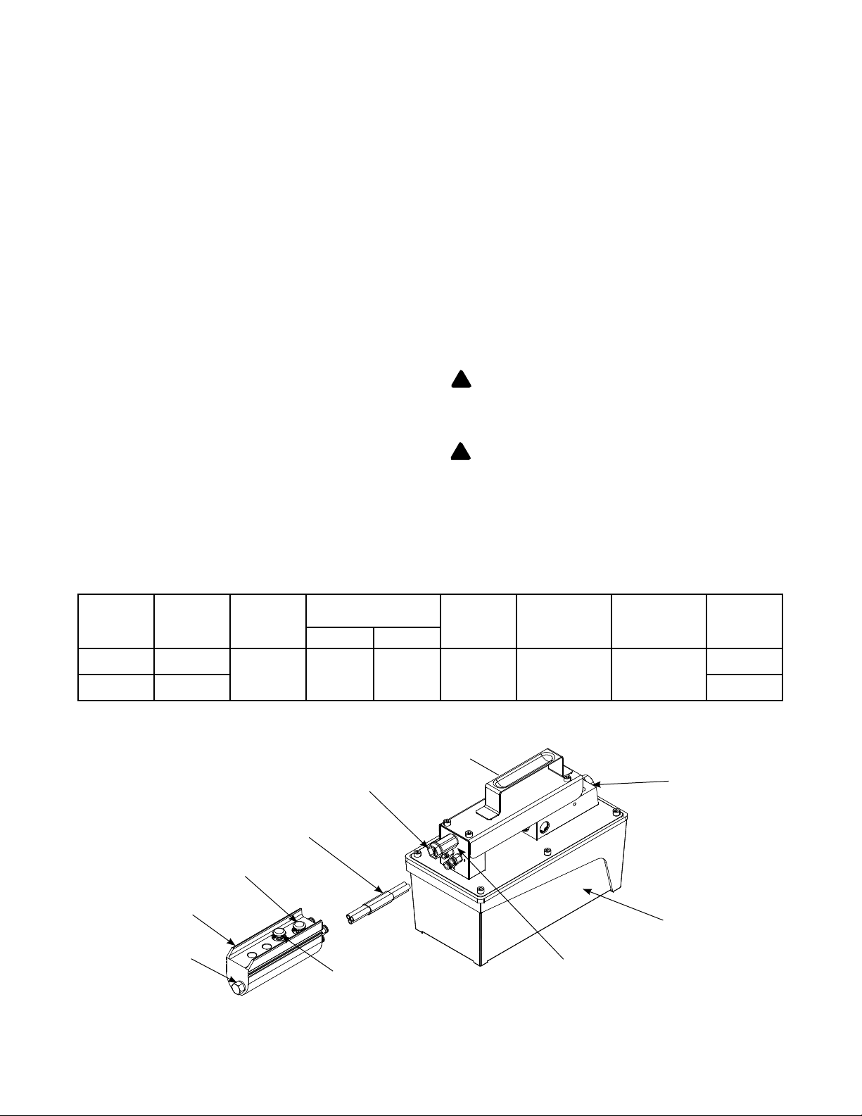
SPECIFICATIONS
Model
Number
PA1500L 91.5
PA3801L 231.9 30.4
Remote Control
Second Air Input Port
Usable Oil
Advance Button
Hex Plug/
Capacity
(in3)
Color Coded Hose
Rated
Pressure
(psi)
10,000 61 10 110-175 3/8"-18NPT 1/4"-18NPT
Output Flow Rate
(in3/min)
No Load Load
Plastic Plug
Retract Button
Inpur Air
Pressure
(psi)
Handle
Output
Port
Threads
First Air
Input Port
Input
Port
Threads
Oil Reservoir
Weight
(lbs)
19.4
Manifold Plug/
Oil Output Port
Figure 1 - Model PA1500L & PA3801L Components (PA1500L shown)
2
BEFORE USE
1. Before using this product, read the instruction manual
completely and familiarize yourself thoroughly with the
product and the hazards associated with its improper
use.
2. Know your pump, its limitations and how it operates before
attempting to use
3. Use Spare Parts List Illustration on pages 6 & 8 as reference
of location and assembly.
4. Replace shipping plug (red color) with air vent plug (black
color). Refer to #58 on parts illustration.
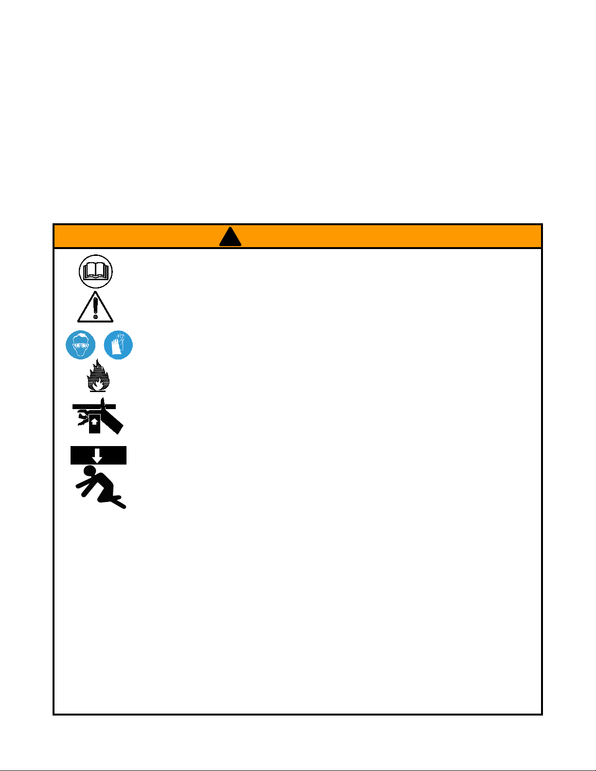
! WARNING
• Study, understand, and follow all
instructions provided with and on this
device before use.
• All WARNING statements must be
carefully observed to help prevent
personal injury.
• No alteration shall be made to this
device.
• Always wear protective gear when
operating hydraulic equipment.
• Keep hydraulic equipment away from
flames and heat. Hydraulic fluid can
ignite and burn. Do not operate if
leaks are detected.
•
Crush Hazard. Keep hands and feet
away from loading area. Avoid pinch
points or crush points that can be
created by the load, cylinder, or any
equipment of system.
•
To avoid crushing and related injuries:
NEVER work on, under or around
a lifted load before it is properly
supported by appropriate mechanical
means. Never rely on hyd raulic
pressure alone to support load.
HYDRAULIC PUMPS
•
The user must be a qualified operator familiar with the
correct operation, maintenance, and use of pumps. Lack of
knowledge in any of these areas can lead to personal injury.
• Do not exceed rated capacity of the pump or any equipment
in the system.
• Never attempt to lift a load weighing more than the capacity
of the cylinder.
• Burst hazard exists if hose or connection pressure exceeds
rated pressure.
• Do not subject the pump and its components to shock
loads.
•
Inspect pump, cylinder, hoses and connections before each
use to prevent unsafe conditions from developing. Do not
use if they are damaged, altered or in poor condition. Do
not operate the system with bent or damaged coupler or
damaged threads.
• Never hold or stand directly in line with any hydraulic
connections while pressurizing.
•
Use gauge or other load measuring instrument to verify load.
ASSEMBLY
To hook up pump with remote control:
1. Connect red hose into air line coupler number 1 on the pump
and then put other end of red hose into corresponding slot
on remote control
2. Connect purple hose into air line coupler number 2 on
the pump and then put other end of purple hose into
corresponding slot on remote control.
3. Connect white hose to air line coupler number 3 on the
pump and then put other end of the white hose into
corresponding slot on remote control.
Note: Always secure threaded port connections with nonhardening pipe thread compound. Tighten securely to prevent
accidental removal of components while in use. Take care not
to introduce compound into port orifices.
• Never attempt to disconnect hydraulic connections under
pressure. Release all line pressure before disconnecting
hoses.
•
Use only approved accessories and approved hydraulic fluid.
•
Never attach ANY component not authorized by manufacturer.
• Always ensure that the chosen application is stable to work
on and around.
• Do not connect to application which can return more oil to
the reservoir than the pump reservoir can hold.
• Do not connect pump to hydraulic system powered by
another pump.
• This device is not suitable for use as support device! As
the system load is lifted, use blocking and cribbing to guard
against a falling load.
• All personnel must be clear before lowering load or
depressurizing the system.
• Never try to disassemble a hydraulic cylinder, refer repairs
to qualified, authorized personnel.
HYDRAULIC HOSES & FLUID TRANSMISSION LINES
• Avoid short runs of straight line tubing. Straight line runs
do not provide for expansion and contraction due to
pressure and/or temperature changes.
• Reduce stress in tube lines. Long tubing runs should be
supported by brackets or clips. Before operating the pump,
tighten all hose connections with proper tools. Do not
overtighten. Connections should only be tightened securely
and leak-free. Overtightening can cause premature thread
failure or high pressure fittings to burst.
• Should a hydraulic hose ever rupture, burst or need to be
disconnected, immediately shut off the pump and release
all pressure. Never attempt to grasp a leaking pressurized
hose with your hands. The force of escaping hydraulic fluid
can inflict injury.
• Do not subject the hose to potential hazard such as fire,
sharp objects, extreme heat or cold, or heavy impact.
• Do not allow the hose to kink, twist, curl, crush, cut or bend
so tightly that the fluid flow within the hose is blocked or
reduced. Periodically inspect the hose for wear.
• Do not pull, position or move setup by the hose.
• Hose material and coupler seals must be compatible with
hydraulic fluid used. Hoses also must not come in contact
with corrosive materials such as battery acid, creosoteimpregnated objects and wet paint. Never paint a coupler
or hose.
•
FAILURE TO HEED THESE WARNINGS MAY RESULT IN
PERSONAL INJURY AS WELL AS PROPERTY DAMAGE.
3

OPERATION
!
To reduce the risk of personal injury and/or
damage, hydraulic connections must be securely fastened
before building pressure in the system. Release all system
pressure before loosening any hydraulic connection in the
system.
!
Always monitor pressure, load or position using
suitable equipment. Pressure may be monitored by means of
an optional manifold and gauge. Load may be monitored by
means of a load cell and digital indicator. Correct application
position can only be determined by the operator of the
equipment.
1. Air connection: Remove plug from first or second air input
port (refer to figure 1) and connect to adequate air supply.
Install hex plug on unused air input port to prevent air
leakage.
2. Hydraulic connection: Remove manifold plug from oil
output port and connect to suitable application using 3/8
NPT connection.
3. To operate pump, press and hold on the advance button of
the remote control until desired pressure, load or position
is reached. Always monitor pressure, load or position
using suitable equipment. Pressure may be monitored by
means of an optional manifold and gauge (contact BVA
Hydraulics). Load may be monitored by means of a load
cell and digital indicator. Correct application position can
only be determined by the operator of the equipment.
4. To retract application, simply press the retract button on
the remote control.
property
MAINTENANCE
Important: Use only a good quality hydraulic jack fluid. Never
use brake fluid, transmission fluid, turbine oil, motor oil, alcohol,
glycerin etc. Use of other than good quality hydraulic oil will
void warranty and damage the pump, hose, and application.
We recommend Mobil DTE 13M or equivalent.
1. Inspect hoses and connections daily. Replace damaged
components immediately with BVA Hydraulics replacement
parts only.
2. Tighten connections as needed. Use non-hardening pipe
thread compound when servicing connections.
3. Use only good quality hydraulic fluid. We recommend Mobil
DTE 13M or equivalent.
Adding Hydraulic Fluid
1. Dep res sur ize and disc onn ect hydr aul ic hose from
application.
2. With pump in upright, horizontal position, remove the air
vent plug located on the top plate of the reservoir.
3. Use a small funnel to fill reservoir to within 3/4" (19mm) of
the opening.
4. Wipe up any spilled fluid and reinstall the air vent plug.
Changing Hydraulic Fluid
1. For best results, change fluid once a year.
2. Repeat step 2 on Adding Hydraulic Fluid, then pour used
fluid into a sealable container.
3. Dispose of fluid in accordance with local regulations.
4. Fill with a good quality hydraulic jack oil as recommended
above. Reinstall air vent plug.
Note: Both air input ports use a 1/4 NPT air nipple (not
included). It is recommended to install an inline air filter and
dryer upstream from the pump to provide clean, lubricated air.
Contact BVA Hydraulics for necessary accessories.
Lubrication
When pump is operated on daily basis, the manufacturer
recommends installing an inline oiler and air dryer. Use SAE
grade oil (5W to 30W).
Storage
1. When not in use, depressurize and disconnect hydraulic
hoses from application.
2. Wipe clean, thoroughly.
3. Store in clean, dry environment. Avoid temperature
extremes.
4. For transportation or long storage, replace the air vent plug
with shipping plug.
5. Shield pump with a protective cover.
4
 Loading...