

BVA Hydraulics P350, P601S, P1000, P1000AD, P2001 User Manual
Hand Pumps
Instruction Manual
MODELS: P350, P601S, P1000, P1000AD & P2001
SFA Companies 10939 N. Pomona Ave. Kansas City, MO 64153
Tel: 888-332-6419 * Fax: 816-891-6599
E-mail: sales@bvahydraulics.com Website: www.bvahydraulics.com
This is the safety alert symbol. It is used to alert you to potential personal injury hazards.
Obey all safety messages that follow this symbol to avoid possible injury or death.
!
Maximum Operating Pressure 10,000 PSI
P350-M1 102013
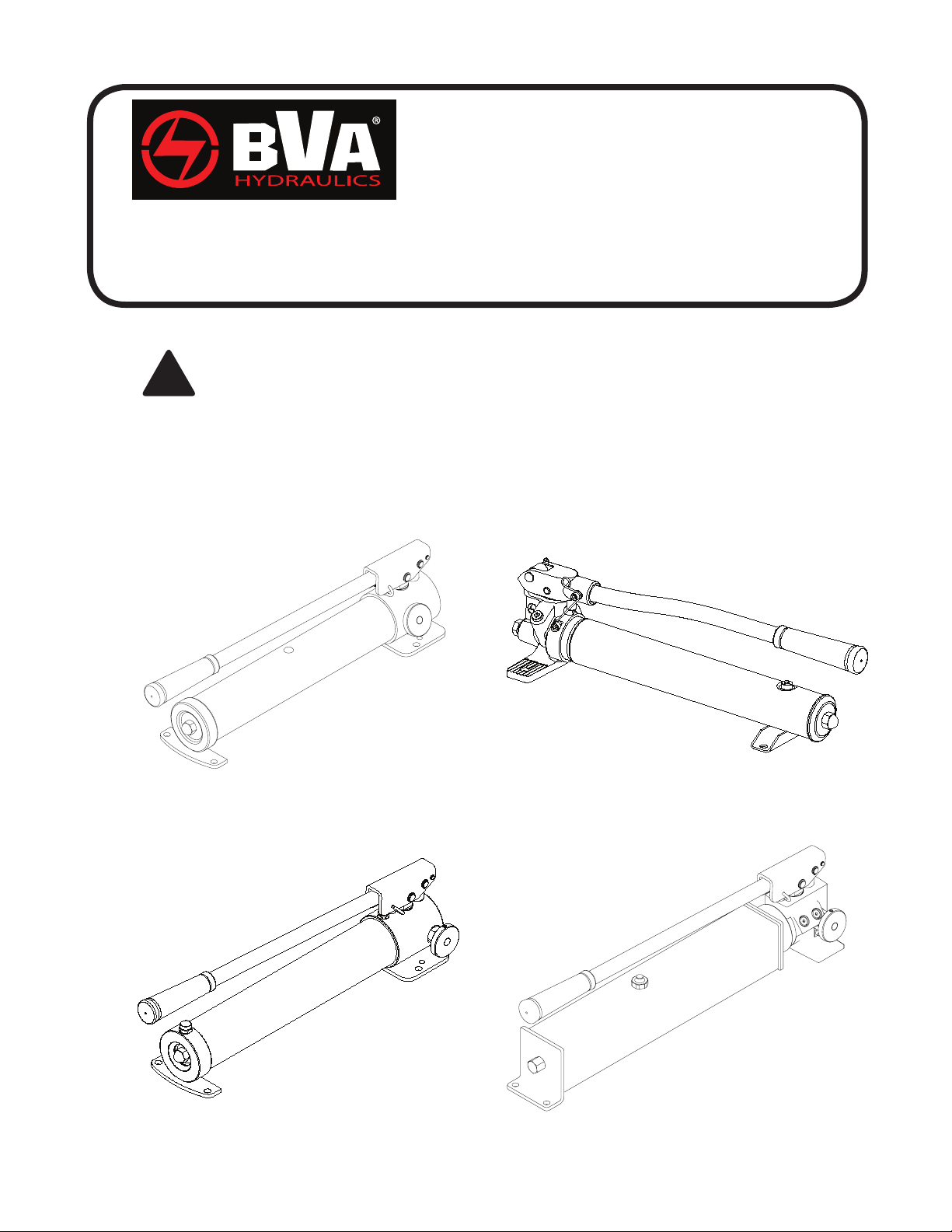
Models P350 & P1000
Model P1000AD
Model P601S
Model P2001
Printed in Taiwan
SAFETY AND GENERAL INFORMATION
Save these instructions. For your safety, read and understand the information contained within. The owner and operator shall
have an understanding of this product and safe operating procedures before attempting to use this product. Instructions and
safety information shall be conveyed in operator’s native language before use of this product is authorized. Make certain that the
operator thoroughly understands the inherent dangers associated with the use and misuse of the product. If any doubt exists as
to the safe and proper use of this product as outlined in this factory authorized manual, remove from service immediately.
Inspect before each use. It is recommended that, prior to each use, an inspection be done by qualied personnel and that any
missing or damaged parts, decals, warning/safety labels or signs be replaced with factory authorized replacement parts only. Any
pump that appears to be damaged in any way, is worn, leaking or operates abnormally shall be removed from service immediately
until such time as repairs can be made. Owners and operators of this equipment shall be aware that the use and subsequent
repair of this equipment may require special training and knowledge.
PRODUCT DESCRIPTION
BVA Hydraulic Hand Pumps are engineered to meet most industrial standards for Performance and Safety. Hand Pump model
number P350, P1000, P1000AD and P2001 have a unique 2 stage hydraulic circuit, which allows quick displacement of hydraulic
uid under no load conditions and easy pumping in loaded conditions. These lever operated pumps supply compressed hydraulic
uid to compatible applications i.e. rams, presses, spreaders, compactors and crimping machines, anywhere that 10,000 PSI
of uid pressure is needed. Special skill, knowledge and training may be required for a specic task and the product may not
be suitable for all the jobs described above. Unsuitable applications would include applications that call for a device to move,
level or support persons, animals, hazardous materials, mobile homes/ dwellings in general, mirrors and/or plate glass, and/or to
connect/secure hatches, components, etc. between bulkheads. The user must ultimately make the decision regarding suitability
of the product for any given task and assume the responsibility of safety for himself and others in the work area.
WARNING: Always check connections before using. Alteration of these products is strictly prohibited. Use only those
!
adapters and attachments provided and approved by the manufacturer.
WARNING: To reduce the risk of personal injury and/or property damage, ensure that the rated working pressure of each
!
pressurized attachment be equal to or greater than the rated working pressure developed by the hydraulic pump.
WARNING: Model P601S is operated with a non-vented reservoir. If the reservoir is subjected to high pressure, the casing
!
may rupture. Never attempt to return more oil to the reservoir than it is capable of holding.
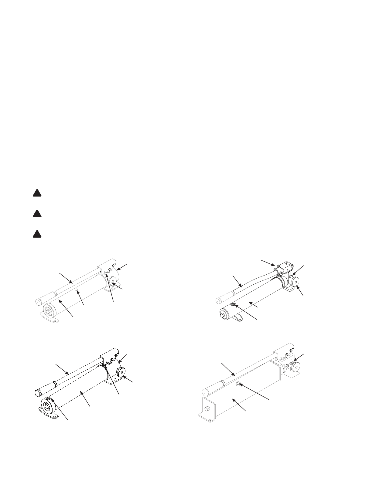
Oil Outlet Port
Handle
Reservoir
Oil Filler Plug/ Vent Plug
Figure 1 - Model P350 and P1000 Components
Handle
Spring Loaded
Handle Lock Pin
1/4”-18NPTF (P350)
3/8” -18NPTF (P1000)
Release Valve
Oil Outlet Port
3/8” -18NPTF
Release Valve
Handle Lock Latch
Handle
Reservoir
Oil Filler Screw
Figure 2 - Model P601S Components
Handle
Oil Outlet Port
3/8” -18NPTF
Release
Valve
Oil Outlet Port
3/8” -18NPTF
Spring Loaded
Handle Lock Pin
Reservoir
Reservoir
Oil Filler Plug/ Vent Plug
Figure 3 - Model P1000AD Components Figure 4 - Model P2001 Components
2
Vent Screw
SPECIFICATIONS
Usable
Model Pump Type
P350 Two-speed 21.3 200
P601S
P1000
P1000AD 61.0 200 0.81 0.14 99 0.82 3.94
P2001 122.0 200 0.81 0.14 95 0.82 2.56 24.2
Single-
speed
Two-speed
Oil
Capacity
(in3)
36.5 0.15 109 0.75 3.74 13.0
61.0 200 0.81 0.14 99 0.82 3.94 13.7
Pressure Rating
(psi)
1st
Stage
2nd
Stage
10,000
Oil Displacement
per Stroke (in3)
1st
Stage
0.18 0.05 88 0.38 2.56 6.6
2nd
Stage
Operating
Force
(lbs)
Piston
Stroke
(in)
Mounting
Plate
Holes Dis-
tance (in)
Weight
! WARNING
• Study, understand, and follow all
instructions provided with and on this
device before use.
• All WARNING statements must be
carefully observed to help prevent
personal injury.
• No alteration shall be made to this
device.
• Always wear protective gear when
operating hydraulic equipment.
• Keep hydraulic equipment away from
ames and heat. Hydraulic uid can
ignite and burn. Do not operate if
leaks are detected.
•
Crush Hazard. Keep hands and feet
away from loading area. Avoid pinch
points or crush points that can be
created by the load, cylinder, or any
equipment of system.
•
To avoid crushing and related injuries:
NEVER work on, under or around
a lifted load before it is properly
supported by appropriate mechanical
means. Never rely on hydraulic
pressure alone to support load.
HYDRAULIC PUMPS
•
The user must be a qualied operator familiar with the
correct operation, maintenance, and use of pumps. Lack of
knowledge in any of these areas can lead to personal injury.
• Do not exceed rated capacity of the pump or any equipment
in the system.
• Never attempt to lift a load weighing more than the capacity
of the cylinder.
• Burst hazard exists if hose or connection pressure exceeds
rated pressure.
•
Inspect pump, cylinder, hoses and connections before each
use to prevent unsafe conditions from developing. Do not
use if they are damaged, altered or in poor condition. Do
not operate the system with bent or damaged coupler or
damaged threads.
• Never hold or stand directly in line with any hydraulic
connections while pressurizing.
•
Use gauge or other load measuring instrument to verify load.
• Never attempt to disconnect hydraulic connections under
pressure. Release all line pressure before disconnecting
hoses.
• Do not subject the pump and its components to shock
loads.
•
Use only approved accessories and approved hydraulic uid.
•
Never attach ANY component not authorized by manufacturer.
• Always ensure that the chosen application is stable to work
on and around.
• Do not connect to application which can return more oil to
the reservoir than the pump reservoir can hold.
• Do not connect pump to hydraulic system powered by
another pump.
• This device is not suitable for use as support device! As
the system load is lifted, use blocking and cribbing to guard
against a falling load.
• All personnel must be clear before lowering load or
depressurizing the system.
• Never try to disassemble a hydraulic cylinder, refer repairs
to qualied, authorized personnel.
HYDRAULIC HOSES & FLUID TRANSMISSION LINES
• Avoid short runs of straight line tubing. Straight line runs
do not provide for expansion and contraction due to
pressure and/or temperature changes.
• Reduce stress in tube lines. Long tubing runs should be
supported by brackets or clips. Before operating the pump,
tighten all hose connections with proper tools. Do not
overtighten. Connections should only be tightened securely
and leak-free. Overtightening can cause premature thread
failure or high pressure ttings to burst.
• Should a hydraulic hose ever rupture, burst or need to be
disconnected, immediately shut off the pump and release
all pressure. Never attempt to grasp a leaking pressurized
hose with your hands. The force of escaping hydraulic uid
can inict injury.
• Do not subject the hose to potential hazard such as re,
sharp objects, extreme heat or cold, or heavy impact.
• Do not allow the hose to kink, twist, curl, crush, cut or bend
so tightly that the uid ow within the hose is blocked or
reduced. Periodically inspect the hose for wear.
• Do not pull, position or move setup by the hose.
• Hose material and coupler seals must be compatible with
hydraulic uid used. Hoses also must not come in contact
with corrosive materials such as battery acid, creosoteimpregnated objects and wet paint. Never paint a coupler
or hose.
•
FAILURE TO HEED THESE WARNINGS MAY RESULT IN
PERSONAL INJURY AS WELL AS PROPERTY DAMAGE.
(lbs)
3
BEFORE USE
1. Before using this product, read the instruction manual completely and familiarize
yourself thoroughly with the product, its components and recognize the hazards
associated with its use.
2. Verify that the product and the application are compatible. Inspect before each
use. Do not use if bent, broken, leaking or damaged components are noted.
3. Replace worn or damaged parts and assemblies with BVA Hydraulics Authorized
Replacement Parts only (See Replacement Parts Section). Lubricate as
instructed in Maintenance Section.
4. Ensure method of conrming load is accurate and working properly. Have gauge
or load cell accuracy veried by qualied personnel on a yearly basis.
5.
Pumps should be stored where protected from the elements, abrasive dust,
and damage. Pumps can be stored horizontally or vertically.
SETUP
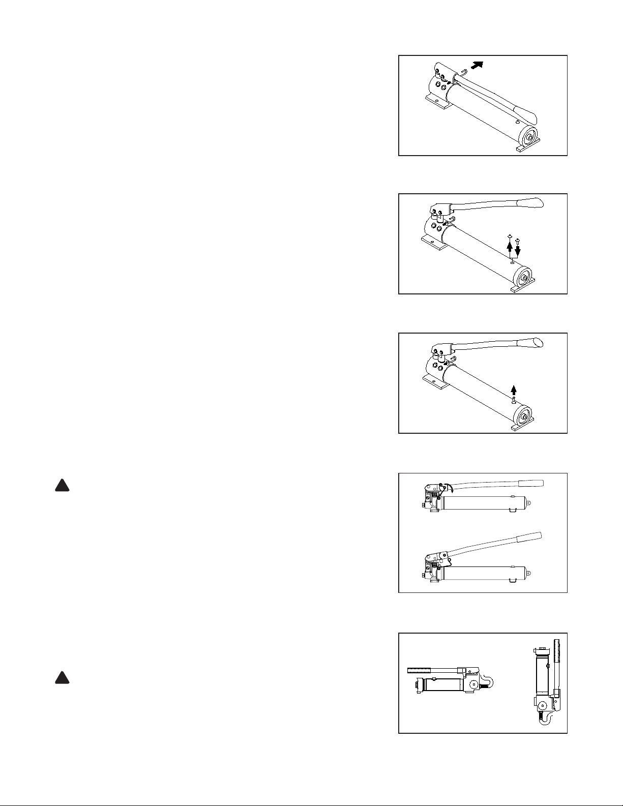
1. Prepare the pump for use:
A) For Models P350, P1000 & P1000AD:
• Pull spring loaded lock pin, pivot toward rear to unlock the handle (Fig. 5).
• Remove shipping plug and replace with air vent plug (Fig. 6).
• Pull vent plug stem upward before use, press down when moving or storing
the pump (Fig. 7).
B) For Model P601S:
• Push the handle lock latch to unlock the pump handle (Fig. 8).
C) For Model P2001:
• Pull spring loaded lock pin pivot toward rear to unlock the handle (Fig. 5).
2. Carefully remove the threaded plug from oil outlet port.
3. Connect coupler, tting or hose of matching threads. Install in-line pressure
gauge.
NOTICE: Use an approved, high-grade pipe sealant to seal all hydraulic
connections
4. Check for leaks in system and have repaired by qualied personnel as needed.
Before repairs are made, depressurize system by opening the release valve
counterclockwise, but no more than 2 full turns.
Figure 5 toward rear to unlock pump handle.
Figure 6 replace with air vent plug before initial use.
Figure 7 press down when moving or storing pump.
Pull spring loaded lock pin, pivot
Remove shipping plug and
Pull stem upward before use,
OPERATION
WARNING: ALWAYS monitor pressure, load or position using suitable
!
equipment. Pressure may be monitored by means of an optional manifold
and gauge. Load may be monitored by means of a load cell and digital
indicator. Correct application position can only be determined by the operator
of the equipment.
1. Connect the pump to suitable application.
2. Ensure the oil level is correct and the system ttings and connections are leak
free before operating the pump.
3. Pump may be used in horizontal and vertical position
as illustrated on Figure 9.
4. Close release valve by turning it clockwise. Finger tight ONLY. Using tools on
release valve can damage it and cause the pump to malfunction.
5. Pump handle until desired pressure, load or position is reached.
6. Pressure will maintain until the release valve is opened.
7. To retract application, turn the release valve knob slowly counterclockwise
(never more than 2 full turns).
WARNING: NEVER operate pump with release valve closed and
!
disconnected from application. If operated in this condition, the hose and
connections become pressurized. This increases burst hazard. Damage
may occur to pump and its components.
4
a)
b)
Figure 8 unlock the pump handle.
Figure 9 - Horizontal and Vertical Position
Push the handle lock latch to

MAINTENANCE
1. Inspect hoses and connections daily. Replace damaged
components immediately with BVA Hydraulics Replacement
Parts only.
2. Tighten connections as needed. Use pipe thread sealing
compound when servicing connections.
3. Use only good quality hydraulic uid. We recommend using
premium hydraulic uid. Never use brake uid, transmission
uid, turbine oil, motor oil, alcohol, glycerin etc. Use of
other than good quality hydraulic oil will void warranty and
damage the pump, hose, and application.
Changing Hydraulic Fluid
For best results, change uid once a year.
1. With pump in its upright, horizontal position, remove vented
oil ller plug/screw located on top of the reservoir, then pour
used uid into a sealable container.
2. Dispose of uid in accordance with local regulations.
3. Fill with a good quality hydraulic jack oil as recommended
above. Reinstall vented oil ller plug/screw.
Lubrication
Use a light machine oil to lubricate pivot points, hinges etc.
Adding Hydraulic Fluid
1. Depressurize and disconnect hydraulic hose from
application.
2. With pump in its upright, horizontal position, remove vented
oil ller plug/screw located on top of the reservoir.
3. Use a small funnel to ll reservoir to within 1/4” (6 mm) of
the opening.
4. Wipe up any spilled uid and reinstall the vented oil ller
plug/screw.
Storage
1. When not in use, depressurize and disconnect hoses from
application.
2. Wipe clean, throughly
3. Store in clean, dry environment. Avoid temperature
extremes. Lock handle into position using the spring loaded
locking pin mechanism.
4. Shield pump with a protective cover.
TROUBLESHOOTING GUIDE
The following information is intended as an aid in determining if problem exists. Pumps should be repaired only by authorized
BVA Service Center. For repair service, contact service center in your area.
Symptom Possible Causes Corrective Action
Erratic application action
Application does not extend,
move or respond to pressurized
uid
• Air in the system.
• External leak.
• Internal hydraulic leak.
• Overload condition.
• Release valve not closed.
• Loose couplers/connections.
• Faulty couplers/connections.
• Pump malfunction.
• Vent the system.
• Tighten all connections.
• Contact service center.
• Remedy overload condition.
• Ensure release valve closed.
• Tighten couplers/connections.
• Replace couplers/connections.
• Contact service center.
Application responds to
pressurized uid, but system does
not maintain
pressure
Application responds slower than
normal
Application does not return uid to
pump (i.e. cylinder will not retract)
Poor performance • Fluid level in pump is low. • Ensure proper uid level.
• Overload condition.
• Release valve not closed.
• Pump or valve malfunction.
• Application/connection leaking.
• Loose connection or coupler.
• Restricted hydraulic line or tting.
• Application/connection leaking.
• Malfunctioning coupler, damaged
application.
• Reservoir overlled
5
• Remedy overload condition.
• Ensure release valve closed.
• Contact Service Center.
• Replace application/connection.
• Tighten connection or coupler.
• Clean and replace if damaged.
• Replace application/connection.
• Secure load by other means. Open
release valve, depressurize pump and
hose, remove coupler and/or application,
then renew or replace.
• Secure load by other means. Open
release valve, depressurize pump and
hose, remove application, then drain
uid to proper level.
 Loading...