

J18122-M1 rev 07/08
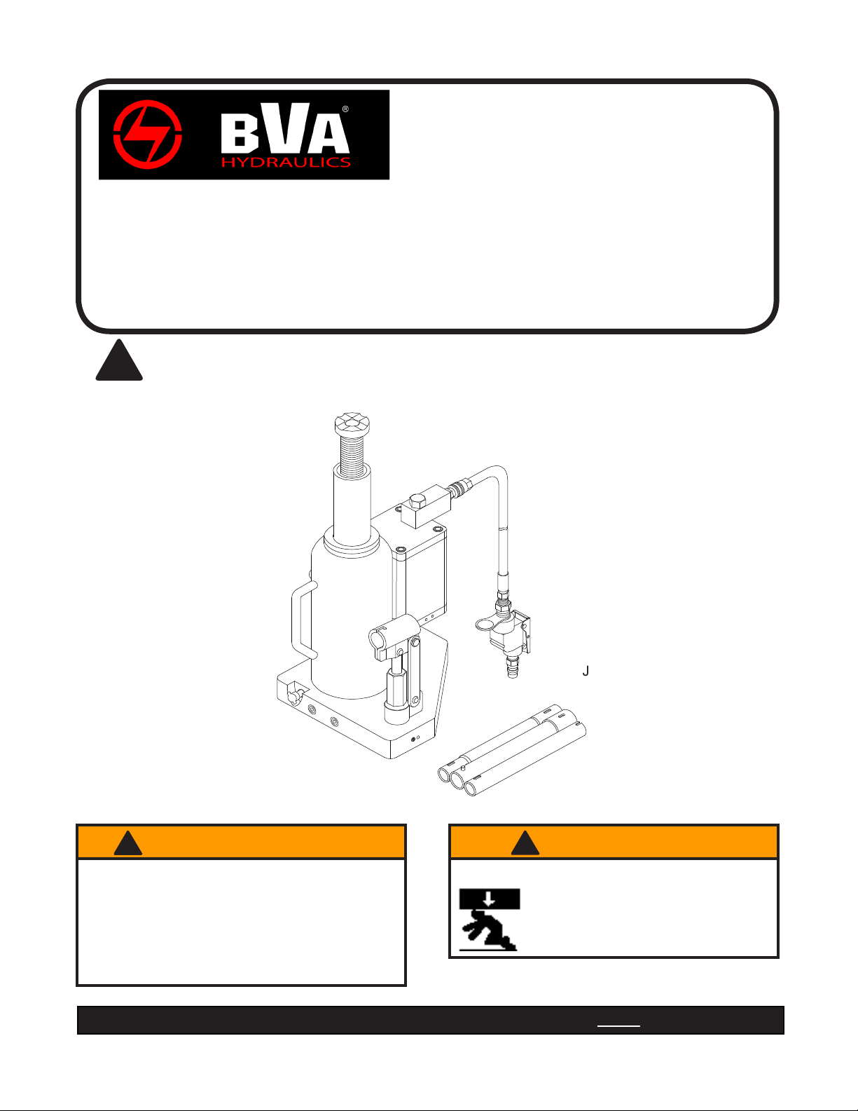
Air/Manual Hydraulic
Bottle Jack
Instruction Manual
MODELS: J18122 - 12 Ton Capactiy
J18202 - 20 Ton Capacity
J18302 - 30 Ton Capacity
SFA Companies 10939 N. Pomona Ave. Kansas City, MO 64153
Tel: 888-332-6419 * Fax: 816-891-6599
E-mail: sales@bvahydraulics.com Website: www.bvahydraulics.com
This is the safety alert symbol. It is used to alert you to potential personal injury hazards.
!
Obey all safety messages that follow this symbol to avoid possible injury or death.
J18122 shown
U.S. Patent No's. 5,341,723 • 5,946,912
! ADVERTENCIA
• Leer, comprender, y seguir las instrucciónes antes
de utilizar el aparato.
• El manual de instrucciónes y la información de
seguridad deben estar comunicado en lengua del
operador antes del uso.
• No seguir estas indicaciónes puede causar daños
personales o materiales.
Read this manual and follow all the Safety Rules and Operating Instructions before using this product.
! WARNING
To avoid crushing and related injuries:
NEVER work on, under or around a
load supported only by a hydraulic
jack. ALWAYS use adequately rated
jack stands.
SFA Companies
http://www.bvahydraulics.com
Printed in China

SAFETY and GENERAL INFORMATION
Save these instructions. For your safety, read, understand, and follow the information provided with and on this jack
before using. The owner and operator of this equipment shall have an understanding of this jack and safe operating
procedures before attempting to use. The owner and operator shall be aware that use and repair of this product
may require special skills and knowledge. Instructions and safety information shall be conveyed in the operator's
native language before use of this jack is authorized. If any doubt exists as to the safe and proper use of this jack,
remove from service immediately.
Inspect before each use. Do not use if broken, bent, cracked or damaged parts are noted. Any jack that appears
damaged in any way, or operates abnormally shall be removed from service immediately. If the jack has been or
suspected to have been subjected to a shock load (a load dropped suddenly, unexpectedly upon it), immediately
discontinue use until jack has been checked by a factory authorized service center (contact distributor or manufacturer
for list of authorized service centers). It is recommended that an annual inspection be done by qualied personnel.
Labels and Operator's Manuals are available from manufacturer.
PRODUCT DESCRIPTION
BVA Hydraulics Air Actuated Hydraulic Bottle Jacks are designed to lift, not support, rated capacity loads consisting
of one end of a vehicle. Immediately after lifting, the load must be supported by a pair of appropriately rated jack
stands. Ensure that air source can dedicate 7.8 CFM @ 110-175 psi to each jack operated. A minimum of 150 psi
air pressure is required to raise rated capacity load.
Never use hydraulic jack as a stand alone device. After lifting, immediately support the lifted load
!
with a pair of appropriately rated jack stands. Never place any portion of your body under the load while lifting or
lowering the load.
PREPARATION
Before Use
1.
Verify that the product and application are compatible, if in doubt call BVA Hydraulics Technical Service (888)
332-6419.
2. Before using this product, read the operator's manual completely and familiarize yourself thoroughly with the
product, its components and recognize the hazards associated with its use.
3. Assemble handle, ensure spring clips align with slots.
4. To familiarize yourself with basic operation, use the notched end of provided handle to engage and turn the release
valve:
a. Clockwise until rm resistance is felt to further turning. This is the ‘CLOSED’ release valve position used to
raise the ram plunger.
b. Counter-clockwise, but no more than 1 turn from the closed position. This is the ‘OPEN’ release valve
position used to lower the ram plunger.
5. With ram fully retracted, locate and remove the oil ller plug/screw. Insert the handle into the handle sleeve, then
pump 6 to 8 strokes. Ensure the oil level is just below the oil ller hole. Reinstall the oil ller plug/screw.
6. Pour a teaspoon of good quality, air tool lubricant into the air supply inlet of the lift control valve. Connect to air
supply and squeeze lift control valve for 3 seconds to evenly distribute lubricant.
7. This product is equipped with the popular 1/4" NPT air coupler. When installing a different air coupler of your
choice, ensure that thread tape or compound is used when servicing connections. To ensure dependable, trouble
free operation an inline air dryer and oiler is recommended.
8. Check that the pump operates smoothly and that the extension screw will thread up/down easily before putting
into service. Replace worn or damaged parts and assemblies with BVA Hydraulics authorized replacement parts
only.
Bleeding / Venting Trapped Air
With the release valve in the OPEN position (4b above) and with ram plunger fully lowered, locate and remove the
oil ller plug/screw. Insert the handle into the handle sleeve; then pump 6 to 8 full strokes. This will help release any
pressurized air which may be trapped within the reservoir. Oil level should be even with the bottom of the oil ller
hole. Reinstall the oil ller plug/screw.
2
! WARNING
• Study, understand, and follow all printed materials
provided with/on this product before use.
• Do not exceed rated capacity.
• This is a lifting device only!
• Immediately after lifting, support the load with
a pair of appropriately rated jack stands.
• Use only on hard, level surface.
• Do not use adapters or accessories that are not
provided initially.
• Lift only on areas of the vehicle as specied by the
vehicle manufacturer.
• Never wire, clamp or otherwise disable the lift
control valve to function by other than operator's
hand.
• No alterations shall be made to this product.
• Failure to heed these markings may result in
personal injury and/or property damage.
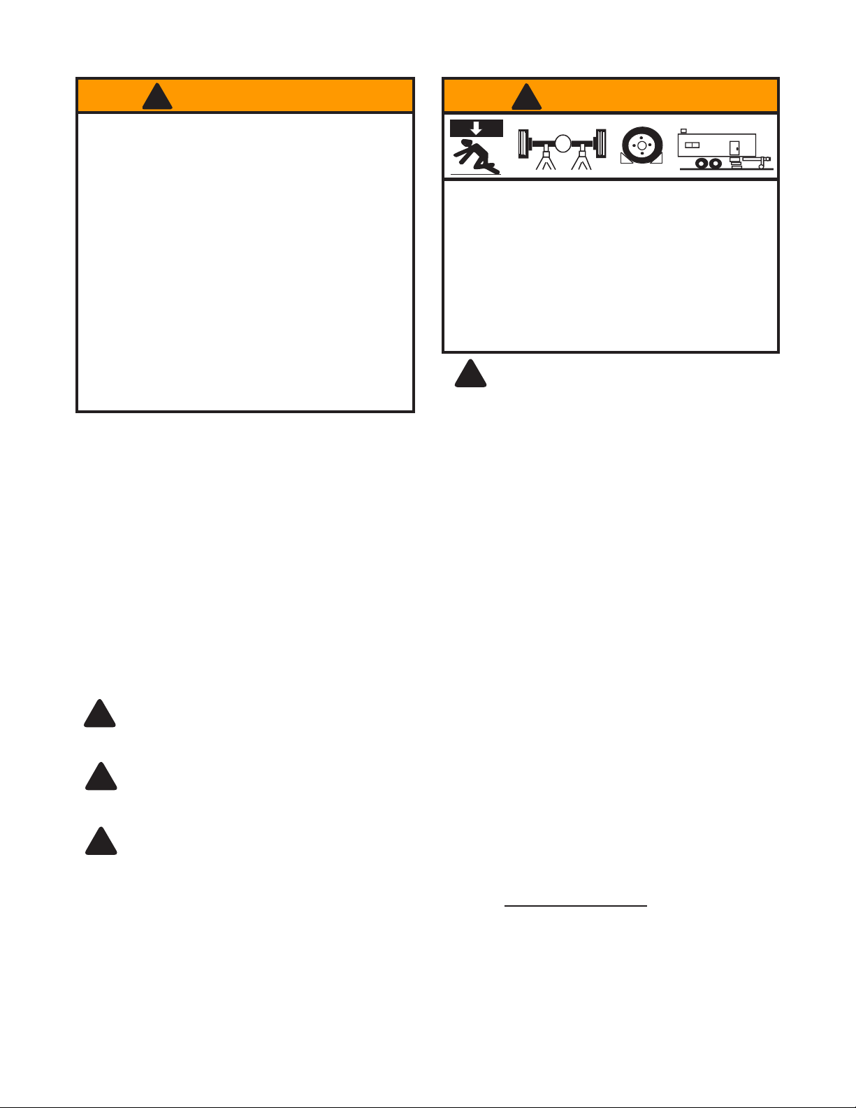
! WARNING
X
To avoid crushing and related injuries:
•
Never work on, under or around a load supported
only by hydraulic jack.
•
Always use adequately rated jack stands.
• Chock each unlifted tire in both directions.
• Do not use this device to lift, level, lower, support nor
move a house, mobile home, travel trailer, camper or
any building structure.
• Be alert and sober when using this product. Do not
operate under the inuence of drugs or alcohol.
Be sure all tools and personnel are clear
!
before lowering load. Only attachments and/or
adapters supplied by the manufacturer shall be used.
Lift only on areas of the vehicle as specied by the
vehicle manufacturer.
OPERATION
Raising the Ram Plunger
1. Assemble handle, ensure that spring clips align with slots.
2. Place vehicle in the park, with emergency brake on and wheel securely chocked to prevent inadvertent vehicle
movement.
3. Locate and close release valve by turning handle clockwise until rm resistance is felt to further thread
engagement.
4. Verify lift point, center jack saddle under lift point.
5. Squeeze the lift control valve in order to raise saddle to contact lift point. To lift, continue pumping until load
reaches desired height.
6. Immediately secure lifted load with appropriately rated jack stands.
Use only the handle provided by jack manufacturer. The handle provided with this jack will safely engage
!
the release valve. If handle is worn, operates abnormally, or will not positively engage the release valve,
STOP, discontinue use of the jack until a factory replacement handle can be acquired.
Do not use an extender on the air hose or the operating handle.
!
Lowering
Make certain that all personnel are clear of the load before lowering. Control the rate of descent of the
!
load at all times. The more you open the release valve, the faster the load descends.
1. Raise load high enough to clear the jack stands, then carefully remove jack stands (always used in pairs).
2. Slowly turn the handle counter-clockwise, but no more than 1 turn. If the load fails to lower:
a. Use another jack to raise the vehicle high
enough to reinstall jack stands.
b. Remove the affected jack and then the stands.
c. Lower the load by turning the release valve counter-clockwise, but no more than 1 turn.
3. After removing jack from under the load, push ram and handle sleeve down to reduce exposure to rust and
contamination.
3
 Loading...