

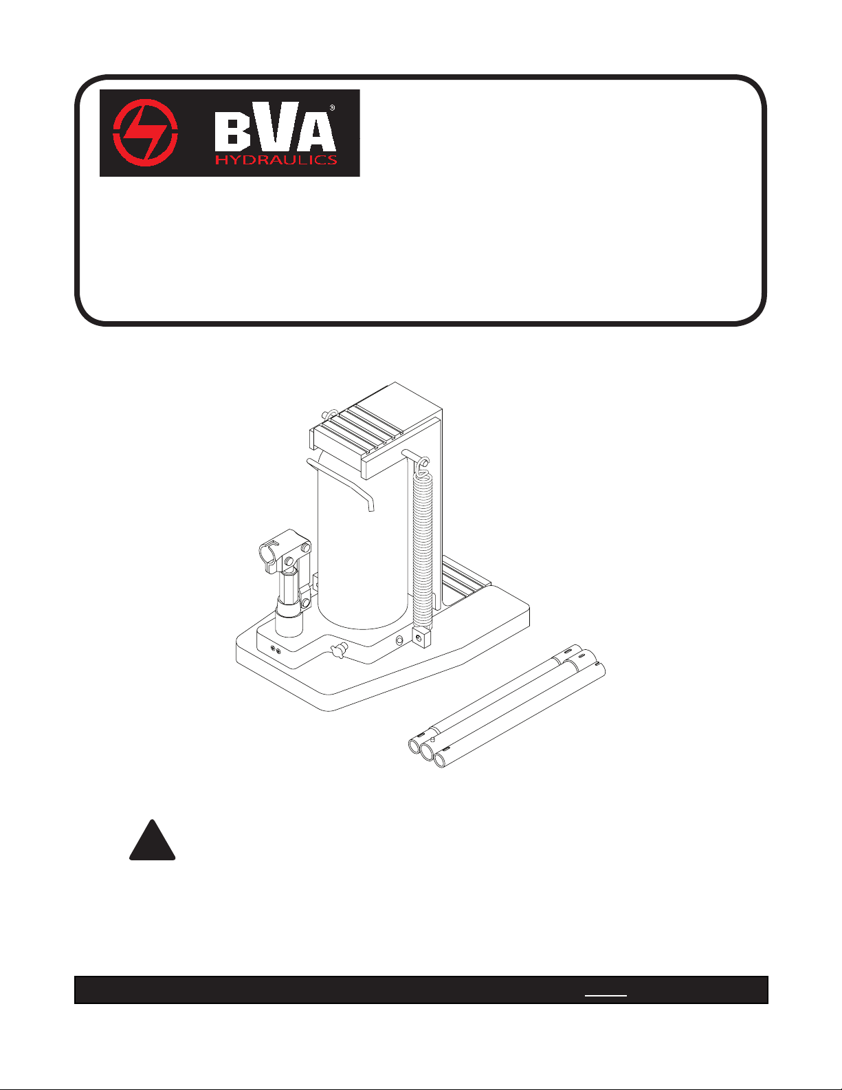
Toe Jack
Instruction Manual
MODELS: J13060 3-Ton
J13120 6-Ton
J13200 10-Ton
J13300 15-Ton
SFA Companies 10939 N. Pomona Ave. Kansas City, MO 64153
Tel: 888-332-6419 Fax: 816-891-6599
E-mail: sales@bvahydraulics.com Website: www.bvahydraulics.com
J13060-M2 092012
This is the safety alert symbol. It is used to alert you to potential personal injury hazards.
Obey all safety messages that follow this symbol to avoid possible injury or death.
!
Read this manual and follow all the Safety Rules and Operating Instructions before using this product.
Printed in Taiwan

SAFETY AND GENERAL INFORMATION
Save these instructions. For your safety, read, understand,
and follow the information provided with and on this device
before using. The owner and/or operator shall have an
understanding of the device, its operating characteristics and
safety operating instructions before operating the equipment.
The owner and/or operator shall be aware that use and repair
of this product may require special skills and knowledge.
Instructions and safety information shall be read to and
discussed with the operator in the operator's native language,
making sure that the operator comprehends their contents,
before use of this equipment is authorized. If any doubt exists
as to the safe and proper use of this device, remove from
service immediately.
Inspect before each use. Do not use if abnormal conditions
such as cracked welds, damaged, loose or missing parts are
noted. Any equipment that appears damaged in any way, is
found to be worn, or operates abnormally shall be removed
from service until repaired. If the equipment has been or is
suspected to have been subjected to an abnormal load or
shock, immediately discontinue use until inspected by a factory
authorized repair facility (contact distributor or manufacturer
for list of authorized repair facilities). It is recommended
that an annual inspection be made by an authorized repair
facility. Labels and Operator's Manuals are available from
the manufacturer.
PRODUCT DESCRIPTION
This product is designed to lift, position, or move, but not
sustain, rated capacity loads. It is not designed to be used as
a stand-alone device. Any load lifted, positioned, or otherwise
moved by this device, must immediately be supported by
appropriately rated mechanical means. A wide variety of
applications exist for this category of product. Special skill,
knowledge and training may be required for a specic task and
this product may not be suitable for all jobs listed. Unsuitable
applications include applications that call for a device to
lift, position, move or support persons, animals, hazardous
materials, mobile homes and dwellings in general, mirrors,
plate glass or to connect/secure hatches, components, and
materials between bulkheads. The user ultimately must make
the decision regarding suitability of the product for any given
task and therefore accept responsibility for that decision.
TECHNICAL SPECIFICATIONS
J13060 rated capacity: 6,000 lbs. (3 tons)
J13120 rated capacity: 12,000 lbs. (6 tons)
J13200 rated capacity: 20,000 lbs. (10 tons)
J13300 rated capacity: 30,000 lbs. (15 tons)
Hydraulic Pressure @ rated capacity:
J13060: 4185 psi
J13120: 4000 psi
J13200: 5400 psi
J13300: 7750 psi
!
WARNING
• Study, understand, and follow all instructions before
operating this device.
• Do not exceed rated capacity.
• Use only on hard level surfaces.
• Lifting device only. Immediately after lifting, support
load with appropriate means.
• Lift only on those areas of a vehicle as specified by the
vehicle manufacturer.
• No alterations shall be made to this product.
• Only attachments and/or adapters supplied by the
manufacturer shall be used.
• Failure to heed these markings may result in personal
injury and/or property damage.
PREPARATION
Before Use
1. Before using this jack, read the operator's manual completely
and familiarize yourself thoroughly with the product, its
components and recognize the hazards associated with
its use.
2. Verify that the product and application are compatible.
3. Assemble handle, ensure spring clips align with slots.
Replace reservoir oil plug with Vent Screw provided
4. To familiarize yourself with basic operation, use the notched
end of provided Pump Handle to engage and turn the
Release Valve:
a. Clockwise until rm resistance is felt to further turning.
This is the ‘CLOSED’ Release Valve position used to
raise the ram plunger.
b. Counter-clockwise, but no more than 1/2 turn from
the closed position. This is the ‘OPEN’ Release Valve
position used to lower the Ram Plunger.
5. With Ram Plunger fully retracted and release valve closed,
pump the operating handle. If Ram Plunger responds
immediately, jack is ready for use. If jack does not respond,
follow Bleeding/Venting Trapped Air instruction below.
6. Check that the pump operates smoothly and that the
Extension Screw will thread up/down easily before
putting into service. Replace worn or damaged parts and
assemblies with Omega authorized replacement parts only.
Bleeding/Venting Trapped Air
With the Release Valve in the OPEN position (step 4b above)
and with Ram Plunger fully lowered, locate and remove the
Oil Filler Plug/Screw. Insert the Pump Handle into the Handle
Sleeve; then pump 6 to 8 full strokes. This will help release
any pressurized air which may be trapped within the reservoir.
Oil level should be even with the bottom of the oil ller hole.
Reinstall oil reservoir Vent Screw.
2
SPECIFICATIONS
Model Capacity
J13060 3 Ton 8-5/8 x 7-1/2 5/8" / 5-3/4" 9" / 14-1/8" 5-1/8"
J13120 6 Ton 11 x 7-1/2 7/8" / 6" 10-1/2" / 15-5/8" 5-1/8"
J13200 10 Ton 11-5/8 x 9-1/4 1-1/8" / 6-1/4" 11" / 16-1/8" 5-1/8"
J13300 15 Ton 12-1/2 x 10-3/4 1-1/8" / 6-5/8" 13-1/8" / 18-5/8" 5-1/2"
Base Size
(l" x w")
Head Saddle
Toe Saddle
Min. / Max Height
Head Saddle
Min. / Max. Height
Hydraulic
Lift
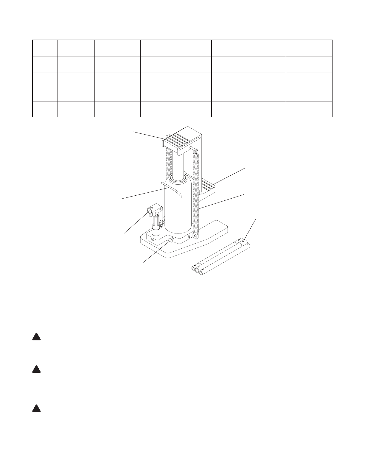
Oil Filler Plug/Screw (ref.
Parts illustration for location)
Carry Handle
Handle Sleeve
Release Valve
Toe Saddle
Return Spring
Handle
Figure 1 - Typical Toe Jack Components
OPERATION
Raising the Ram Plunger
1. Use the handle to engage and turn the release valve clockwise until rm resistance is felt to further thread engagement.
2. Pump until load reaches desired height. Immediately secure with appropriately rated mechanical devices.
It is recommended you follow the load with cribbing and blocking where practical.
WARNING: Never allow personnel to work or pass under a load until the load is secured by cribbing, blocking, or other
!
mechanical means.
Lowering
WARNING: Clear all personnel and tools before lowering load. Control the rate of descent of the load at all times. The
!
more you open the release valve, the faster the load will descend.
1. Use the manufacturer's provided operating handle to engage and slowly turn the release valve counter-clockwise, but no more
than 1 turn.
WARNING: If the operating handle is damaged, operates abnormally, or will not positively engage the release valve,
!
immediately discontinue use of the jack until a manufacturer's replacement handle assembly can be acquired.
2. Push ram down and handle sleeve in to reduce exposure to rust and contamination after removing jack from under load.
3
MAINTENANCE
NOTICE: Use premium quality hydraulic jack oil. Avoid mixing different types of uid and NEVER use brake uid, turbine oil,
transmission uid, motor oil or glycerin. Improper uid can cause premature failure of the jack and the potential for sudden and
immediate loss of load.
Adding Oil
1. With saddle fully lowered set jack in its upright, level position. Locate and remove oil ller plug/screw.
2. Fill with oil even with the bottom of the oil ller hole. Reinstall the oil ller plug/screw.
Changing Oil
For best performance and longest life, replace the complete uid supply at least once per year.
1. With saddle fully lowered set jack in its upright, level position. Locate and remove oil ller plug/screw.
2. Lay the jack on its side and drain the uid into a suitable container.
NOTICE: Dispose of hydraulic uid in accordance with local environmental regulations.
3. Fill with oil even with the bottom of the oil ller hole. Reinstall the oil ller plug/screw.
Lubrication
A periodic coating of light lubricating oil to pivot points will help to ensure that pump piston linkages move freely. Do not apply
oil to saddle area.
Cleaning
Periodically check the pump piston and ram plunger/saddle for signs of rust or corrosion. Clean as needed and wipe with a clean,
oil soaked rag. Do not apply oil to saddle area.
Storage
Store the jack with pump piston, ram plunger/saddle fully lowered and release valve open, but never more than 1 turn. This will
help prevent rust and corrosion to those critical surfaces.
WARNING: The paint on this product contains lead, a chemical known in the State of California to cause cancer, birth
!
defects and other reproductive harm. Do not ingest paint chips and keep product away from children. Wash hands after
each use.
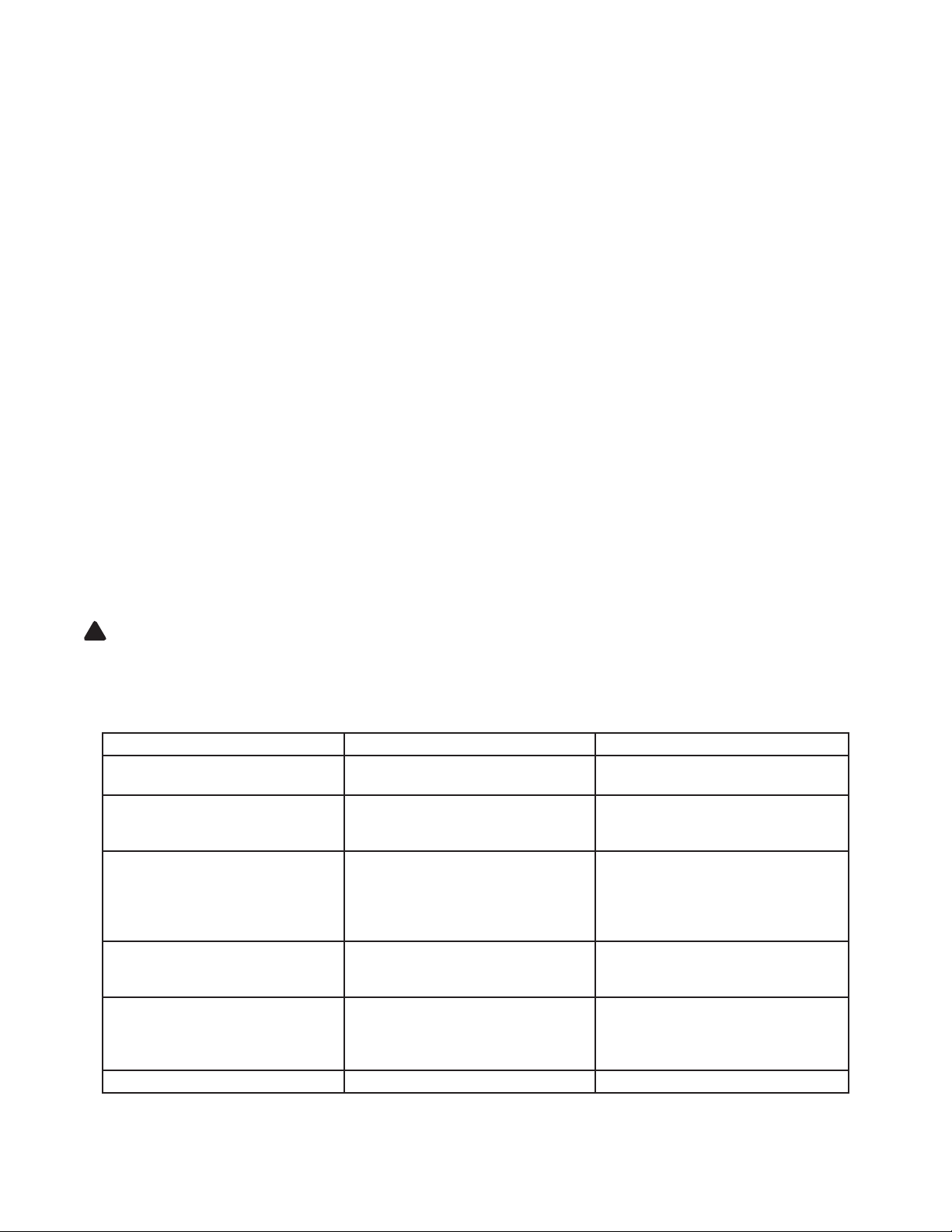
TROUBLESHOOTING
Symptom Possible Causes Corrective Action
Jack will not pressurize
Jack bleeds off after lift
(load slowly and unintentionally
lowers)
While lowering, uid leaks from
reservoir area.
Jack saddle will not descend to lowest advertised height.
Ram plunger will not remain lowered
after released from contact with load
(creeps back up)
Poor lift performance
Will not lift to full extension • Fluid level low • Ensure proper uid level
• Release valve not tightly closed
• Load is too heavy
• Hydraulic unit malfunction • Contact Service Center
• Reservoir overlled
• Ram plunger/cylinder deformed,
seized up in ram cylinder and/or
top nut, likely the result of off-center
loading
• Air trapped in system • Perform Bleeding/Venting Trapped
• Fluid level low
• Air trapped in system
• Hydraulic unit malfunction
• Ensure release valve tightly closed
• Consider higher capacity jack
• Drain uid to proper level
• Contact Service Center
Air procedure.
• Ensure proper uid level
• Perform Bleeding/Venting Trapped
Air procedure.
• Contact Service Center
4
 Loading...