

IAP5506-M0_092013
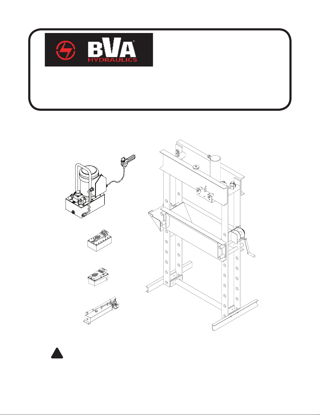
Rolling Head Shop Press
Instruction Manual
MODELS: IMPR5506, IAPR5506, IEPR5506, IEPRS5506, IAPR5513, IEPR5513,
IEPRS5513, IAPDR5506, IEPDR5513, IEPDRS5513
SFA Companies 10939 N. Pomona Ave. Kansas City, MO 64153
Tel: 888-332-6419 * Fax: 816-891-6599
E-mail: sales@bvahydraulics.com Website: www.bvahydraulics.com
Max. Operating Pressure 10,000 PSI
This is the safety alert symbol. It is used to alert you to potential personal injury hazards.
!
Obey all safety messages that follow this symbol to avoid possible injury or death.
Printed in USA
SAFETY AND GENERAL INFORMATION
Save these instructions. For your safety, read, understand, and follow the information provided with and on this
device before using. The owner and/or operator shall have an understanding of the device, its operating characteristics
and safety operating instructions before operating the equipment. The owner and/or operator shall be aware that use
and repair of this product may require special skills and knowledge. Instructions and safety information shall be read
to and discussed with the operator in the operator’s native language, making sure that the operator comprehends
their contents, before use of this equipment is authorized. If any doubt exists as to the safe and proper use of this
device, remove from service immediately.
Inspect before each use. Do not use if abnormal conditions such as cracked welds, damaged, loose or missing
parts are noted. Any equipment that appears damaged in any way, is found to be worn, or operates abnormally shall
be removed from service until repaired. If the equipment has been or is suspected to have been subjected to an
abnormal load or shock, immediately discontinue use until inspected by a factory authorized repair facility (contact
distributor or manufacturer for list of authorized repair facilities). It is recommended that an annual inspection be
made by an authorized repair facility. Labels and Operator’s Manuals are available from the manufacturer.
PRODUCT DESCRIPTION
BVA Hydraulics Shop presses are designed for automotive, truck, implement, eet, and industrial repair shops where
pressing, bending, straightening, forming, holding is required. Each press includes a cylinder, an electric pump with
pendant switch, a winch assembly which provides safe and fast way to raise and lower the bed frame, and a pressure
gauge which provides for monitoring the applied press force. Typical applications include installation and removal of
alternator and power steering pump bearings, axle bearings, transmission bearings, seal, driveshaft bearings and
u-joints and others. It is not intended for use as an assembly table or as xture stand used to secure a large, nal
assembly component. Please refer to Cylinder and Pump manuals for more information.
! WARNING
• Study, understand, and follow all instructions provided with and on this device before use.
• Do not exceed rated capacity.
• Prior to use, make sure press is securely anchored.
• The press shall be installed and operated in accordance with federal (OSHA), state and local safety stand-
ards.
• Operators and observers shall wear eye protection that meets ANSI Z87.1 and OSHA standards.
• Keep hands, arms, feet and legs out of the work area. Accidental slippage can result in personal injury.
• Use appropriate guarding to contain any pieces that may break or y apart when applying force.
• Use only press accessories having a capacity rating equal to or greater than the capacity of the press.
• Verify lift cables are slack before pressing on the bolster.
• Avoid off-center loads.
• No alterations shall be made to the product.
• Failure to heed and understand these instructions and markings may result in personal injury, property dam-
age or both.
WARNING: To reduce the risk of personal injury and/or property damage, ensure that the rated working
!
pressure of each pressurized attachment is equal to or greater than the rated working pressure developed by
the hydraulic pump.
NOTICE: The power retract feature of the IAPDR5506, IEPDR5513 and IEPDR5513S Shop Press models is not
intended to be used under load. Never pull or raise a workpiece with the power retract feature.
2

SPECIFICATIONS
Press
Model
IMPR5506
IAPR5506 PA2000
IEPR5506 PEW0501T
IEPRS5506 PESL0501T
IAPDR5506 HD5506 PA3801M
IAPR5513
IEPR5513 PEW0501T
IEPR5513S
IEPDR5513 PEWM1002T
IEPDRS5513 PESML1002T
Cylinder
Model
H5506
Rated
Capacity
55 Ton
Rated
Capacity
(ton)
Cylinder
Model
H5506
H5513
HD5513
Stroke
(in.)
6.22
Model/Type
PESL0501T
Effective
Area
(in3)
Pump
P2001
PA2000
Oil Volume
(in
68.34 11.14 17.36
Press Bed
Depth
(front to back)
14-7/8” 35-1/2” 79-1/8 x 56 x 30 14 55-1/2
Cylinder
3
Height
)
Min
(in.)
Press
Width
(side to side)
Max
Height
(in.)
Bed
Outer
Dia.
(in.)
Press Size
(H” x W” x L”)
Ram
Dia.
(in.)
3.15
Saddle
Dia.
(in.)
Min.
Height
(in.)
Collar
Thread
(in.)
Max.
Height
(in.)
Collar
Thread
Length
(in.)
2.17
HD5506 6.18 67.93 13.03 19.21 3.74 1.73
H5513 13.27 145.77 18.15 31.42 3.15 2.17
HD5513 13.19 144.94 20.04 33.23 3.74 1.73
55
10.99
5
2.76 5”-12
Manual Pump (Hand pump)
Hand Pump
Model
P2001 122 200 10,000 0.81 0.14 3/8”-18 NPTF 24
Usable Oil Volume
(in3)
Pressure Rating
(psi)
1st Stage 2nd Stage 1st Stage 2nd Stage
Oil Displacement
(in3)
Oil Outlet
Port
Thread
Weight
(lbs)
Air Pump
Air Pump
Model
PA2000 122.1
PA3801M 232 11 30
Usable Oil Volume
(in3)
Pressure Rating
(psi)
10,000 65
Oil Output Flow
Rate (in3/min)
No Load Load
12
Input Air Pressure
Range
(psi)
110 - 175
Weight
(lbs)
20
Electric Pump
Electric
Pump
Model
PEW0501T
PESL0501T
PEWM1002T
PESML1002T 311 73
Reservoir
Capacity
(gal)
1 350
2 700
Pressure Rating
(psi)
1st Stage 2nd Stage 1st Stage 2nd Stage
10,000
Oil Output Flow Rate
(in3/min)
293 18
397
37
Valve
Type
3-way,
3-pos
4-way,
3-pos
Motor
Size
(hp)
0.5 9
1 12
Current
Draw
(A)
Motor
Voltage
(V)
115
Weight
(lbs)
60
71
3
 Loading...