


IAP5506-M0_022013
Shop Presses
Instruction Manual
MODELS: IAP5506, IEP5506, IMP5506, IAP5513, IEP5513, IEPD5513,
IEP10010, IAP10010, IEPD10010 & IEPDS10010
SFA Companies 10939 N. Pomona Ave. Kansas City, MO 64153
Tel: 888-332-6419 * Fax: 816-891-6599
E-mail: sales@bvahydraulics.com Website: www.bvahydraulics.com
Max. Operating Pressure 10,000 PSI
Models IAP5506, IEP5506, IMP5506,
IAP5513, IEP5513 & IEPD5513
This is the safety alert symbol. It is used to alert you to potential personal injury hazards.
!
Obey all safety messages that follow this symbol to avoid possible injury or death.
Models IEP10010, IAP10010, IEPD10010 &
IEPDS10010
Printed in USA
SAFETY AND GENERAL INFORMATION
Save these instructions. For your safety, read and understand the information contained within. The owner and operator shall
have an understanding of this product and safe operating procedures before attempting to use this product. Instructions and
safety information shall be conveyed in operator’s native language before use of this product is authorized. Make certain that the
operator thoroughly understands the inherent dangers associated with the use and misuse of the product. If any doubt exists as
to the safe and proper use of this product as outlined in this factory authorized manual, remove from service immediately.
Inspect before each use. Do not use if broken, bent, cracked or otherwise damaged parts are noted. If any component of this
product has been or suspected to have been subjected to a shock load (a load dropped suddenly, unexpectedly upon it), discontinue
use until checked out by a BVA Hydraulics Authorized Service Center. Owners and operators of this equipment shall be aware
that the use and subsequent repair of this equipment may require special training and knowledge. It is recommended that an
annual inspection be done by qualied personnel and that any missing or damaged parts, decals, warning / safety labels or signs
be replaced with factory authorized replacement parts only. Any component of this Equipment that appears to be damaged in any
way, is worn or operates abnormally shall be removed from service immediately until such time as it can be repaired/replaced.
Labels and Instruction Manuals are available from manufacturer.
PRODUCT DESCRIPTION
BVA Hydraulics Shop presses are designed for automotive, truck, implement, eet, and industrial repair shops where pressing,
bending, straightening, forming, holding is required. Each press includes a cylinder, an electric pump with pendant switch, a
winch assembly which provides safe and fast way to raise and lower the bed frame, and a pressure gauge which provides for
monitoring the applied press force.
Typical applications include installation and removal of alternator and power steering pump bearings, axle bearings, transmission
bearings, seal, driveshaft bearings and u-joints and others. It is not intended for use as an assembly table or as xture stand used
to secure a large, nal assembly component. Please refer to Cylinder and Pump manuals for more information.
WARNING: To reduce the risk of personal injury and/or property damage, ensure that the rated working pressure of
!
each pressurized attachment be equal to or greater than the rated working pressure developed by the hydraulic pump.
NOTICE: The power retract feature of the IEPD5513, IEPD10010 & IEPDS10010 Shop Presses is not intended to be used
under load. Never pull or raise a workpiece with the power retract feature.
! WARNING
• Study, understand, and follow all instructions provided with and on this device before use.
• Do not exceed rated capacity.
• Prior to use, make sure press is securely anchored.
• The press shall be installed and operated in accordance with federal (OSHA), state and local safety standards.
• Operators and observers shall wear eye protection that meets ANSI Z87.1 and OSHA standards.
• Keep hands, arms, feet and legs out of the work area. Accidental slippage can result in personal injury.
• Use appropriate guarding to contain any pieces that may break or y apart when applying force.
• Use only press accessories having a capacity rating equal to or greater than the capacity of the press.
• Verify lift cables are slack before pressing on the bolster.
• Avoid off-center loads.
• No alterations shall be made to the product.
• Failure to heed and understand these instructions and markings may result in personal injury, property dam-
age or both.
BEFORE USE
1. Inspect before each use. Do not use if bent, broken or cracked components are noted. Check for and tighten any loose assemblies.
2. Verify that the product and the application are compatible, if in doubt call BVA Technical Service.
3. Before using this product, read the operator’s manual completely and familiarize yourself thoroughly with the product, its components and recognize the potential hazards associated with its use.
2

SPECIFICATIONS
Press
Model
IMP5506
IAP5506 PA2000/air-hydraulic
IEP5506 PEW0501T/electric
IAP5513
IEP5513 PEW0501T/electric
IEPD5513 HD5513 PEWM0501T/electric
IAP10010
IEP10010 PEW1002T/electric
IEPD10010
IEPDS10010 PESML1002T/electric
Rated
Capac-
ity
55 Ton
100 Ton
Cylinder
Model
H5506
H5513
H10010
HD10010
Pump
Model/Type
P2001/manual
PA3801/air-hydraulic
PA7550
PEWM1002T/electric
Press Bed
Depth
14-7/8” 35-1/2” 79-1/8 x 56 x 30 14 55-1/2
16-1/4” 35-3/8” 89-1/2 x 63 x 30 11-1/4 52
Press
Bed
Width
Press Size
(H” x W” x L”)
Cylinder
Cylinder
Model
H5506
H5513 13.27 145.77 18.15 31.42
HD5513 13.19 144.94 20.04 33.23 3.74
H10010
HD10010 10.13 208.3 27.80 3.74 2.95 2.00
Rated
Capacity
(ton)
55
100
Stroke
(in.)
6.22
10.24
Effective
Area
(in3)
10.99
20.57
Oil Vol-
ume
3
(in
68.34 11.14 17.36
210.6
Min
Height
)
(in.)
17.68
Max
Height
(in.)
27.93
Outer
Dia.
(in.)
5
6.97
Ram
Dia.
(in.)
3.15
4.13
Saddle
Dia.
(in.)
2.76
Min.
Work
Height
(in.)
Collar
Thread
(in.)
5”-12
6-7/8”-12
Height
Collar
Thread
Length
Max.
Work
(in.)
(in.)
2.17
1.73
Hand Pump
Model
P2001 122 200 10,000 0.81 0.14 3/8”-18 NPTF 24
Air Pump
Model
PA1500 91.5
PA3801 232 27
PA7550 460.6 36
Electric
Pump
Model
PEW0501T
PEWM0501T
Manual Pump (Hand pump)
Usable Oil Volume
(in3)
Pressure Rating
(psi)
1st Stage 2nd Stage 1st Stage 2nd Stage
Air Pump
Usable Oil Volume
(in3)
Pressure Rating
(psi)
10,000 65 11 90-175
Electric Pump
Reservoir
Capacity
(gal)
1 350 10,000 293 18
Pressure Rating
(psi)
1st Stage 2nd Stage 1st Stage 2nd Stage
Oil Output Flow Rate
(in3/min)
Oil Displacement
(in3)
Oil Output Flow
Rate (in3/min)
No Load Load
Valve
Type
3-way,
3-pos
4-way,
3-pos
Oil Outlet
Port
Thread
Input Air Pressure
Range
(psi)
Motor
Current
Size
(hp)
0.5 9 115/125 60
Draw
(A)
Weight
(lbs)
Weight
(lbs)
18
Motor
Voltage
(V)
Weight
(lbs)
3
Electric Pump (con’t)
PEW1002T
PEWM1002T
PESML1002T 311 73
2 700 10,000
397
37
3-way,
3-pos
4-way,
3-pos
1 12 115/125
71
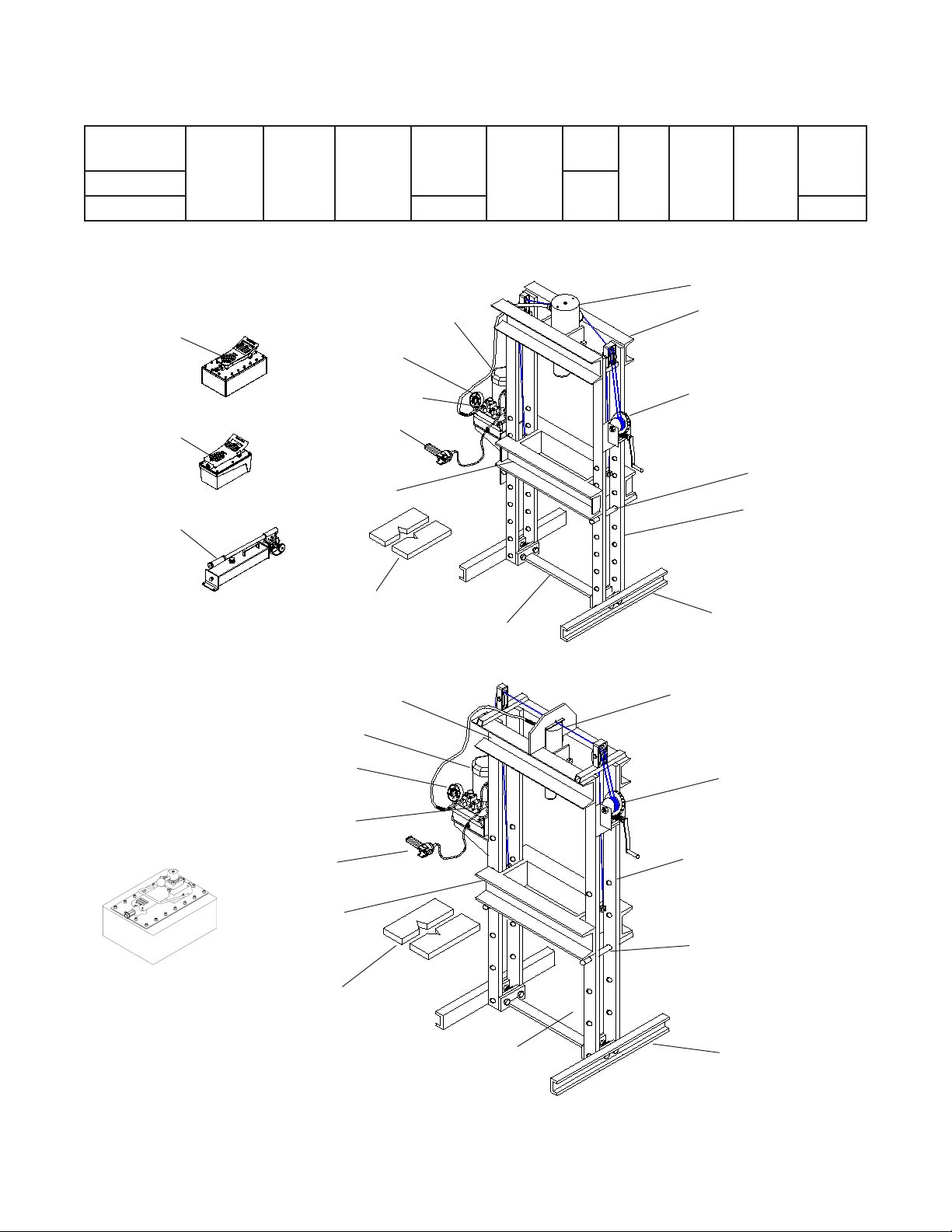
Air Pump for
Model IAP5513
Air Pump for
Model IAP5506
Hand/ Manual Pump
for Model IMP5506
Electric Pump for Model
IEP5506, IEP5513 &
Pressure Gauge
Control Valve Knob
Pendant Switch
Bed Frame
Arbor Plates
(purchased separately)
Figure 1 - Components for 55 Ton Press.
Upper Cross Member
Electric Pump
IEPD5513
Lower Cross Member
Cylinder
Upper Cross Member
Winch
Support Pin
Upright Channel
Base
Channel
Cylinder
Air Pump for Model
IAP10010
(purchased separately)
Pressure Gauge
Control Valve Knob
Pendant Switch
Bed Frame
Arbor Plates
Figure 2 - Components for 100 Ton Press (Model IEP10010)
Lower Cross
Member
4
Winch
Upright Channel
Support Pin
Base
Channel

ASSEMBLY
1. Ensure bed frame at lowest position and winch cable is slack.
2. Install the winch assembly to the press using 3 bolts, washers and nuts (ref. Figs 2 & 3).
3. Secure cylinder to cylinder adapter plate, and mount the adapter plate to upper cross member using 4 bolts and washers.
NOTICE: The cylinder comes with carrying handles, simply loosen the Allen head socket screw to remove the handles.
4. Attach base sections to upright channels with 4 bolts and nuts.
5. Attach lower cross member to upright channels with 4 bolts and nuts.
6. For 55 Ton Models only: adjust the pump bracket to desired height and secure with bolts, nuts & washers provided.
7. Connect pressure gauge and hydraulic hose to the gauge adapter, then connect the gauge adapter to pump.
8. For Models IEPD5513, IEPD10010 & IEPDS10010 only: Attach second hose to Port B on Control Valve. Attach second coupler
to free hose end. Connect coupler to bottom port on Cylinder.
NOTICE: Ensure thread tape or compound is used on connections.
8. Place the pump on the pump bracket and connect the other end of hydraulic hose to cylinder.
CAUTION: Before disassembling, slide bed frame section down to its lowest position.
!
OPERATION
WARNING: Shop presses can present a projectile hazard. Ensure workpiece is center loaded and secure. Reduce
!
risk of ying debris by following all operating instructions. Know your press and hazards associated with its use.
Keep hands and feet from bed area at all times.
WARNING: Risk of serious eye injury from projected or blown debris. Reduce risk by wearing safety goggles when working
with or around press.
1. Insert the support pins to desired height, then lower the bed frame using the winch until the cable is slack and the bed frame
is resting fully on the support pins.
2. Place arbor plates on the bed frame (optional).
3. Place workpiece on bed frame, using every precaution necessary to ensure your safety and prevent property damage.
4. Operate the pump:
a) For Model IMP5506 (manual): Close the release valve by turning it clockwise, and pump the handle to extend the cylinder
ram. To retract, simply open the release valve of pump.
b) For Models IAP5506, IAP5513 & IAP10010 (air): Connect to suitable air supply, press on the foot pedal to extend the
cylinder ram. To retract, simply press the release valve by stepping on the raised, stirrup shaped portion of the foot pedal.
c) For Models IEP5506, IEP55513, IEPD5513, IEP10010, IEPD10010 & IEPDS10010 (electric): Toggle the ON/OFF switch
to start the electric pump and let the pump idle for a few minutes before putting into operation. Use control valve knob to
extend or retract the cylinder ram.
WARNING: Burst hazard exists if hose or connection pressure exceeds rated pressure. Always monitor the pressure
!
gauge while in operation and never leave loaded press unattended.
NOTICE: The power retract feature of the IEPD5513, IEPD10010 & IEPDS10010 Shop Presses is not intended to be used
under load. Never pull or raise a workpiece with the power retract feature.
NOTICE: Never operate pump with hose disconnected from cylinder. If operated in this condition, the hydraulic hose and connections become pressurized. This increases burst hazard.
5. Apply load to workpiece. Do not overload the workpiece.
6. Stabilize workpiece in a manner which will not allow it to inadvertently fall from the bed once the load is removed.
7. Once cylinder has fully retracted, remove workpiece.
NOTICE: To protect your cylinder, do not continue to operate pump after cylinder plunger is fully extended or retracted.
5

MAINTENANCE
Please refer to cylinder and pump’s manuals for maintenance and how to add/change hydraulic oil. For best results, change the
oil once a year. Use only good quality hydraulic oil. Mobil DTE13M or equivalent is recommended for manual and air pumps, BVA
hydraulic oil or equivalent for electric pump.
Lubrication
A periodic coating of light lubricating oil to pivot points and hinges will help to prevent rust and assure assemblies move freely.
Storage
Depressurize the hydraulic system, disconnect the hydraulic hose and lower the bed frame to lowest position. Disconnect
both hoses on the IEPD5513, IEPD10010 & IEPDS10010 Double Acting Shop Presses.
TROUBLESHOOTING
A system failure may or may not be the result of a pump malfunction. The following information is intended to be used as an
aid in determining if a problem exist.
Symptom Possible Causes Corrective Action
• Air in system or pump cavitation
Erratic Ram Performance
Pump or ram fails to maintain
pressure
Ram extends partially
Slow ram movement
Ram leaks hydraulic uid • Worn or damaged seals • Contact Service Center
Ram will not retract or retracts
slower than normal
Motor will not start (for Model
IEP5506, IEP5513, IEPD5513,
IEP10010, IEPD10010, & IEPDS10010)
Motor cuts out (for Model
IEP5506, IEP5513, IEPD5513,
IEP10010, IEPD10010 &
IEPDS10010)
• External leak
• Internal hydraulic leak
• Overload condition
• External leak
• Internal hydraulic leak
• Ram seals leaking
• Pump or valve malfunctioning
• Hydraulic oil level too low in pump
• Load is above the capacity of system
• Ram is sticking or binding
• Loose connection or coupler
• Restricted hydraulic line or tting
• Pump not working correctly
• Ram seals leaking
• Linkage binding
• Loose couplers
• Malfunctioning coupler
• Weak or broken retraction springs
• Ram damaged internally
• Pump reservoir too full
• No power or wrong voltage
• Damaged power cord
• Tripped circuit breaker
• Loose or faulty wiring
• Extension cord too long
• Faulty motor
• Overheated motor can trip circuit breaker
• Follow pump instructions for bleeding air
• Tighten all connections
• Contact Service Center
• Remedy overload condition
• Tighten all connections
• Contact Service Center
• Contact Service Center
• Check pump operating instructions
• Fill and bleed the system
• Match the capacity to application
• Contact Service Center
• Tighten connection or coupler
• Clean and replace if damaged
• Check pump operating instructions
• Replace cylinder
• Lubricate all moving parts
• Tighten couplers
• Depressurize pump and hose, remove ap-
plication, then replace a new coupler
• Contact Service Center
• Contact Service Center
• Drain hydraulic uid to correct level
• Check the power supply & voltage
• Contact Customer Service
• Make sure breaker is of adequate size
• Contact Customer Service
• Replace with shorter cord
• Replace or repair
• Allow motor to cool, reset circuit breaker
6

Shop Press
Service Parts
INCLUDES MODELS: IAP5506, IEP5506, IMP5506, IAP5513, IEP5513 & IEPD5513
SFA Companies 10939 N. Pomona Ave. Kansas City, MO 64153
Tel: 888-332-6419 * Fax: 816-891-6599
E-mail: sales@bvahydraulics.com Website: www.bvahydraulics.com
Note: Not all components of the press are replacement items, but are illustrated as a convenient reference of location and
position in the assembly sequence.
Parts Illustration
12
18
7
16
11
9
11
15
14
13
21
22
10
19
8
2
6
3
20
1
5
23
4
Figure 3- Replacement Parts Illustration for Models IAP 5506, IEP5506, IMP5506, IAP5513, IEP5513 & IEPD5513
7

Shop Presses
Service Parts
MODELS: IMP5506, IAP5506, IEP5506, IAP5513, IEP5513 & IEPD5513
SFA Companies 10939 N. Pomona Ave. Kansas City, MO 64153
Tel: 888-332-6419 * Fax: 816-891-6599
E-mail: sales@bvahydraulics.com Website: www.bvahydraulics.com
Note: Not all components of the press are replacement items, but are illustrated as a convenient reference of location and
position in the assembly sequence.
Parts List
Item
12a H5506 N/A H5506 N/A
12b N/A H5513 N/A H5513 N/A
12c N/A HD5513
IMP5506 IAP5506 IAP5513 IEP5506 IEP5513 IEPD5513
1 N/A
2 N/A Bed Frame 1
3 400-002-003 Support Pin 2
4 IEP-001-004 Frame Base Channel 2
5 IEP-001-005 Lower Cross Member 1
6 400-002-006 Winch 1
7 400-002-007 Cable Sheaves (Pulley) 3
8 400-002-008 Cable 2
9 IEP-001-009 N/A Hand Pump Platform Bracket 1
10 N/A IEP-001-011 Air/Electric Pump Bracket 1
11 IEP-002-012 Cylinder Adapter Plate 1
13 P2301 N/A Pump, Manual 1
14 N/A PA1500 N/A Pump, Air, 91.5 in
15 N/A PA3801 N/A Pump, Air, 232 in
16 N/A PEW0501T PEWM0501T Pump, Electric, 0.5 hp 1
17 300-002-016 N/A Pump Mounting Hardware Kit 1
18 N/A PEW01 Pendant Switch 1
19 CS3838 CS3838C CS3838 Hydraulic Hose 1*
20 CH38M Male Coupler 1*
21 GW4014 Pressure Gauge, 4”, Wet 1
22 CF3814 Gauge Adapter 1
23 AP55 Arbor Plates 1
Part No. for Model
Description Qty
Press Frame w/Winch and
Pump Brackets
Single Acting Cylinder, 55 Ton
6” Stroke
Single Acting Cylinder, 55 Ton
13” Stroke
Double Acting Cylinder, 55 Ton
13” stroke
3
3
1
1
1
1
1
1
* Qty 2 for IEPD5513 Double Acting Presses
8

Shop Presses
Service Parts
MODEL NUMBER: IAP10010, IEP10010, IEPD10010 & IEPDS10010
SFA Companies 10939 N. Pomona Ave. Kansas City, MO 64153
Tel: 888-332-6419 * Fax: 816-891-6599
E-mail: sales@bvahydraulics.com Website: www.bvahydraulics.com
Note: Not all components of the press are replacement items, but are illustrated as a convenient reference of location and
position in the assembly sequence.
Parts Illustration
9
7
10
11a
11b
13
12
16
15
14
18
8
6
2
3
1
5
4
17
Figure 4- Replacement Parts Illustration for Models IAP10010, IEP10010, IEPD10010 & IEPDS10010
9

Shop Presses
Service Parts
MODELS: IAP10010, IEP10010, IEPD10010 & IEPDS10010
SFA Companies 10939 N. Pomona Ave. Kansas City, MO 64153
Tel: 888-332-6419 * Fax: 816-891-6599
E-mail: sales@bvahydraulics.com Website: www.bvahydraulics.com
Note: Not all components of the press are replacement items, but are illustrated as a convenient reference of location and
position in the assembly sequence.
Parts List
Item
10a H10010 N/A Single Acting Cylinder, 100 ton, 10” Stroke 1
10b N/A HD10010 Double Acting Cylinder, 100 ton, 10” Stroke 1
11a PA7550 N/A Pump, Air, 460.6 in
11b N/A PEW1002T PEWM1002T PESML1002T Pump, Electric, 1 hp 1
12 N/A PEW01 N/A Pendant Switch 1
13 CS3838C CS3838 Hydraulic Hose 1*
14 CH38M Male Coupler 1*
15 GW4014 Pressure Gauge, 4”, Wet 1
16 CF3814 Gauge Adapter 1
17 AP100 Arbor Plates 1
18 IEP-001-011 Electric Pump Bracket 1
IAP10010 IEP10010 IEPD10010 IEPDS10010
1 N/A Press Frame w/Winch and Pump Bracket 1
2 N/A Bed Frame 1
3 610-002-003 Support Pin 2
4 IEP-002-004 Frame Base Channel 2
5 IEP-002-005 Lower Cross Member 1
6 400-002-006 Winch 1
7 400-002-007 Cable Sheaves (Pulley) 3
8 610-002-008 Cable 2
9 IEP-002-009 Cylinder Adapter Plate 1
Part No. for Model
Description Qty
3
1
* Qty 2 for IEPD10010 & IEPDS10010 Double Acting Presses
10

LIMITED LIFETIME WARRANTY
BVA Hydraulics®, represented in the United States by SFA Companies [“SFA”] warrants this product to be free from defects
in material and workmanship for the life of the product as long as the original purchaser owns the product. The warranty is
non-transferable and is subject to the terms, exclusions, and limitations described below:
• Damaged components, including but not limited to bent rams, dented or crushed cylinder walls, broken welds or couplers
as well as worn out seals, o-rings and springs are the result of misuse and not covered by warranty and BVA Hydraulics
will not provide any warranty credit for such damaged components.
• This warranty does not cover ordinary wear and tear, overloading, alterations (including repairs or attempted repairs not
performed by BVA Hydraulics or one of its authorized personnel), improper uid use, or use of the product in any manner
for which the product was not intended or the use of which is not in accordance with the instructions or warnings provided
with the product.
• In the unlikely event that a BVA Hydraulics product fails due to material defect in workmanship, you may contact SFA
Companies for disposition. In such cases, the customer’s sole and exclusive remedy for any breach or alleged breach of
warranty is limited to the repair or replacement of the defective product.
• Under no circumstances is BVA Hydraulics liable for any consequential or incidental damage or loss whatsoever.
• THIS WARRANTY IS LIMITED TO NEW PRODUCTS SOLD THROUGH AUTHORIZED DISTRIBUTORS AND OTHER
CHANNELS DESIGNATED BY BVA HYDRAULICS. NO AGENT, EMPLOYEE OR OTHER REPRESENTATIVE OF BVA
HYDRAULICS IS AUTHORIZED TO MODIFY THIS WARRANTY.
• THE FOREGOING IS EXCLUSIVE AND IS IN LIEU OF ALL OTHER EXPRESS AND IMPLIED WARRANTIES, INCLUDING
BUT NOT LIMITED TO THE IMPLIED WARRANTIES OF MERCHANTABILITY AND FOR A FITNESS FOR A PARTICULAR
PURPOSE.
• Components not manufactured by BVA Hydraulics including certain motor systems, gasoline engines, and other are not
covered by this warranty and instead are covered by the manufacturer’s separate manufacturer’s warranty provided in
the package.
• BVA Hydraulics’ liability in all cases is limited to, and will not exceed the purchase price paid for the product.
SFA Companies
10939 N. Pomona Ave. Kansas City, MO 64153
Tel: 888-332-6419
E-mail: sales@bvahydraulics.com
11

SFA Companies
10939 N. Pomona Ave. Kansas City, MO 64153
Tel: 888-332-6419
E-mail: sales@bvahydraulics.com
12
 Loading...