

Page 1
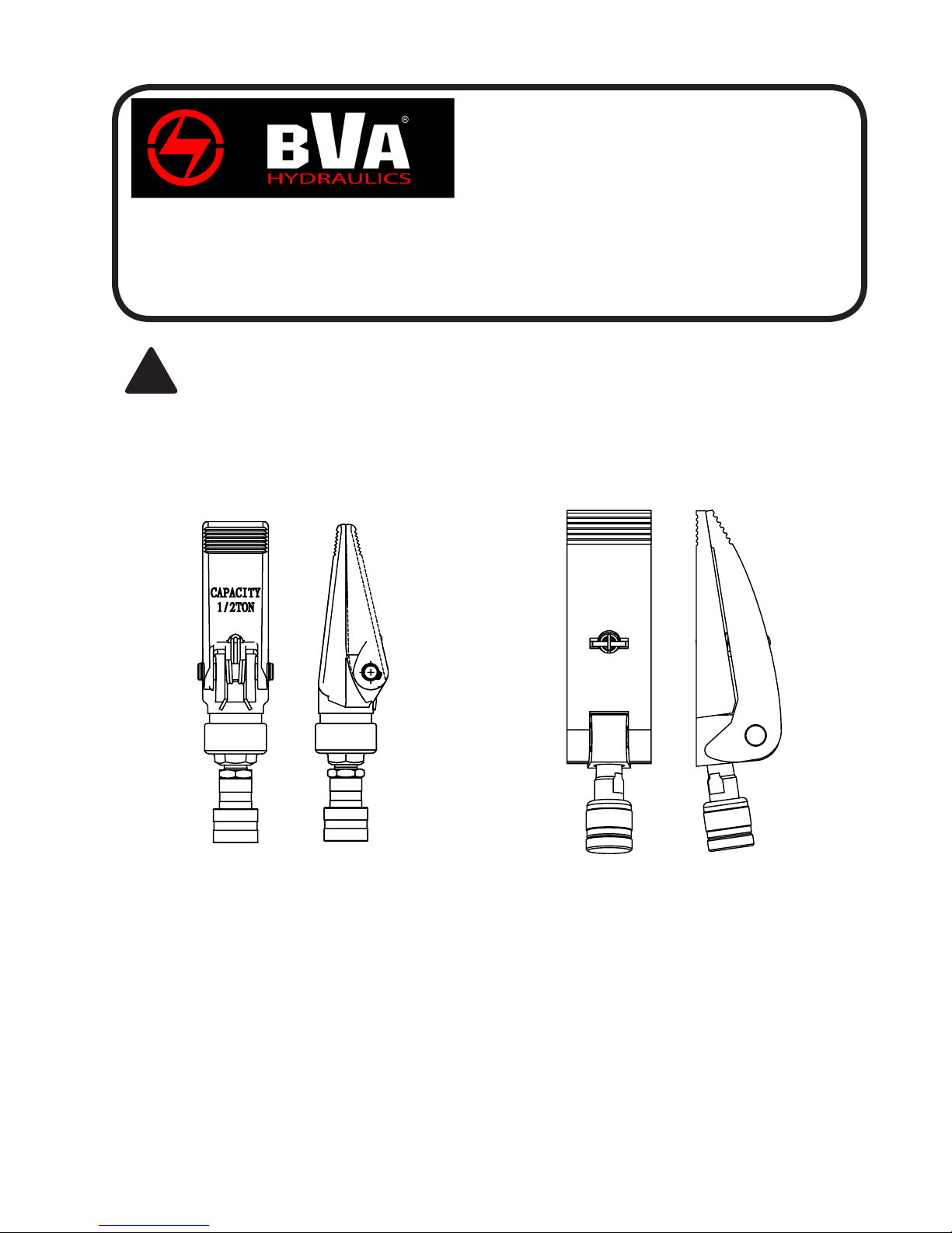
Hydraulic Spreader
Instruction Manual
MODEL NUMBERS: SR05 & SR10
SFA Companies 10939 N. Pomona Ave. Kansas City, MO 64153
Tel: 888-332-6419 * Fax: 816-891-6599
E-mail: [email protected] Website: www.bvahydraulics.com
This is the safety alert symbol. It is used to alert you to potential personal injury hazards.
!
Obey all safety messages that follow this symbol to avoid possible injury or death.
SR05-M0 ver 07/08
SR05
SR10
Printed in China
Page 2
Save these instructions. For your safety, read and
understand the information contained within. The owner and
operator shall have an understanding of this product and safe
operating procedures before attempting to use this product.
Make certain that the operator thoroughly understands the
inherent dangers associated with the use and misuse of the
product. If any doubt exists as to the safe and proper use of
this product as outlined in this factory authorized manual,
remove from service immediately.
Inspect before each use. Do not use if broken, bent,
cracked or otherwise damaged parts are noted. If any
component of this product has been or suspected to have
been subjected to a shock load (a load dropped suddenly,
unexpectedly upon it), discontinue use until checked out by
a BVA Hydraulics authorized service center. Owners and
operators of this equipment shall be aware that the use and
subsequent repair of this equipment may require special
training and knowledge. It is recommended that an annual
inspection be done by qualied personnel and that any
missing or damaged parts, decals, warning / safety labels or
signs be replaced with factory authorized replacement parts
only. Any spreader that appears to be damaged in any way, is
worn or operates abnormally shall be removed from service
immediately until such time as it can be repaired/replaced.
Instruction Manuals are available from manufacturer.
PRODUCT DESCRIPTION
BVA Hydraulic Spreaders are designed for rated capacity
pushing and spreading. A wide variety of applications exist
for this category of product.
Special skill, knowledge and training may be required for
a specic task and the product may not be suitable for all
the jobs described above. Unsuitable applications would
include applications that call for a device to move, level
or support persons, animals, hazardous materials, mobile
homes/dwellings in general, mirrors and/or plate glass, and/
or to connect/secure hatches, components, etc. between
bulkheads. The user ultimately must make the decision
regarding suitability of the product for any given task and
therefore accept responsibility for that decision. Immediately
after lifting, loads must be supported by appropriate
mechanical means.
NEVER rely upon a hydraulic spreader as a support
!
device! Immediately after lifting, loads must be
supported by appropriate mechanical means.
BEFORE USE
1. Before using this product, read the owner's manual
completely and familiarize yourself thoroughly with the
product, its components and recognize the hazards
associated with its use.
2. Verify that the product and the application are compatible.
If in doubt, call BVA Hydraulics Technical Service (888)
332-6419.
3. Inspect before each use. Do not use if bent, broken,
leaking or damaged components are noted.
4.
Replace worn or damaged parts and assemblies with BVA
Hydraulics authorized replacement parts only. Lubricate
as instructed in Maintenance Section.
5. Use ANSI compliant eye protection when operating or
near this equipment.
6. Ensure method of conrming load is accurate and working
properly. Have gauge or load cell accuracy veried by
qualied personnel on a yearly basis.
7. Spreaders should be stored where protected from the
elements, abrasive dust, and damage. These devices
may be stored in virtually any position.
GENERAL SAFETY INFORMATION
1. Ensure that both spreader jaws fully engage the load
and that the load is centered on the serrated portion of
each spreader jaw before pressurizing spreader. Do not
load off center.
2.
Always monitor the hyraulic pressure pressure developed
in the spreader ram by using an inline pressure gauge.
These spreaders are designed to develop 10,000 psi at
rated capacity.
If bowing or bending of the spreader jaws occurs,
!
STOP, immediately release pressure! Evaluate
the set-up and consider a higher capacity system.
Bowing or bending of components indicates that the
spreader is overloaded.
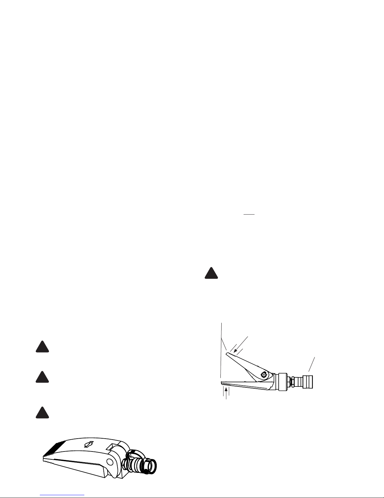
spreader jaws
serrated portion, centrally load
at arrow(s)
3/8”-18NPTF coupler
Always check connections before using. Alteration
!
of these products is strictly prohibited. Use only
those adapters and attachments provided and approved
by the manufacturer.
To reduce the risk of personal injury and/or property
damage, ensure that the rated working pressure of
!
each pressurized attachment be equal to or greater than the
rated working pressure developed by the hydraulic pump.
Figure 1- Typical Spreader Nomenclature
(SR05 shown)
2
Page 3
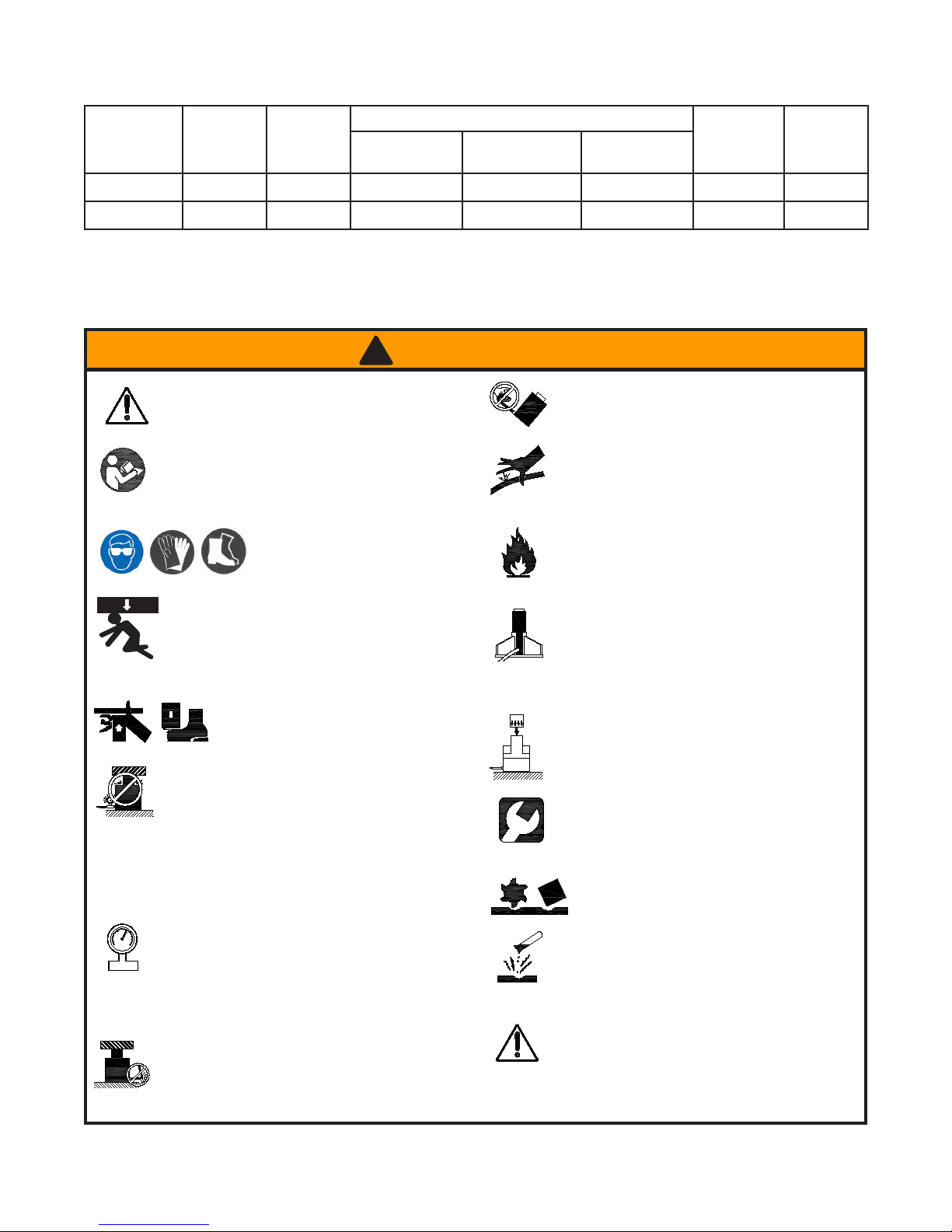
SPECIFICATIONS
Model Pump
Capacity
(psi)
J50040 8,000 4 Ton 11” 15-3/4” 0.998 14 46 lb.
J50100 10,000 10 Ton 13-5/8” 19-3/4” 2.411 13 84 lb.
Ram
Capacity
Closed Height
(in)
Ram Number of
Extended Height
(in)
Effective Area
(in2)
Weight
Attachments
(lb)
! WARNING
may
property damage.
• Study, understand, and follow all instructions
provided with and on this device before use.
with the correct operation, maintenance, and use of rams.
Wear protective gear when
operating hydraulic equipment.
This device is NOT suitable for use as support
device! As the load is lifted, use blocking and
cribbing to guard against a falling load.
clear of a lifted load before it is properly
Never rely on hydraulic pressure to support a load.
during operation.
• Do not exceed rated capacity of the ram or
•
Do not connect a ram to a pump with higher
pressure rating.
• Do not subject ram to a shock loads, a load
dropped suddenly, causing the system pressure to
exceed rated pressure.
The system operating pressure must not exceed
measuring instrument to monitor the operating pressure. Burst
hazard exists if hose, connection or any other component in
the system exceed its rated pressure.
Avoid damaging hydraulic hose. Do not allow
hose to kink, twist, curl, crush, cut or bend so
tightly that uid ow within the hose is blocked or
reduced. Periodically inspect the hose for wear.
Failure to comply with the following warnings
result in personal injury as well as
• The user must be a qualied operator familiar
Stay
supported.
Crush Hazard. Keep hands and feet
away from ram and workpiece
any equipment in the system. The ram is
designed for a max. pressure of 10,000 psi.
the pressure rating of the lowest rated component
the system. Install a pressure gauge or other load
Do not pull, position or move ram setup by
the hose. Use carrying handle or other means
of safe transport.
Do not handle pressurized hoses. Never attempt
to grasp a leaking pressurized hose. Ensure to
release the system pressure before disconnecting
hydraulic hose or connections.
Hydraulic uid can ignite and burn. Keep
heat.
uid leaks. Heat also weakens hose materials.
Ram must be on a stable base which is able
to support the load while pushing or lifting. Use
shims, friction material or constrains to prevent
slippage of the base or load. Ensure ram is fully engaged
into/onto adapters, extension accessories.
Center load on ram. Distribute load evenly
across the entire saddle surface. Do not
off-center loads on a ram. The load can tip
or the ram can “kick out”.
Never try to disassemble a hydraulic ram,
refer repairs to qualied, authorized personal.
Contact BVA Hydraulics tech service for authorized
service center.
Do not subject hose to sharp objects or
heavy impact.
Hose material or seals must not come in
contact with corrosive materials such as
battery acid, creosote-impregnated objects
and wet paint. Never paint a coupler or hose.
• No alteration shall be made to the ram.
• Use only factory authorized fasteners,
accessories and hydraulic uid.
hydraulic equipment away from ames and
Excessive heat will soften seals, resulting in
Heavy
3
Page 4
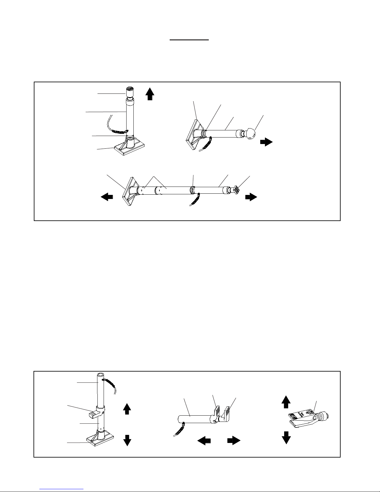
Basic Setup
The capacity of the maintenance kit can be signicantly affected by the number of attachments used and the type of load
applied. The approximate load capacity of each function setup is illustrated below. When two or more extension tubes are used
together, be sure to position the shortest tube further away from the ram.
A. Push & Stretch
Serrated Saddle
Ram
Male Connector
Flat Base
Flat Base
100%
(i) Vertical Push
Extension Tube
Flat Base
Male Connector
(ii) Horizontal Push
Male Connector
(iii) Horizontal Push with Extension
Ram
Ram
Rubber Head
100%
Combination
Head (900)
25%
B. Spread
Ram
25%
Ram Toe
Extension Tube
Flat Base
(i) Vertical Spread
Ram
(ii) Horizontal Spread
Ram Toe
4
Plunger Toe
25%
0.5 Ton
(iii) Hydraulic Spreader
Hydraulic
Spreader
Page 5

OPERATION
ALWAYS monitor pressure, load or position using
!
suitable equipment. Pressure may be monitored by means
of an optional manifold and gauge. Load may be monitored
by means of a load cell and digital indicator.
Note: Any attachment that is not loaded centrally, as through
the centerline of the ram, is considered to be “offset”.
extension tubes and/or offset attachments are used, the
rated capacity is always reduced by 50% for each tube or
offset attachment connected.
1. Pump may be used in horizontal and vertical position as
illustrated on gure 2 below.
Figure 2 - Horizontal and Vertical position
2. Locate and close release valve by turning it clockwise until
rmly closed. (Do not over tighten)
3. Operate by pumping handle. This will send uid from the
pump reservoir into the high pressure hose assembly and
into the ram assembly.
4. Continue pumping until ram reaches desired position.
!
NEVER operate pump with release valve closed and
disconnected from application. If operated in this condition,
the hose and connections become pressurized. This
increases burst hazard. Damage may occur to pump and
its components.
5. To Release Pressure on work piece: Slowly, carefully turn
the release valve counter-clockwise until ram retracts
to desired position. Never turn release valve more than
1/2 full turn. The ram return system is spring loaded and
the release valve system is metered, allowing controlled
retraction of the ram.
When
MAINTENANCE
1. Inspect hoses and connections daily. Replace damaged
com ponen ts i mme di ate ly w ith BVA Hy dra ulics
Replacement Parts only.
2. Tighten connections as needed. Use pipe thread sealing
compound when servicing connections.
3. Use only good quality hydraulic uid. We recommend
Mobil DTE 13M or equivalent. Never use brake uid,
transmission uid, turbine oil, motor oil, alcohol, glycerin
etc. Use of other than good quality hydraulic oil will void
warranty and damage the pump, hose, and application.
Changing Hydraulic Oil
For best performance and increased system life, replace the
complete uid supply at least once per year.
1. With ram fully lowered, remove the oil ller screw from the
pump reservoir as above.
2. Lay the pump on its side and drain the uid into a suitable
container.
Note: Dispose of hydraulic uid in accordance with local
regulations.
3. Set pump in its level upright position.
4. Fill with good quality jack oil to within 3/8" of the oil ller
screw hole opening. Reinstall oil ller screw.
Lubrication
A coating of light lubricating oil to pivot points and hinges
will help to prevent rust and assure that pump assemblies
move freely.
Cleaning
Periodically check the pump piston and ram for signs of rust
or corrosion. Clean as needed and wipe with an oily cloth.
Note: Never use sandpaper or abrasive material on these
surfaces!
Storage
When not in use, store with the pump piston and ram fully
retracted.
How to remove faulty coupler:
If ram does not retract,:
1. Secure load by other means.
2. Depressurize pump and hose
3. Remove the ram from application.
4. Disconnect and replace with new coupler.
Important: Do not attempt to grasp ram with pliers or
wrench without rst wrapping the jaws of such tool with
rags or similar padding.
How to bleed air from system:
1. Place pump at a higher elevation than the hose and ram
as shown in gure 3 below.
2. Operate pump to fully extend and retract the ram 2 or 3
times. The objective is to force the air bubbles up hill and
back to the pump reservoir.
3. To bleed the air from pump reservoir, simply open the oil
ller screw. Re-install after bleeding.
Adding Hydraulic Oil
1. With ram fully lowered, set pump unit in its normal, level
position. Locate and remove oil ller screw.
2. Fill until oil is within 3/8" of the oil ller screw hole opening,
re-install oil ller screw.
Figure 3 - Illustration to bleed air from system
5
Page 6
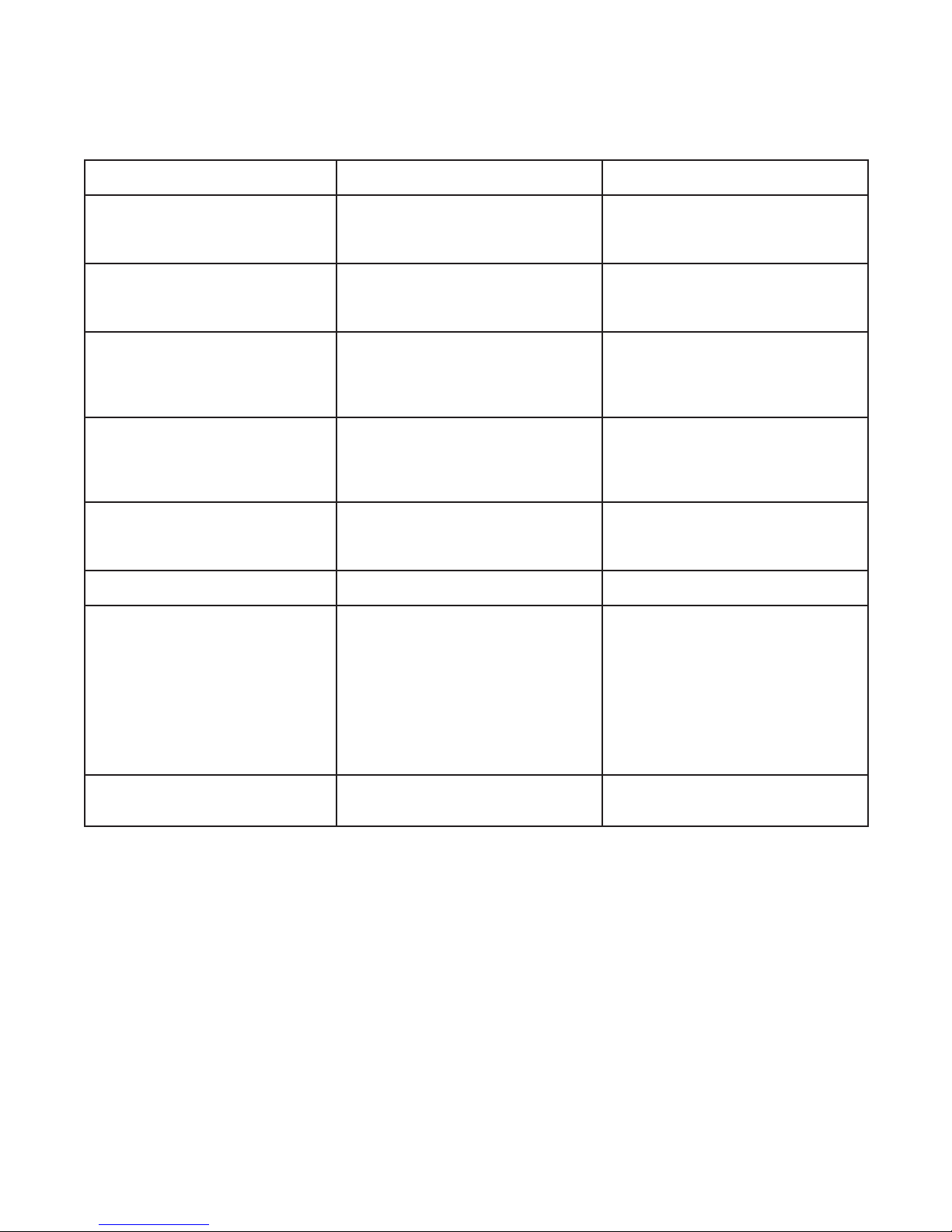
TROUBLESHOOTING GUIDE
The following information is intended as an aid in determining if problem exists. Pump and ram should be repaired only by
authorized BVA Service Center. For repair service, contact service center in your area.
Symptom Possible Causes Corrective Action
Erratic action •
Ramr will not extend, or
respond to pressurized uid
Ram extend only partially • Oil level in pump is low.
Ram move slower than normal • Loose connection or coupler.
Ram responds to pressurized uid, but
system does not maintain pressure
Oil leaking from ram • Worn or damaged seals. • Contact service center.
Ram will not retract or retracts slower
than normal
Air in system or pump cavitation.
• External leakage in ram.
• Ram sticking or binding.
•
Overload condition.
• Loose/Faulty couplers.
• Oil level in pump is low.
•
Overload condition.
• Ram is sticking or binding.
• Pump malfunction.
•
Restricted hydraulic line or tting.
• Pump not working correctly.
• Ram seals leaking.
• Overload condition.
• Pump malfunctioning.
• Ram seals leaking.
• Malfunctioning coupler, damaged
application.
• Pump reservoir overlled.
• Ram damage internally.
• Vent the system (refer to gure 2).
• Contact service center.
• Contact service center.
• Remedy overload condition.
• Tighten/Replace couplers.
• Fill and bleed the system.
• Fill and bleed the system.
• Remedy overload condition.
• Contact service center.
• Contact service center.
• Tighten connection or coupler.
• Clean and replace if damaged.
• Check pump’s operating instructions.
• Contact service center.
• Remedy overload condition.
• Contact service center.
• Contact service center.
• Secure load by other means.
Depressurize pump and hoses,
remove application and replace
coupler.
• Secure load by other means.
Depressurize pump and hoses,
remove application, then drain uid to
proper level.
• Contact service center.
Poor performance • Oil level in pump is low.
• Air trapped in system.
6
• Ensure proper oil level.
• Vent the system (refer to gure 3).
Page 7

LIMITED LIFETIME WARRANTY
BVA Hydraulics®, represented in the United States by SFA Companies [“SFA”] warrants this product to be free from defects in
material and workmanship for the life of the product as long as the original purchaser owns the product. The warranty is nontransferable and is subject to the terms, exclusions, and limitations described below:
• Damaged components, including but not limited to bent rams, dented or crushed ram walls, broken welds or couplers as
well as worn out seals, o-rings and springs are the result of misuse and not covered by warranty and BVA Hydraulics will not
provide any warranty credit for such damaged components.
• This warranty does not cover ordinary wear and tear, overloading, alterations (including repairs or attempted repairs not
performed by BVA Hydraulics or one of its authorized personnel), improper uid use, or use of the product in any manner for
which the product was not intended or the use of which is not in accordance with the instructions or warnings provided with
the product.
• In the unlikely event that a BVA Hydraulics product fails due to material defect in workmanship, you may contact SFA for
disposition. In such cases, the customer’s sole and exclusive remedy for any breach or alleged breach of warranty is limited
to the repair or replacement of the defective product.
• Under no circumstances is BVA Hydraulics liable for any consequential or incidental damage or loss whatsoever.
• THIS WARRANTY IS LIMITED TO NEW PRODUCTS SOLD THROUGH AUTHORIZED DISTRIBUTORS AND OTHER
CHANNELS DESIGNATED BY BVA HYDRAULICS. NO AGENT, EMPLOYEE OR OTHER REPRESENTATIVE OF BVA
HYDRAULICS IS AUTHORIZED TO MODIFY THIS WARRANTY.
• THE FOREGOING IS EXCLUSIVE AND IS IN LIEU OF ALL OTHER EXPRESS AND IMPLIED WARRANTIES, INCLUDING
BUT NOT LIMITED TO THE IMPLIED WARRANTIES OF MERCHANTABILITY AND FOR A FITNESS FOR A PARTICULAR
PURPOSE.
• Components not manufactured by BVA Hydraulics including certain motor systems, gasoline engines, and other are not
covered by this warranty and instead are covered by the manufacturer’s separate manufacturer’s warranty provided in the
package.
• BVA Hydraulics’ liability in all cases is limited to, and will not exceed the purchase price paid for the product.
SFA Companies
10939 N. Pomona Ave. Kansas City, MO 64153
Tel: 888-332-6419
E-mail: [email protected]
7
Page 8
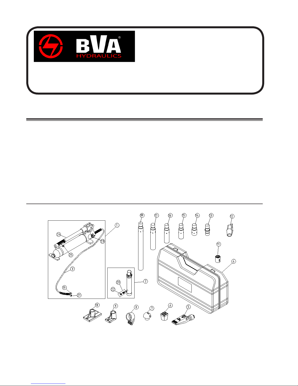
Maintenance Kit
Service Parts
MODEL: J50040
SFA Companies 10939 N. Pomona Ave. Kansas City, MO 64153
Tel: 888-332-6419 * Fax: 816-891-6599
E-mail: [email protected] Website: www.bvahydraulics.com
Note: Not all components of the Maintenance Kit are replacement items, but are illustrated as a
convenient reference of location and position in the assembly sequence.
Parts List
Item Part# Description Qty
01
J0401
Pump Assembly 1
02
J0402
03
J0403
Hose 1
04
J0404
05 J0405 Spreader (1000lb. Cap.) 1
06
J0406
Combination Head (900) 1
07
J0407
Rubber Head 1
08
J0408
Ram Toe (offset) 1
09
J0409
10
J0410
Flat Base 1
11
J0411
Serrated Saddle 1
12
J0412
Wedge Head (offset) 1
13
J0413
Male connector 1
Ram Assembly 1
Case 1
Plunger Toe (offset) 1
Item Part# Description Qty
14
J0414
Extension Tube (3”) 1
15
J0415
16
J0416
Extension Tube (8-1/2”) 1
17
J0417
Extension Tube (16-1/2”) 1
18 J0418 Extension Tube (19-1/2”) 1
19 CRZ14M Hose Coupler (1/4”-18NPTF) 1
20 CRZ14F Ram Coupler (1/4”-18NPTF) 1
21
F040-20012-000
22
F040-30007-000
23
F040-21000-000
24
F040-90009-K03
25
F040-90107-K02
- F0400S-85 Seal Kit -
Extension Tube (6-1/8”) 1
Dust Cover - Hose 1
Dust Cover - Ram 1
Release Valve Knob 1
Pump Handle 1
Oil Filler Screw 1
J50040-M0
rev 12/07
Note: To ensure safe and reliable performance, replace worn or damaged parts with BVA Hydraulics Authorized
Replacement Parts only.
8
Page 9
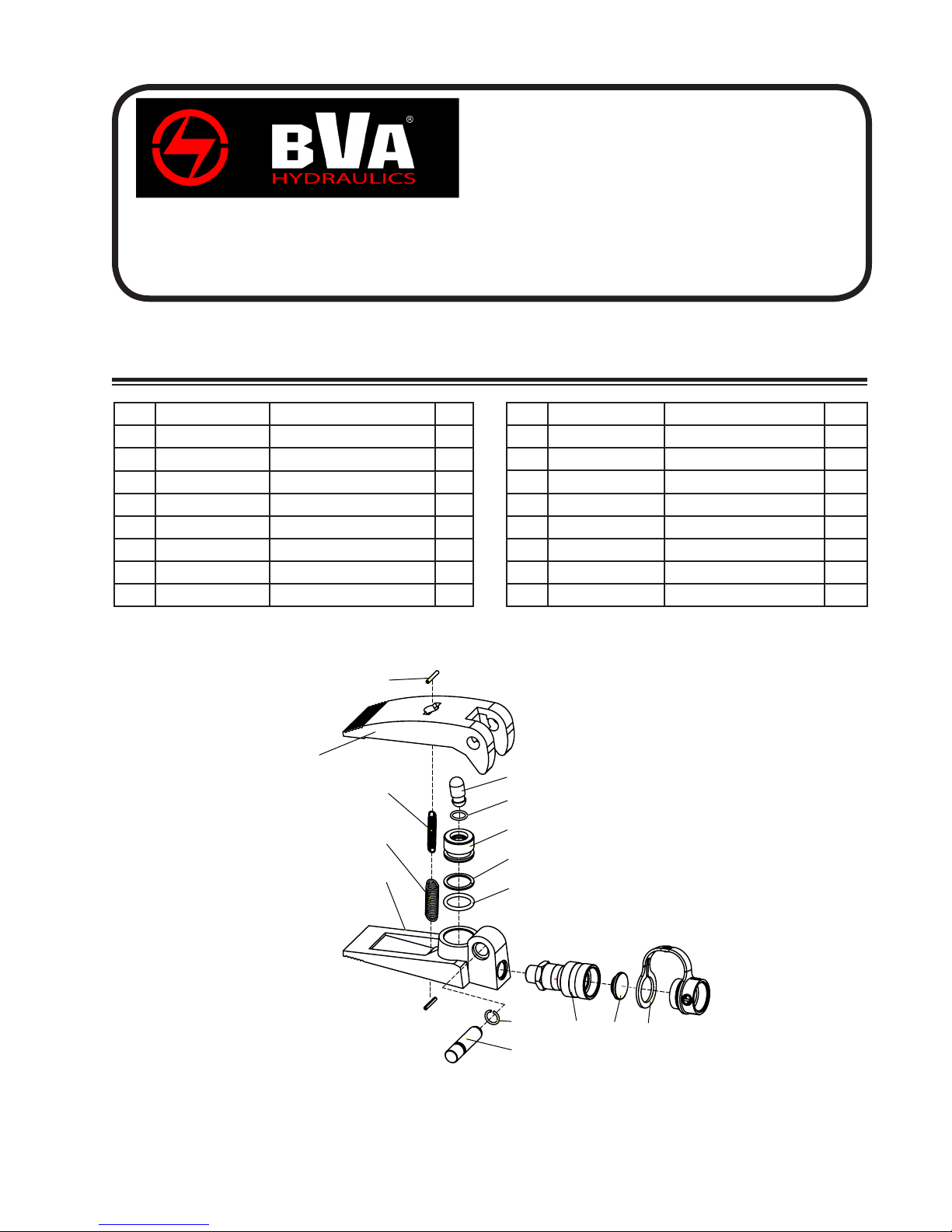
Maintenance Kit
Service Parts
MODEL: SR10
SFA Companies 10939 N. Pomona Ave. Kansas City, MO 64153
Tel: 888-332-6419 * Fax: 816-891-6599
E-mail: [email protected] Website: www.bvahydraulics.com
Note: Not all components of the Hydraulic Spreader are replacement items, but are illustrated as
a convenient reference of location and position in the assembly sequence.
Parts List
Item Part Number Description Qty
1 H51-6-1001-205 Spreader jaw, upper 1
2 601-4-0030-059 Spring pin 2
3 521-2-0060-109 Return spring, inner 1
4 521-2-0090-108 Return spring, outer 1
5 H51-6-1002-207 Spreader base 1
6 H51-6-1003-108 Spreader jaw axle 1
7 H51-6-1004-100 Spring clip 1
8 511-7-0240-406 O-ring 1
2
1
3
Item Part Number Description Qty
9 577-7-0240-103 Back-up ring 1
10 H51-6-1201-203 Ram plunger 1
11 511-7-0138-102 O-ring 1
12 H51-6-1202-104 Ram plunger saddle 1
13 H02-4-6001-104 Coupler, spreader 1
14 H02-6-1008-105 Coupler cap 1
15 H02-4-6003-108 Dust cover 1
16 SR05-M0 OIPM 1
12
11
SR05-M0
ver 07/08
Note: To ensure safe and reliable performance, replace worn or damaged parts with BVA Hydraulics Authorized
Replacement Parts only.
4
5
10
9
8
7
6
9
13
14
15
Page 10
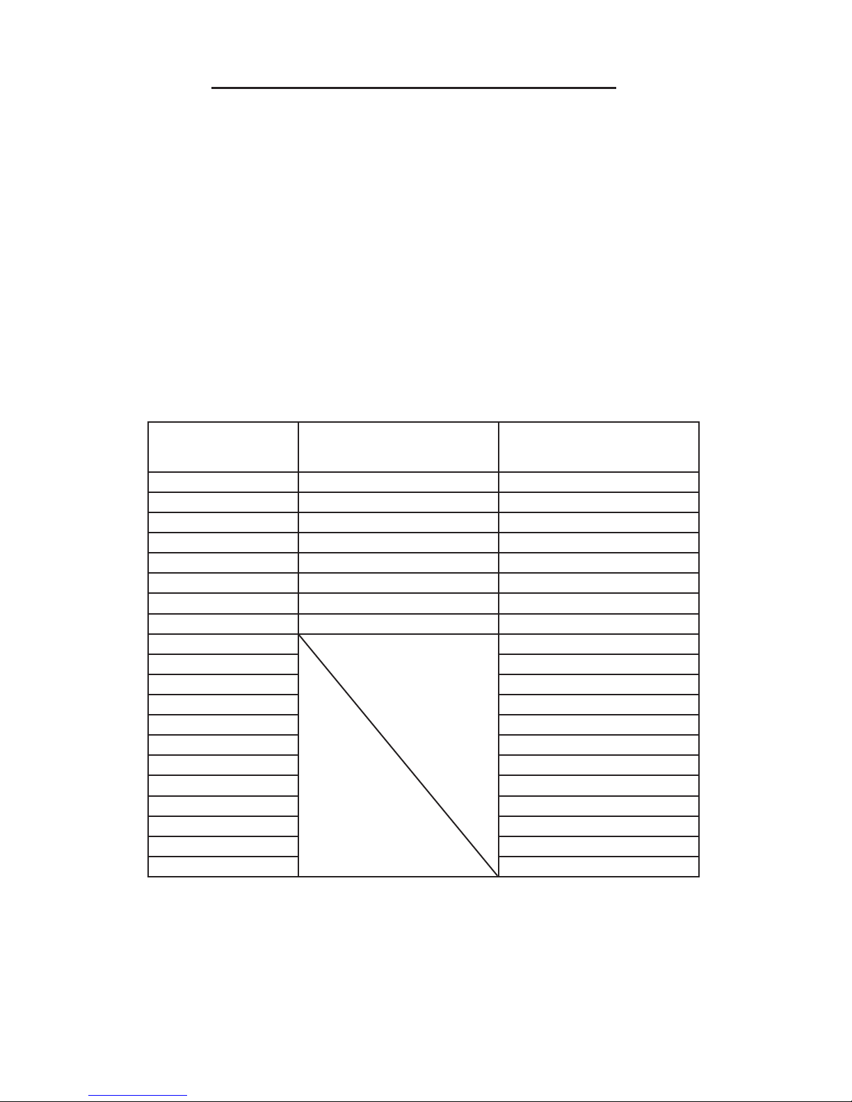
Load - Pressure Correlation For Model J50040 & J50100
Always monitor the force applied to workpiece by using a load cell and indicator or you may monitor pressure developed
in the ram by using an inline pressure gauge, then calculate the applied force using the formula:
F = P x A
For model J50040, A = 0.998 in² ;
For model J50100, A = 2.411 in²
Example1
Model J50040 lifting 5,000 lbs will require what presure?
Pressure = 5,000 lbs / 0.998 in² = 5,010 psi
where F = Force/ Load (lbs);
P = Hydraulic working pressure (psi) and;
A = Ram effective area (in²)
Load
(lbs)
1,000 1,002 415
2,000 2,004 830
3,000 3,006 1,244
4,000 4,008 1,659
5,000 5,010 2,074
6,000 6,012 2,489
7,000 7,014 2,903
8,000 8,016 3,318
9,000 3,733
10,000 4,148
11,000 4,562
12,000 4,977
13,000 5,392
14,000 5,807
15,000 6,221
16,000 6,636
17,000 7,051
18,000 7,466
19,000 7,881
20,000 8,295
Pressure of 4 Ton Ram,
where A = 0.998 in
(psi)
Example2
Model J50100 operating at 6,000 psi will generate
what force?
Force = 6,000 psi x 2.411 in2 = 14,466 lbs
2
Pressure of 10 Ton Ram,
where A = 2.411 in
(psi)
2
10
Page 11

SFA Companies
10939 N. Pomona Ave. Kansas City, MO 64153
Tel: 888-332-6419
E-mail: [email protected]
Page 12

10939 N. Pomona Ave. Kansas City, MO 64153
SFA Companies
Tel: 888-332-6419
E-mail: [email protected]
 Loading...