

Page 1
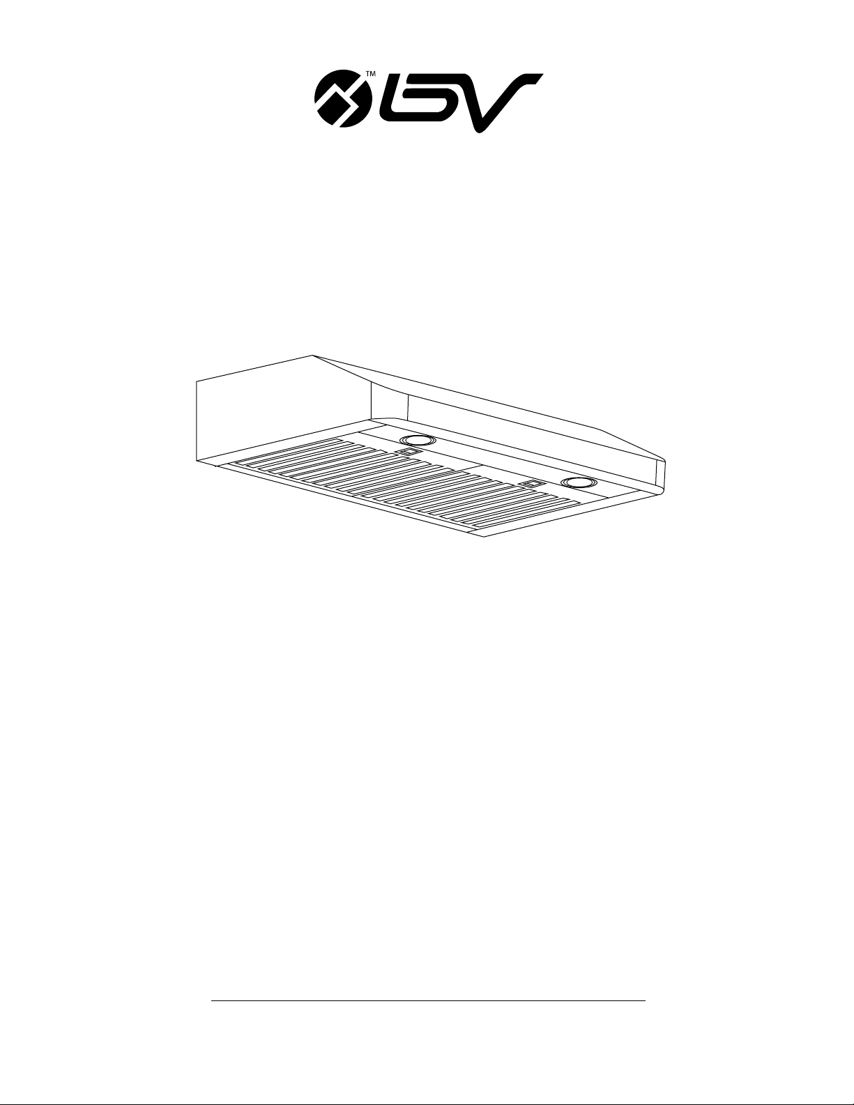
BV-RH-801
Classic Series Under Cabinet Range Hood
USER MANUAL
Page 2

Table of Contents
Important!! Test Before Installation .....................................................................................................................................................
Know Before Installation ......................................................................................................................................................................
Important Safety Notice .......................................................................................................................................................................
Included Parts and Accessories...........................................................................................................................................................
Venting Height Requirements ..............................................................................................................................................................
Venting Methods ..................................................................................................................................................................................
Electrical Requirements and Specications .......................................................................................................................................
Installation Preparation .......................................................................................................................................................................
Installation Instructions .......................................................................................................................................................................
Range Hood Operations ......................................................................................................................................................................
Troubleshooting ...................................................................................................................................................................................
Maintenance and Cleaning .................................................................................................................................................................
Warranty ...............................................................................................................................................................................................
Important!! Test Before Installation.
2
3
4
5
6
8
9
10
11
12
13
14
15
Installer: Leave this guide with the homeowner
Homeowner: Keep this guide for future reference
1. Please unpack the range hood and accessories carefully.
2. Remove the bafe lters, check any dent or damage inside and
outside.
3. If found any loosing parts, please remove them.
4. Place the range hood on a at stable surface, plug in 120V AC
power source. Press the power button and the speed buttons to
turn on.
5. Check if any unusual metal touching noise, check the speed
variation, and press the Light button to check the lights.
6. Verify all functions per Section RANGE HOOD OPERATIONS.
7. Refer to Section TROUBLESHOOTING if any malfunction was
found.
PLEASE READ AND SAVE THESE INSTRUCTIONS
WARNING
TO REDUCE THE RISK OF FIRE, ELECTRIC SHOCK, OR INJURY TO
PERSONS, READ THE FOLLOWING CAREFULLY BEFORE ATTEMPTING
TO ASSEMBLE, INSTALL, OPERATE OR MAINTAIN THE PRODUCT.
Strongly recommend to test the unit before installation for any defective
or damage during shipment.
1. Always disconnect, lock and tag power source before installing or
servicing product. Failure to disconnect power source can result in
re, shock or serious injury.
2. Installation work and electrical wiring must be done by qualied
person(s) in accordance with all applicable codes and standards,
including re-rated construction.
3. When cutting or drilling into wall or ceiling, do not damage electrical
wiring and other hidden utilities.
4. Verify and ensure the rated voltage and frequency (please refer to
the rating label) of the range hood is in compliance with the mains
supply.
BV-RH801 USER MANUAL
2
Page 3
Know Before Installation
Research, plan and prepare the optional accessories and tools.
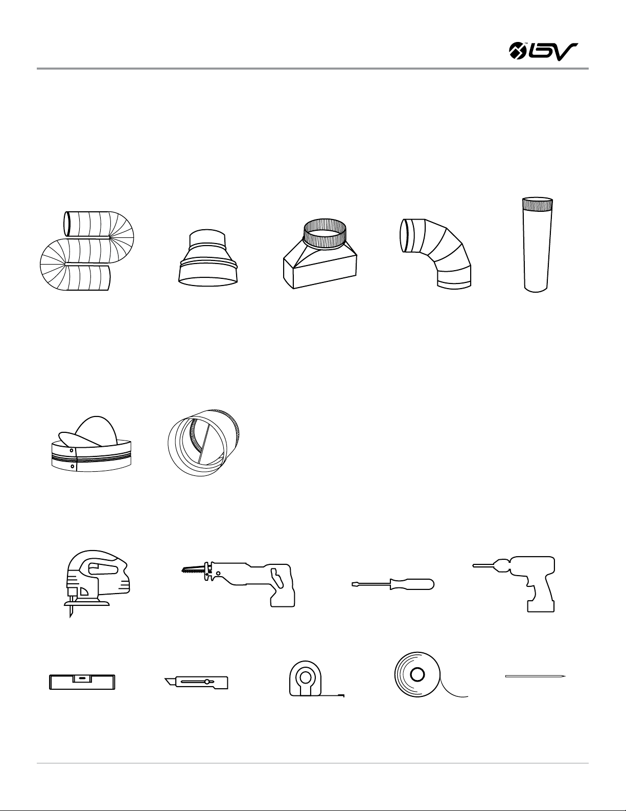
DUCT VENTING AND ACCESSORIES (NOT INCLUDED)
If for new installation or your old range hood doesn’t have exhaust duct, prepare to cut the openings through the bottom of the cabinet, wall,
or top cabinet to ceiling. And purchase the 6” metal duct (or 6” semi-rigid aluminum duct for easy connection). Refer to Section 5 VENTING
METHODS for detail.
Check the existing exhaust duct size. If not 6” round metal duct, try to get the converter / reducer / adapter / elbow as shown in the pictures.
EXHAUST DUCT
DAMPER IS NOT INCLUDED.
Because the damper generates NOISE when the shutters are ipping, we DO NOT recommend installing the damper directly attached to the
top vent of the range hood. You can install the damper between ducts and close to the air outlet near roof or side wall. If the roof cap or side
wall cap already has a damper, don’t need to add the damper.
DAMPER
TOOLS NEEDED FOR INSTALLATION
Cutting tools (jig saw or reciprocating saw), screw drivers or power drill, level, utility knife, measuring tape, duct/foil tape, and pencil.
DAMPER
CONVERTERREDUCER
ELBOW
ADAPTER
JIG SAW
LEVEL
2 PEOPLE ARE REQUIRED FOR INSTALLATION
BV-RH801 USER MANUAL
SCREW DRIVERSRECIPROCATING SAW
MEASURING TAPEUTILITY KNIFE
DUCT/FOIL TAPE
POWER DRILL
PENCIL
3
Page 4

Important Safety Notice
READ ALL INSTRUCTIONS BEFORE INSTALLING AND OPERATING THIS APPLIANCE
INSTALLATION CAUTIONS
1. The installation in this manual is intended for qualied installers,
service technicians or persons with similar qualied background.
Installation and electrical wiring must be done by qualied professionals and in accordance with all applicable codes and standards,
including re-rated construction.
2. DO NOT attempt to install this appliance yourself. Injury could result
from installing the unit due to lack of appropriate electrical and
technical background.
TO REDUCE THE RISK OF FIRE, ELECTRIC SHOCK, OR INJURY TO PERSONS:
1. For general ventilating use only. DO NOT use to exhaust hazardous
or explosive materials and vapors.
2. The combustion air ow needed for safe operation of fuel-burning
equipment may be affected by this unit’s operation. Follow the
heating equipment manufacturer’s guideline and safety standards
such as those published by the National Fire Protection Association
(NFPA), and the American Society of Heating, Refrigeration and Air
Conditioning Engineers (ASHRAE), and the local code authorities.
3. Before servicing or cleaning unit, unplug the power cord or switch
power OFF at service panel and lock service panel to pre-vent power from being switched ON accidentally.
4. Clean grease laden surfaces frequently. To reduce the risk of re
and to disperse air properly, make sure to vent air outdoors. DO
NOT vent exhaust into spaces between walls, crawl spaces, ceiling,
attics or garages.
3. Range hood may have very sharp edges; please wear protective
gloves if it is necessary to remove any parts for installing, cleaning
or servicing.
4. Before installation, turn on the range hood to test for any damage /
defect due to shipping.
5. Due to the size and weight of this range hood, two people installation is required.
6. Sufcient air is needed for proper combustion and exhausting of
gases through the duct to prevent back drafting.
7. When cutting or drilling into wall or ceiling, be careful not to damage electrical wiring or other hidden utilities.
8. All electrical wiring must be properly installed, insulated and
grounded.
9. Old duct work should be cleaned or replaced if necessary to avoid
the possibility of a grease re.
10. Check all joints on duct work to insure proper connection and all
joints should be properly taped.
11. Use this unit only in the manner intended by the manufacturer. If
you have questions, contact the vendor
5. Use only metal ductwork and this unit MUST be grounded.
TO REDUCE THE RISK OF A STOVE TOP GREASE FIRE:
1. Keep all fan, bafe, spaces, lter, and grease-laden surfaces clean.
Grease should not be allowed to accumulate on fan, bafe, spaces,
and lter.
2. Always turn range hood ON when cooking at high heat or when
cooking aming foods.
3. Use high settings on cooking range only when necessary.
TO REDUCE THE INJURY IN THE EVENT OF A GAS LEAKS:
1. Extinguish any open ame.
2. DO NOT turn on the lights or any type of appliance.
3. Open all doors and windows to disperse the gas. If you still smell
gas, call the gas company and re department, or 911 immediately.
BV-RH801 USER MANUAL
4. Never leave surface units (countertop/stove) unattended at high
settings. Boil overs cause smoking and greasy spillover that may
ignite. Heat oils slowly on low or medium settings.
5. Clean ventilating fan frequently.
6. Always use cookware appropriate for the size of the surface element.
4
Page 5
Important Safety Notice
TO REDUCE THE RISK OF INJURY IN THE EVENT OF A STOVE TOP GREASE FIRE:
1. SMOTHER FLAMES with a close-tting lid, cookie sheet, or metal
tray, then turn OFF the burner. BECAREFUL TO PREVENT BURNS.
NEVER PICK UP A FLAMING PAN—you may be burned. KEEP FLAMMABLE OR COMBUSTIBLE MATERIAL AWAY FROM FLAMES. If the
ames DO NOT go out immediately, EVACUATE AND CALL THE FIRE
DEPARTMENT or 911.
2. DO NOT USE WATER, including wet dishcloths or towels — a violent
steam explosion will result.
Your safety and the safety of others are very important. We have provided many important safety messages in this manual and on your
appliance. Always read and obey all safety messages. All safety messages will tell you what the potential hazard is, tell you how to reduce the
chance of injury, and tell you what can happen if the instructions are not followed.
This is the safety alert symbol. This symbol alerts you to potential hazards that can hurt you and others. All
WARNING
safety messages will follow the safety alert symbol and the word “WARNING”.
3. Use an extinguisher ONLY if:
a. You know you have a Class A, B, C extinguisher, and you already
know how to operate it.
b. The re is small and contained in the area where it is started.
c. The re department is being called.
d. You can ght the re with your back to an exit.
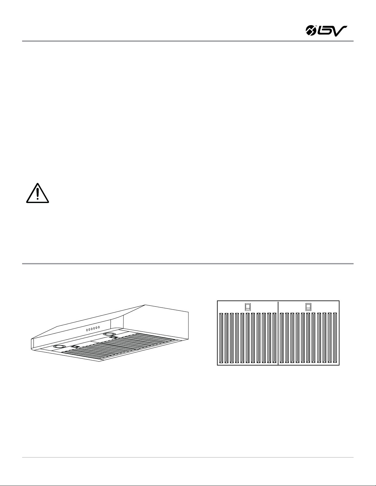
Included Parts and Accessories
RANGE HOOD BAFFLE FILTERS
Note: the supplied are subjected to change without notice due to product development.
BV-RH801 USER MANUAL
5
Page 6
Venting Height Requirements
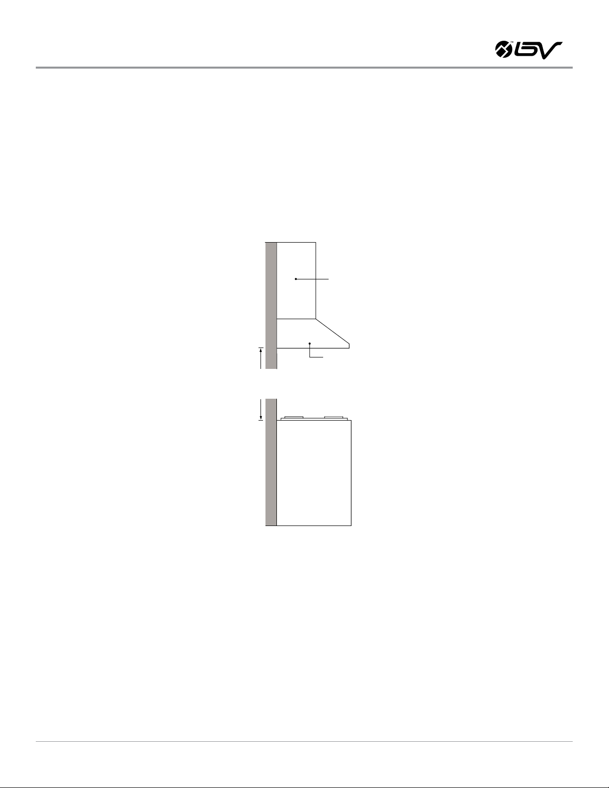
VENTING HEIGHT REQUIREMENTS
1. Vent system must terminate to the outside (roof or side wall).
2. DO NOT terminate the vent system in an attic or other enclosed
area.
3. DO NOT use 4” (10.2 cm) laundry-type wall caps.
4. Use metal/aluminum vent only. Rigid or exible metal / aluminum
vent duct is recommended.
5. DO NOT use plastic vent.
Min 24” Max 32”
Recommended 27” to 30”
6. Always keep the duct clean to ensure proper airow.
7. Measure and estimate the following gures before installation:
a. Distance between the countertop/stove to the bottom of the range
hood. Recommend 27” to 30” for ideal performance, minimum 24”
(inches) for safety concern.
b. Height of hood and duct.
Cabinets
Range Hood
FOR THE MOST EFFICIENT & QUIET OPERATION:
1. A distance of 27” to 30” is recommended between stove top and
the bottom of range hood.
2. The vent duct isn’t included. It is recommended that the range hood
be vented vertically through the roof through 6” (15.24 cm) or bigger round metal/aluminum vent work, such as 6 in. x 8 ft. semi-rigid
aluminum exible duct.
3. The size of the vent should be uniform.
4. Use no more than three 90° elbows.
5. Make sure there is a minimum of 24” (61 cm) of straight vent be-
tween the elbows if more than one elbow is used.
Stove Top
6. DO NOT install two elbows together.
7. The length of vent system and number of elbows should be kept to
a minimum to pro-vide efcient performance.
8. The vent system should have a damper. The damper can be installed in the duct near to the roof or wall cap. Not recommend to
use damper on top of the range hood, because the damper has big
noise.
9. Use silver tape or duct tape to seal all joints in the vent system.
10. Use caulking silicone to seal exterior wall or roof opening around
the cap.
BV-RH801 USER MANUAL
6
Page 7
Venting Height Requirements
IMPORTANT:
1. Please use Duct Run Calculation below to compute total available
duct run when using elbows, transitions and caps.
2. ALWAYS, when possible, reduce the number or transitions and
turns. If long duct run is required, increase duct size from 6” to
7”, 8” or 9”. If a reducer is used, install a long reducer instead
of a pancake reducer. Reducing duct size will restrict airow and
decrease airow, thus reduce duct size as far away from opening as
possible.
3. If turns or transitions are required: Install as far away from opening
and as far apart, between 2, as possible.
4. Minimum mount height between stove top to hood bottom should
be no less than 24-inch.
MINIMUM DUCT SIZE:
1. Round - 6” minimum
2. Rectangular - 3-1/4 x 10” minimum (requires a 6” to 3-1/4x10” adaptor, not supplied)
CALCULATION VENT SYSTEM LENGTH
To calculate the length of the system you need, deduct the equivalent feet for each vent piece used in the system from the recommended maximum duct run.
5. Maximum mount height between stove top to hood bottom should
be no higher than 32-inch.
6. It is important to install the hood at the proper mounting height.
Hoods mounted too low could result in heat damage and re
hazard; while hoods mounted too high will be hard to reach and will
reduce its performance and efciency.
7. If available, also refer to stove top manufacturer’s height clearance
requirements and recommended hood mounting height above
range.
DUCT RUN CALCULATION
6” or 3-1/4 x 10” duct
Each 90° elbow used
Each 45° elbow used
Each 6” to 3/12 x 10” transition used
Side wall cap with damper
Each 90° elbow used
RECOMMENDED MAxIMUM STRAIGHT DUCT RUN
50 ft
VENT PIECE DEDUCTION
9 ft
5 ft
7 ft
0 ft
0 ft
DUCT RUN CALCULATION ExAMPLE:
One roof cap, two 90º elbow, and one 45º elbow used:
0ft + 9ft + 9ft + 5ft = 23ft used.
Deduct 23ft from 50ft, 27ft maximum available for the duct run.
BV-RH801 USER MANUAL
7
Page 8
Venting Methods
VENTING METHODS
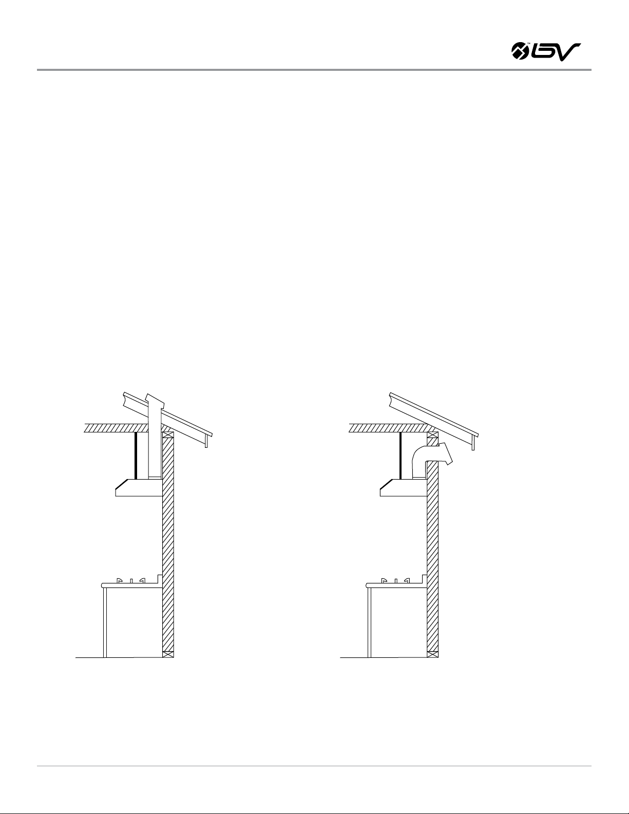
1. This range hood is 6” top venting through the roof or wall.
2. Vent work can terminate either through the roof or wall as shown
below.
3. A minimum of 6” round duct (purchase separately) or 3-1/4 x 10”
rectangular duct (purchase separately) must be used to maintain
maximum airow efciency.
IMPORTANT:
1. NEVER exhaust air or terminate duct work into spaces between
walls, crawl spaces, ceiling, attics or garages. All exhaust must be
ducted to the outside.
2. Fasten all connections with sheet metal screws and tape all joints
with certied Silver Tape or Duct Tape.
3. Use caulking to seal exterior wall or roof opening around the cap.
Roof Cap
4. Always use rigid or semi-rigid type metal/aluminum ducts if available to maximize airow.
5. Decide the location of the venting pipe from the hood to the outside.
6. A straight, short vent run will allow the hood to perform more
efciently. Try to avoid as many transitions, elbows, and long run as
possible. This may reduce the performance of the hood.
Cabinet
Range Hood
Stove Top
TOP VENTING ROOF ExHAUST TOP VENTING WALL ExHAUST
Side Wall Cap
BV-RH801 USER MANUAL
8
Page 9
Electrical Requirements and Specications
IMPORTANT: OBSERVE ALL GOVERNING CODES AND ORDINANCES.
1. It is the customer’s responsibility to contact a qualied electrical
installer.
2. A 120 Volt, 60 Hz, AC only, fused electrical supply is required on a
15-amp circuit.
3. DO NOT have a fuse in the neutral or ground circuit.
4. The 3-prong outlet should be grounded. If the power cord plug is not
used, the power cord’s green wire should be connected to ground.
Check with a qualied electrician if you are not sure that the range
hood is properly grounded.
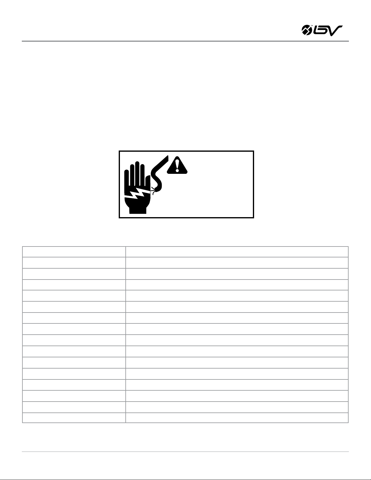
Hazard of electrical shock!
Do not perform service on electrically live system.
Disconnect the main electrical supply before
servicing this device. Touching electrical connectors
or other exposed electrical circuitry inside this range
hodd when they are energized could result in death,
serious bodily injury, or propety damage
SPECIFICATIONS
5. DO NOT ground to a gas pipe.
6. The range hood must be connected with copper wire/plug only.
7. The range hood should be connected directly to the fused disconnect (or circuit breaker) box through exible armored or non-metallic sheathed copper cable. ETL listed strain relief must be provided
at each end of the power supply cable.
WARNING
Body Design
Power Rating
General Input Power
Motor Input Power
Ampere
Levels Of Speed Control
Airow (Q/L/M/H)
Noise Level (Q/L/M/H)
Number Of Motors
Motor Type
Fan Type
Control Type
Filtration Type
Illumination
Venting Size
Interference Protection
Seamless Stainless Steel, Satin Finish
120V / 60Hz (USA & Canada standard)
156W (150W + 2x3W)
Max: 150W (75W + 75W), Min: 110W (55W + 55W)
2 A
4 Levels
385CFM / 490CFM / 615CFM / 900CFM
1.5Sone(46dB) / 3.5Sone(58dB) / 5.3Sone(64dB) / 7.5Sone(69dB)
2 Motors
Single Chamber Ultra Quiet
Centrifugal Blower
Soft Touch Electronic Control Panel with LED Light
Stainless Steel Bafe Filter
3W 12V Maximum
Top, 6 inches Round
Radio Frequency Interference Protected
BV-RH801 USER MANUAL
9
Page 10

Installation Preparation
STEPS TO FOLLOW
1. Please unpack the range hood and accessories carefully.
2. Remove the bafe lters.
3. Check for any dent or damage inside and outside. If found any
loosing parts, please remove them.
4. Place the range hood on a at stable surface. Connect the range
hood to a designated standard outlet (120-Volt, 60Hz, AC only).
Press the power button and the speed buttons to turn on.
5. Check if any unusual metal touching noise, check the speed
variation, and press the Light button to check the lights. Verify all
functions by referring to Section RANGE HOOD OPERATIONS. Refer
to Section TROUBLESHOOTING if any malfunction was found.
6. Place all supplied parts and required hardware on a at stable surface and verify the existence of all supplied parts listed on Section
INCLUDED PARTS AND ACCESSORIES.
7. Carefully remove the white plastic protective lm from the range
hood if any. The white protective lm might not cover all stainless
steel area; it was removed prior for welding or packing.
NOTE: To avoid damage to your hood, prevent debris from entering the vent opening.
CAUTION: If moving the cooking range is necessary to install the hood, unplug the power on an electric range. SHUT OFF THE GAS VALVE
BEFORE MOVING A GAS RANGE.
BV-RH801 USER MANUAL
10
Page 11
Installation Instructions
1. Installation planning
a. Measure the distance between stove top and the bottom of
range hood. A distance of 27” to 30” is recommended.
b. Minimum 24” is required for safety concern.
c. Decide the venting method and the location of the venting
pipe from the hood to the outside.
d. Purchase any necessary accessories from a hardware store,
such as duct, elbow, reducer, damper, duct tape, screws, etc.
e. Find and mark the stud locations using a stud nder to plan
the mounting locations rmly.
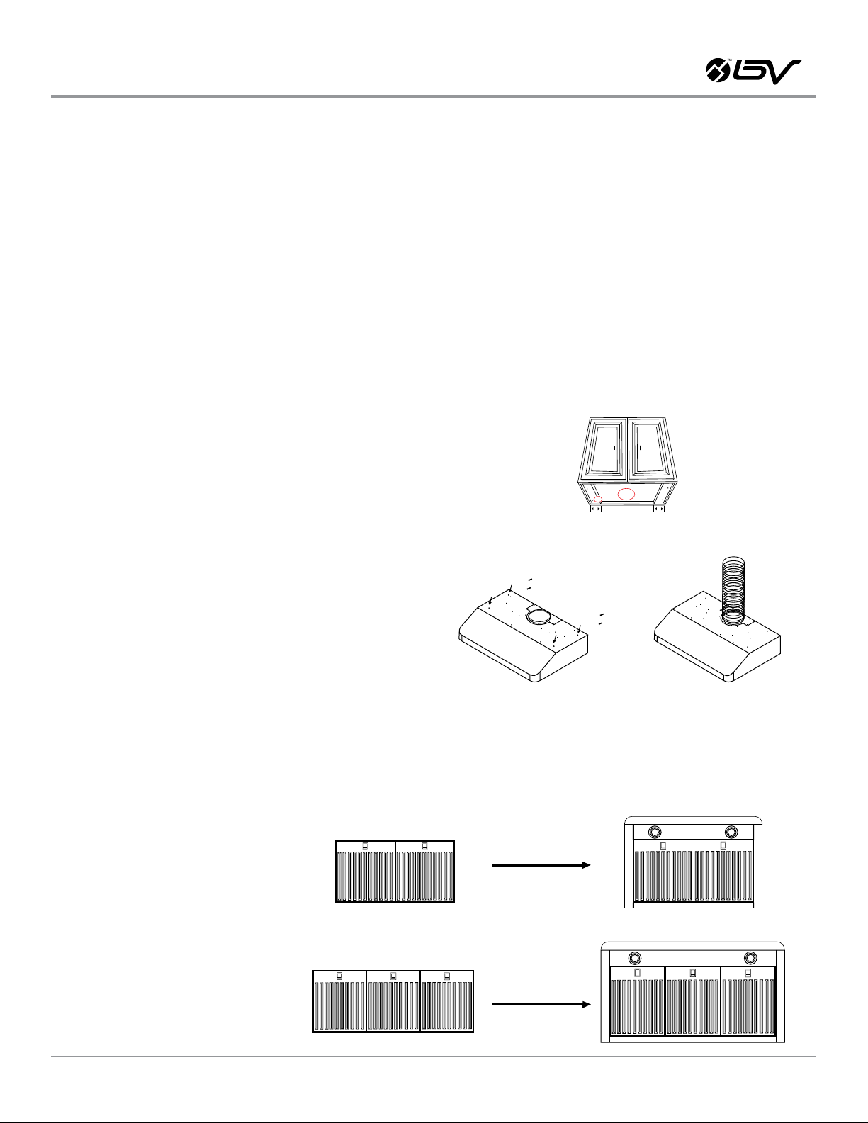
2. Measure the top vent and the power cord positions, cut the
openings (slightly larger for easy accessible) for hood exhaust and
power cord under the cabinet.
3. For installing under the cabinet with recessed bottom, attach
4-inch wide wood ller strips (not provided) on each side.
4. Puncture the power cord’s knockout hole and through the power
cord from inside of the range hood to outside.
5. Puncture the knockout screw holes on the top for screw mounting
under the cabinet.
6. Mount this range hood under the cabinet, 2 people are required
for this installation.
7. Use 6” round metal duct (or semi-rigid aluminum duct, follow
building codes in your area) to connect the exhaust on the hood
to the duct-work above. Use foil tape or duct tape to make all
joints secure and air tight.
8. Connect the range hood to a designated grounded standard outlet.
a Or cut off the plug and connect three wires (black, white and
green) to house wires and cap with wire connectors. Connect
according to colors (i.e. black to black, white to white, and
green to green). Store excess wires in the wiring box.
9. Install bafe lters and stainless spacer if any.
10. Turn power ON in control panel. Check all lights and fan operations.
4”WIDE 4”WIDE
a. Draw power cord through cabinet access opening and center
the hood beneath the cabinet.
b. From inside of the hood, place screws into the exact center
of each knockout hole and secure to cabinet bottom. Finish
tightening all screws until secure.
c. CAUTION: Make sure the range hood is secure before
releasing!
d. For safety purpose, mount the screws through the pre-drilled
mounting holes or/and drill new holes from inside the back of
the hood to the studs or lumbers. For a more secure installation, use as many mounting holes as needed to secure from
the inside of hood.
BAFFLE FILTERS AND STAINLESS STEEL SPACERS
30” Range Hood
WALL
36” Range Hood
BV-RH801 USER MANUAL
11
Page 12
Range Hood Operations
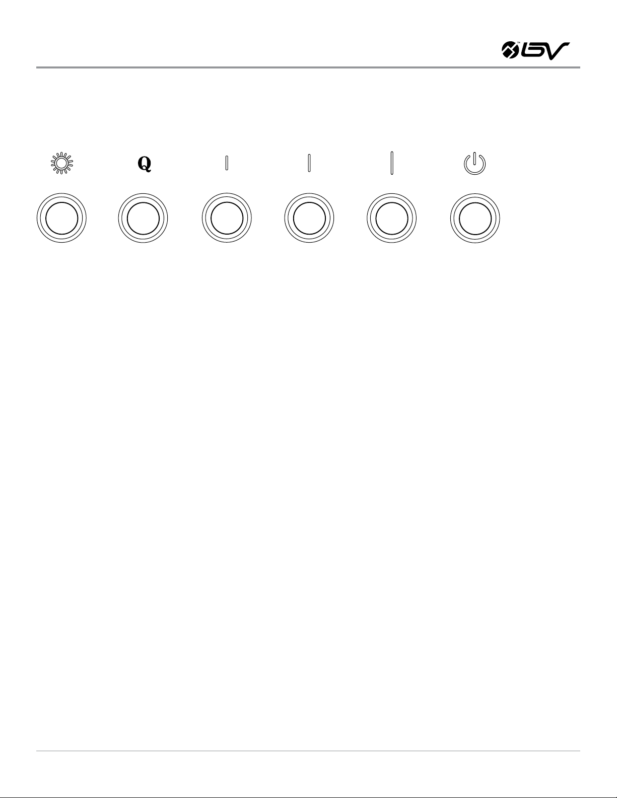
CONTROL PANEL LAYOUT AND BUTTONS CONFIGURATIONS:
LIGHT CONTROL:
a. Press Light Control button once to turn on the lights, and once
again to turn off the lights.
b. The Light Control button operates independently from the Power
Control (On/Off) button. Pressing the
c. Power Control button will not turn LED lights ON or OFF.
d. Please turn off the LED lights before activating the power-off delay
function. While Light Control button will NOT be affected by the
power-off delay function.
TURNING FAN ON:
a. Always turn fans ON couple minutes before cooking to establish
air ow and allow fans to run for a few minutes after cooking for
cleaner air in the kitchen.
The Power Control (On/Off) button must be pressed before a Speed
Control button can be activated.
BLOWER SPEED SELECTION:
a. With the range hood is OFF, press the Power Control (On/Off) but-
ton once. The LED on the Power Control button will be illuminated.
b. While the Power Control LED is illuminated, press one of the four
speed control button (Quiet, Low, Medium, and High) to activate
the desired speed (the LED on the speed control button will turn
on).
POWER-OFF DELAY FUNCTION:
a. When the fans are operating in any speed, press the Power
Control (On/Off) once to turn on the 3-minute power-off delay
function.
b. While the fans are in 3-minute power-off delay mode, press the
Power Control (On/Off) button once to turn OFF the fans immediately.
POWER CONTROL (ON/OFF):
a. When the fans are operating in any speed, press the Power Con-
trol (On/Off) button twice to turn OFF the fans immediately.
OPERATION CAUTIONS:
a. Read and understand all instructions and warnings in this manual
before operating the appliance.
b. Always leave safety grills and lters in place. Without these
components, operating blowers could catch on to hair, ngers and
loose clothing.
c. NEVER dispose cigarette ashes, ignitable substances, or any
foreign objects into blowers.
d. NEVER leave cooking unattended. When frying, oil in the pan
can easily overheat and catch re. The risk of self-combustion is
higher when the oil has been used several times.
e. NEVER cook on “open” ames under the range hood. Check
deep-fryers during use: Superheated oil may be ammable.
c. To change the fan speed, press another speed control button. The
LED on the speed control button will become illuminated accordingly.
BV-RH801 USER MANUAL
12
Page 13
Troubleshooting
If the range hood or LED light does
not operate after installation
WARNING
Hazard of electrical shock!
Do not perform service on electrically live system.
Disconnect the main electrical supply before
servicing this device. Touching electrical connectors
or other exposed electrical circuitry inside this range
hodd when they are energized could result in death,
serious bodily injury, or propety damage
1. Check if the range hood has been plugged in, make sure that all power has been
turned back ON, fused not blown and all electrical wiring are properly connected.
2. Swap out light assembly to working ones to deter-mine whether it is caused by
defective bulbs. See Replacing the Light Bulbs on Page 14.
The range hood vibrates when the
blower is on
The blower or fan seems weak
The lights work but the blower is
not spinning at all, is stuck or is rattling.
The hood is not venting out properly.
1. The range hood might not have been secured properly on to the cabinet or wall.
1. Check that the duct sized used is at least 6” or 3-1/4 x 10”. Range hood WILL
NOT function efciently with insufcient duct size. For example: 7” duct over 6”
top vent and loosely secured.
2. Check if duct is clogged or if damper unit (half-circular apper) is not installed
correctly or opening properly. A tight mesh on a side wall cap unit might also
cause restriction to the air ow.
1. The blower might be jammed or scraping the bottom due to shipping damage.
2. Disconnect the power cord, remove the fan grill and the fan blade, might see the
fan blade or/and motor is not in the proper position (offset from the center). Try
to x/adjust it or please contact us immediately.
1. Make sure the distance between the stove top and the bottom of the hood is
within recommended 27” and 30” in distance. *Due to different ceiling height
congurations, recommended height may not be applicable.
2. Reduce the number of elbows and length of duct work. Check if all joints are
properly connected, sealed, and taped.
BV-RH801 USER MANUAL
3. Make sure the power is on high speed for heavy cooking.
13
Page 14
Maintenance and Cleaning
CLEANING:
1. The saturation of greasy residue in the blower and lters may
cause increased inammability. Keep unit clean and free of
grease and residue build-up at all times to prevent possible res.
2. For optimal operation, clean range hood and all bafe/spacer/
lter regularly. Regular care will help preserve the appearance of
the range hood.
3. Filters must be cleaned periodically and free from accumulation of
cooking residue. Old and worn lters must be replaced immediately.
4. DO NOT operate blowers when lters are removed. Never disassemble parts to clean without proper instructions.
5. Disassembly is recommended to be performed by qualied personnel only. Read and understand all instructions and warnings
in this manual before proceeding.
SAFETY WARNING: Never put your hand into area housing the fan
while the fan is operating!
CLEANING ExTERIOR STAINLESS STEEL SURFACES:
1. Clean periodically with hot soapy water and clean cotton cloth.
DO NOT use corrosive or abrasive detergent, or steel wool/scoring
pads, which will scratch and damage the stainless steel surface.
For heavier soil use liquid degrease cleaner.
2. If hood looks splotchy, use a stainless steel cleaner to clean the
surface of the hood. Avoid getting cleaning solution onto or into
the control panel. Follow directions of the stainless steel cleaner.
3. CAUTION: DO NOT leave on too long as this may cause damage
to hood nish. Use soft towel to wipe off thecleaning solution,
gently rub off any stubborn spots. Use dry soft towel to dry the
hood.
4. After cleaning, you may use nonabrasive stainless steel polish, to
polish and buff out the stainless luster and grain.
5. Always scrub lightly, with clean cotton cloth, and with the grain.
6. DO NOT allow deposits to accumulate or remain on the hood.
7. DO NOT use ordinary steel wool or steel brushes. Small bits of
steel may adhere to the surface and cause rusting.
8. DO NOT allow salt solutions, disinfectants, bleaches, or cleaning
compounds to remain in contact with stainless steel for extended
periods. Many of these compounds contain chemicals, which may
be harmful. Rinse with water after exposure and wipe dry with a
clean cloth.
CLEANING STAINLESS STEEL BAFFLE FILTERS:
1. Remove all bafes, spacers, lters, discard oil and residue.
2. IMPORTANT: Drain oil from bafes, spacers, and lters before oil
and residue overow!
3. Wash with warm soapy water. NOTE: Stainless steel bafes and
spacers are top rack dishwasher safe.
4. Dry thoroughly before replacing and follow directions for installation in reverse.
5. Filters should be cleaned after every 30 hours of use.
REPLACING FILTERS:
1. Should lters wear out due to age and prolonged use, replace the
bafe lters immediately.
REPLACING THE LIGHT BULBS:
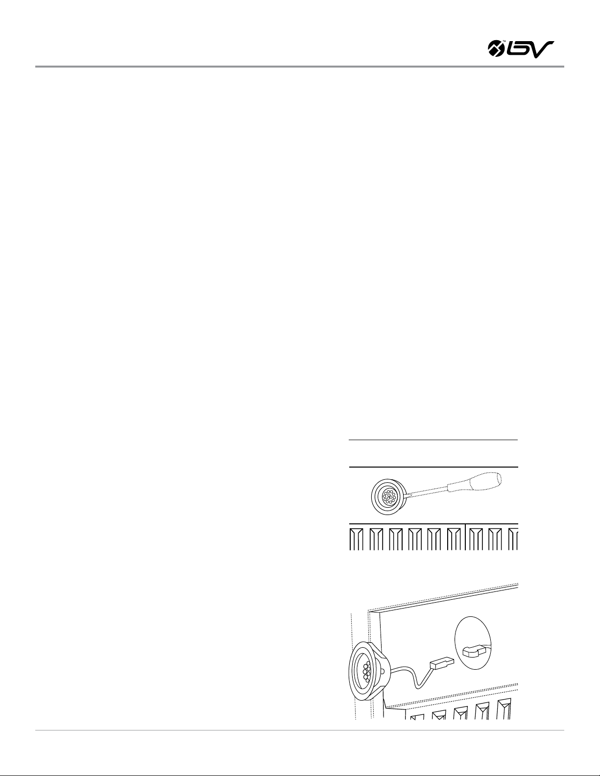
This range hood uses LED bulbs: 3W 12V.
Make sure the range hood is unplugged or turn OFF breaker.
1. Gently pull the defective bulb assembly straight out from the
edge, and then disconnect the wires.
2. Connect the new LED bulb’s wires and snap the new LED assembly into the housing hole.
3. Turn ON breaker/power and to test the range hood for operation.
BV-RH801 USER MANUAL
14
Page 15

Warranty
Please provide an original dated proof of purchase (sales receipt /
invoice) in order to obtain warranty.
ONE YEAR PARTS WARRANTY:
1. For one year from the date of original purchase, we will provide
free of charge, non-consumable replacement parts or components that failed due to manufacturing defects. Subject to the
conditions and limitations set forth below, we will, at its option, either repair or replace any part of its products that prove defective
by reason of improper workmanship or materials.
2. Repaired parts or replacement products will be provided by us
on an exchange basis, and will be either new or refurbished to be
functionally equivalent to new.
3. The consumer is responsible for all shipping costs.
4. Consumable parts not covered by this warranty include but not
limited to: light bulbs, stainless steel bafe lters.
WHO IS COVERED?
1. This warranty is extended to the original purchaser for products
purchased for ordinary home use in the continental USA.
THIS WARRANTY WILL BE VOIDED WHEN:
1. Product damaged through negligence, improper installation,
accident, abuse, misuse, natural disaster, insufcient or excessive electrical supply, abnormal mechanical or environmental
conditions, or any unauthorized repair, disassembly, modication,
or failure to follow installation instructions.
WHAT IS NOT COVERED?
1. Consumable parts such as light bulbs, stainless steel bafe
lters. The natural wear of nish, and wear due to improper maintenance, use of corrosive and abrasive cleaning products, pads,
and oven cleaner products.
2. Chips, dents or cracks due to abuse, misuse, freight damage, or
improper installation.
3. Damage of product caused by accident, re, oods or act of God.
It is not liable for, and does not cover under warranty, any loss of
properties or any costs associated with removing, servicing, installing, or determining the source of problems with our products.
2. When product is used commercially or other than its intended
purpose.
3. Damaged because of improper connection with equipment of
other manufacturers. Repaired or modied by anyone other than
our authorized agents.
4. This limited warranty also does not apply to any product on which
the original identication information has been altered, obliterated or removed, has not been handled or packaged correctly, has
been sold as second-hand.
This warranty is valid in the United States. It is non-transferable and applies only to the original purchaser and does not extend to subsequent
owners of this product. Any applicable implied warranties, including the warranty of merchantability, are limited in duration to a period of
express warranty as provided herein beginning with the date of original purchase at retail and, no warranties, whether express or implied, shall
apply to this product thereafter.
To obtain warranty service, you may contact us, its dealer or distributor from which you purchased the product. Please conrm the terms of your
dealer’s or distributor’s policies prior to contacting. Typically, you must include product identication information, including model number and
lot number with a detailed description of the problem you are experiencing. You must also include proof of the date of original retail purchase
as evidence that the product is within the applicable warranty period.
BV-RH801 USER MANUAL
15
 Loading...